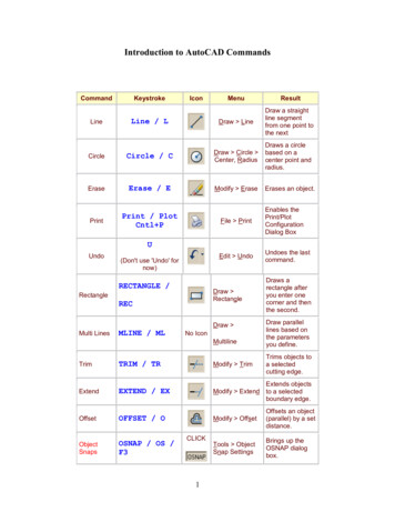
Transcription
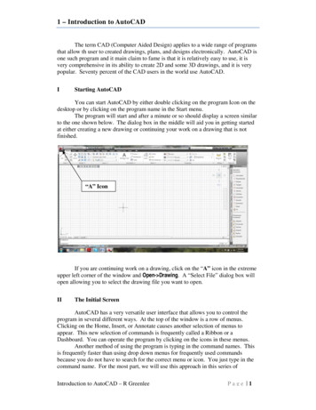
1 – Introduction to AutoCADThe term CAD (Computer Aided Design) applies to a wide range of programsthat allow th user to created drawings, plans, and designs electronically. AutoCAD isone such program and it main claim to fame is that it is relatively easy to use, it isvery comprehensive in its ability to create 2D and some 3D drawings, and it is verypopular. Seventy percent of the CAD users in the world use AutoCAD.IStarting AutoCADYou can start AutoCAD by either double clicking on the program Icon on thedesktop or by clicking on the program name in the Start menu.The program will start and after a minute or so should display a screen similarto the one shown below. The dialog box in the middle will aid you in getting startedat either creating a new drawing or continuing your work on a drawing that is notfinished.“A” IconIf you are continuing work on a drawing, click on the “A” icon in the extremeupper left corner of the window and Open- Drawing. A “Select File” dialog box willopen allowing you to select the drawing file you want to open.IIThe Initial ScreenAutoCAD has a very versatile user interface that allows you to control theprogram in several different ways. At the top of the window is a row of menus.Clicking on the Home, Insert, or Annotate causes another selection of menus toappear. This new selection of commands is frequently called a Ribbon or aDashboard. You can operate the program by clicking on the icons in these menus.Another method of using the program is typing in the command names. Thisis frequently faster than using drop down menus for frequently used commandsbecause you do not have to search for the correct menu or icon. You just type in thecommand name. For the most part, we will use this approach in this series ofIntroduction to AutoCAD – R GreenleePage 1
tutorials. The commands that you type will appear at the bottom of the of theAutoCAD window.IIIThe LINE CommandNow that you have started AutoCAD and configured tool bars you want, youare ready to start learning to use the program. We will start with relatively simplecommands and eventually, in later lessons, look at some of the more complex thingsthat AutoCAD can do. The first command we will look at drawing straight lines. Atthe keyboard, type:lineand press the ENTER key. You can use either upper or lower case when you type inAutoCAD commands.The program will respond with:Specify First Point:Each line has a beginning and ending point and the program wants you tospecify the beginning point of the line. You enter the beginning point by either typingthe point coordinates at the keyboard or by clicking the mouse on a location of thescreen where you want the line to begin. It is certainly much simpler to click with themouse than it is to type in coordinates but engineering drawings are drawn preciselyto scale and for the most part we will have to enter coordinates from the keyboard.When you type a coordinate, enter the X or horizontal coordinate firstfollowed by a comma and the Y or vertical coordinate. You cannot enter a spacebetween the two coordinates. AutoCAD interprets a space as the ENTER key andassumes that you have finished entering the coordinates.For Example, you could type:Specify First Point:3.5,6The 3.5 coordinate is the X orhorizontal coordinate and the 6 is thevertical coordinate.After you enter thecoordinates, press the enter key. Theenter key tells the program that youhave entered the first coordinate andare ready to enter the coordinates forthe next which will be the end of theline. The program responds by displaying:To Point:If you want a horizontal line that is 5 units long, you enter the coordinates@5,0 which is shown below.To Point:@5,0The @ sign tells the programthis coordinate is measured from thelast coordinate entered. In otherIntroduction to AutoCAD – R Greenlee5.03.5,6Line Drawn8.5,6Page 2
words, it says place the end if the line 5 units horizontally from the beginning pointand 0 units vertically. The line drawn is shown above.Using the @ sign to specify relative coordinates is easier than specifyingabsolute coordinates without the @ sign. The first point we drew had an absolutecoordinate of 3.5,6 and the second point had an absolute coordinate of 8.5,6 since it isdisplaced 5 units horizontally from the first point.We will continue with this to create the object shown on the right. It has lines,an arc, and a circle. We have drawn the first and we will continue drawing the rest ofthe lines.As a shortcut, you can start the LINE command by typing L instead of theentire word LINE. Many AutoCAD commands can be abbreviated to just the firstletter of the command.IVContinue Drawing theObjectWe can continue drawing theobject shown on the right by addingmore lines. If the line command isstill operating, press ENTER to end it.We will start it again to draw theremaining lines.You can draw the remaininglines by typing:lineSpecify First t Line5.03.5,68.5,62.08.5,6{these are the coordinates of the endof the first line we drew}@-2,2@2,2@-5,0{Press ENTER without enteringcoordinates. This will end the linecommand}When you have finishedentering all of the coordinates, youshould have the object shown on theright.3.5,104.0VErasing ObjectsAutoCAD calls lines, circles,arcs and other things that you drawobjects. You can erase any of theseobjects by typing the command:First Line3.5,65.02.08.5,6ERASEThe program will respond with:Introduction to AutoCAD – R GreenleePage 3
Select Objects:You select the objects (lines, arcs, circles, etc.) in several different ways. Theeasiest way is to click on the object you want to erase. When you do, the object isredrawn as a dashed line. This shows the object has been selected for deletion. Clickon all of the objects that you want to erase then press the ENTER key to terminate thecommand and erase the objects.AutoCAD commands frequently have command modifiers that change theway the command works. For the ERASE command, you can type:ERASE ALLand AutoCAD selects all of the objects in the drawing for erasure. The word ALLmodifies the way command works.Another option is:ERASE WThe W stands for window which allows you to select the objects by drawing abox around them. First click above and to the right of the objects that you want toerase. When you do, the mouse pointer changes to an elastic box with one cornerfixed at the place where you clicked. Move the mouse until the box completelycovers the information you want selected and click the mouse button again. All of theobjects inside the box will be selected for erasure. Press the ENTER key to erase theobjects.You can type E to start the ERASE command.VIOopsIf you make a mistake and erase something that you did not want to erase,type:OOPSto undo the last erasure. OOPS always undoes the last erasure even though you havecontinued with other commands since the objects were erased.VIICanceling a CommandIf you start a command and do not want to complete it, you can press the Esckey to cancel the command. For some commands, you may have to press the keymore than once. Keep pressing the Esc key until you see the Command: prompt atthe bottom of the screen.VIIIDrawing ArcsThe ARC command is used to draw arcs. We can use this command to drawthe semicircle on the left side of the object. Enter:Introduction to AutoCAD – R GreenleePage 4
ArcSpecify start point of arc or [Center]:3.5,10 {The end pointof the last linewe drew}Specify second point of arc or [Center/End]: c{Enter C to tellthe program wewant to enterthe center pointinstead of theend point of thearc}Specify center point of arc:@0,-2 {The center ofthe arc is 2units below thestart point}Specify end point of arc:@0,-2 {The end of thearc is 2 unitsbelow thecenter}The completed arc is shown inthe drawing on the right. Unlessotherwise specified, AutoCAD willdraw arcs in a counterclockwise(anticlockwise) direction.3.5,102.04.0ArcFirst LineIX2.0Drawing Circles3.5,65.08.5,6Circles are created with theCIRCLE command. Type:CIRCLEat the command prompt and AutoCAD will respond with:3P/2P/TTR/ Center point :There are several different ways you can define a circle. In the computerresponse above, the words Center point are surrounded by angle brackets and thisshows you the program is expecting you to enter the coordinates of the center of thecircle. You can either type the coordinates or click with the mouse. The quantity inangle brackets is always the default selection for a command. The letters3P/2P/TTR/are options you can use to modify the input required to create a circle.These options are:Introduction to AutoCAD – R GreenleePage 5
3P2PTTRDefine the circle with 3 non-collinear points.Define the circle with points on either end of the circle diameter.Define the circle by specifying two other objects that are tangent tothe circle and the radius of the circle.We can complete the drawing by drawing a circle. The center of the circle istwo units vertically above the beginning point where we started the drawing. Thecoordinates for the center of the circle are 3.5,8. The circle has a diameter of 2.0.circleSpecify center point for circle or [3P/2P/Ttr]: 3.5,8Specify radius of circle or [Diameter]:dSpecify diameter of circle:2The completed object is shownin the figure on the right.3.5,102.0Circle4.03.5,8First Line3.5,6X5.02.08.5,6Program HelpIf you need more information on the variousoptions for drawing an arc, park the mouse over the iconand after a few seconds, a help message will pop up. Thehelp message will stay on the screen for as long as themouse is parked over the icon. If you want more help,you can press the F1 key and AutoCAD will open a webpage where you can look up the command and read amore in depth description of how it works.Figure 1 Help messageproduced when the mouse isparked over the arc command.XIUndoing MistakesIf you make a mistake with a command you can undo anything it has done bytyping U at the command prompt. The entire effects of the last thing you typed willbe undone and AutoCAD will return to the state it was in prior to the typing.If you are inside a LINE or other command, you can enter U to undo the lastcoordinates entered or the last option selected.You can undo the last command by holding down the Ctrl key and pressing Z.Each time you press Z, AutoCAD will remove the last command. If your press Z fivetimes, it will backup through the last five commands.Introduction to AutoCAD – R GreenleePage 6
XIIZooming in on DetailYou enlarge or reduce the size of an object on the screen with the ZOOMcommand. At the command prompt type:ZOOMand AutoCAD responds ndow/Object] realtime :There are many options to the ZOOM command. Some of the more useful are:AllChange the scale so that all of the drawing is shown in the window.PreviousZOOM to the previous view of the drawing.ScaleEnter a scale factor in the form nX where n is a scaling factor and X is justthe letter X. A number larger than 1 makes the drawing appear larger anda number smaller than 1 makes the drawing smaller. For example 2makes the drawing twice as large as it currently is and .5 makes thedrawing half its current size.WindowAllows you to draw a window around the area of the drawing you want tosee enlarged. The window is drawn by selecting opposite diagonalcorners with the mouse.You can start the ZOOM command by just typing ZOOM or Z at thecommand prompt.A very easy to zoom in or out can be done with the mouse. Move the mousetill it is near a location you want to remain on the screen. Roll the wheel between thetwo mouse buttons forward to make the object larger and roll it backwards (towardsyou) to make the object on the screen smaller.If you zoom in to make the object larger, the object you want to see can zoomoff of the screen if you did not place your mouse close to it before you startedzooming. If it does scroll off of the screen, move your mouse over until it is as closeas you can get to the object, hold down on the wheel, and drag the screen over untilyou can see the object you want to see. This operation is called PANNING.XIIISize of Drawing AreaThe drawing area is as large as you need it to be. The usable drawing areadoes not just consist of the area that you can see. You can pan around the drawingarea to reveal areas of your drawing that are out of view. You can also ZOOM in andout to reveal more or less of the drawing area. Because the drawing area is so large, itis a good idea to indicate the region that you wish to use. This is your drawing size orlimits. This is usually the area that will be printed. You can change your drawing sizeusing the LIMITS command.Setting your drawing size type:limitsSpecify lower left corner or [ON/OFF] 0.0000,0.0000 : {Enter the lower leftcorner of your limits.Introduction to AutoCAD – R GreenleePage 7
Specify upper right corner 420.0000,297.0000 :XIVUsually this shouldalways remain 0,0.}{Enter thecoordinates for theupper right corner ofthe drawing area youwant to use. You canuse the mouse toselect the upperright corner of thelimits.}Specifying the Units for the DrawingThe units (i.e. inches, millimeters, feet) used todraw objects in the drawing area can be selected usingthe UNITS command. Type UNITS then press enter.The following dialog box will appear allowing you toselect the units and the number of decimals displayedin the commands.XVShortcutsAutoCAD has many short cuts that make the work easier. One very usefulone is pressing the ENTER key to repeat the last command.XVISaving Your WorkPeriodically, you should save your work. You can do this by clicking on the“A” icon then selecting “Save” with your mouse. You can also save your work bytyping Ctrl S (holding down the Ctrl key and pressing the S key.)The first time you do this, AutoCAD produces a dialog box that allows you toselect the file folder where you want the files saved and the name you want to use forthe drawing. The next time you u
Introduction to AutoCAD – R Greenlee Pag e 1 1 – Introduction to AutoCAD The term CAD (Computer Aided Design) applies to a wide range of programs that allow th user to created drawings, plans, and designs electronically. AutoCAD is one such program and it main claim to fame is that it is relatively easy to use, it is very comprehensive in its ability to create 2D and some 3D drawings .