Transcription
Sreekumari and Chung EURASIP Journal on Wireless Communications and Networking 2011, 1/1/23RESEARCHOpen AccessTCP NCE: A unified solution for non-congestionevents to improve the performance of TCPover wireless networksPrasanthi Sreekumari and Sang-Hwa Chung*AbstractIn this article, we propose a unified solution called Transmission Control Protocol (TCP) for Non-Congestion Events(TCP NCE), to overcome the performance degradation of TCP due to non-congestion events over wirelessnetworks. TCP NCE is capable to reduce the unnecessary reduction of congestion window size and retransmissionscaused by non-congestion events such as random loss and packet reordering. TCP NCE consists of three schemes.Detection of non-congestion events (NCE-Detection), Differentiation of non-congestion events (NCE-Differentiation)and Reaction to non-congestion events (NCE-Reaction). For NCE-Detection, we compute the queue length of thebottleneck link using TCP timestamp and for NCE-Differentiation, we utilize the flightsize information of thenetwork with a dynamic delay threshold value. We introduce a new retransmission algorithm called ‘RetransmissionDelay’ for NCE-Reaction which guides the TCP sender to react to non-congestion events by properly triggering thecongestion control mechanism. According to the extensive simulation results using qualnet network simulator, TCPNCE acheives more than 70% throughput gain over TCP CERL and more than 95% throughput improvement ascompared to TCP NewReno, TCP PR, RR TCP, TCP Veno, and TCP DOOR when the network coexisted withcongestion and non-congestion events. Also, we compared the accuracy and fairness of TCP NCE and the resultshows significant improvement over existing algorithms in wireless networks.Keywords: Wireless Networks, TCP, Congestion loss, Non-congestion eventsIntroductionTransmission Control Protocol (TCP) [1] is the mostpopular transport layer protocol used in the currentinternet. The pervasiveness of the internet in combination with the increased use of wireless technologiesmakes TCP over wireless networks an importantresearch topic. TCP provides connection-oriented, endto-end in-order delivery of packets to various applications. In wireless networks, packets are transmittingwith the presence of wireless links. When TCP operatesin wireless networks, the end-to-end performance ofTCP degrades significantly because of the unnecessaryusage of TCP congestion control algorithms. The congestion control algorithms of TCP are designed forwired networks with the assumptions of order packetdelivery and error-free transmission. As a result, when* Correspondence: shchung@pusan.ac.krDepartment of Computer Engineering, Pusan National University, Busan,South Koreathe receiver receives out-of-order packets, it will sendback a duplicate acknowledgment to its correspondingsender. At the sender side, when the number of duplicate acknowledgments (dupacks) which is equal tothree, the sender consider it as a loss due to networkcongestion and triggers the congestion control algorithmsuch as fast retransmission and will reduce the size ofcongestion window. However, in wireless networks, thepacket loss can be due to either congestion or non-congestion losses such as random loss due to transmissionerrors. In fact, the latter case is more common than theformer case.In addition to that, recent internet measurement studies show that packet reordering plays an importantrole in the packet transmission and it is not a rare eventin wireless networks [2,3]. As a result, three dupacksmay cause due to non-congestion events such as random loss or packet reordering. In the former case, theTCP sender reduces the size of congestion window 2011 Sreekumari and Chung; licensee Springer. This is an Open Access article distributed under the terms of the Creative CommonsAttribution License (http://creativecommons.org/licenses/by/2.0), which permits unrestricted use, distribution, and reproduction inany medium, provided the original work is properly cited.
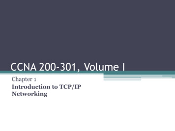
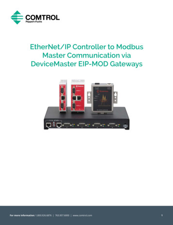
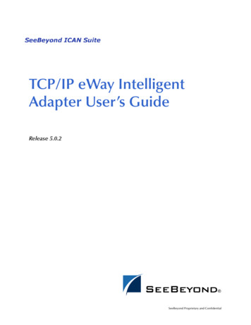
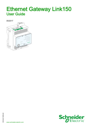
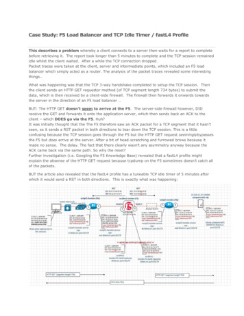
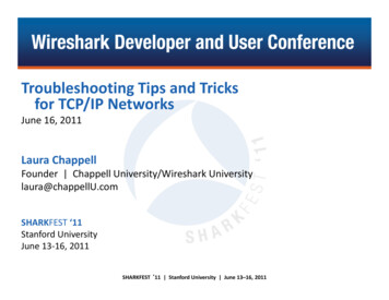
Sreekumari and Chung EURASIP Journal on Wireless Communications and Networking 2011, 1/1/23unneccessarily and hence wasting bandwidth and in thelatter case, the TCP sender not only reduce the size ofcongestion window but also retransmit the packet needlessly. Several loss differentiation algorithms have beenproposed for improving the performance of TCP.Among that TCP NewJersey [4], TCP Veno [5], andTCP CERL [6] have been proposed to differentiate congestion losses from random losses whereas RR TCP [7],TCP PR [8], and TCP DOOR [9] have been proposed todifferentiate congestion losses from packet reordering.However, these algorithms have no unified solution todifferentiate the non-congestion events when the senderreceives three dupacks [10]. When random loss andpacket reordering are co-existed, the number of unnecessary retransmission increases and will have adverseeffects on TCP and its congestion control mechanisms,which deteriorate the poor performance of TCP overwireless networks. As a result, it is an important issue ofTCP to guide the TCP sender for triggering the congestion control algorithms properly by providing a unifiedsolution for non-congestion events in addition to network congestion to improve the performance of TCPover wireless networks.To address this issue, we propose a unified solutioncalled TCP NCE for improving the performance of TCPover wireless networks by reducing the unnecessaryreduction of congestion window size and retransmissions due to non-congestion events. Our unified solution TCP NCE has three schemes.1. NCE-Detection which is used for detecting thenon-congestion events from network congestion bycomputing the queue length of the bottleneck linkusing TCP timestamp based RTT measurement.2. NCE-Differentiation is used for differentiating thenon-congestion events especially random loss frompacket reordering by utilizing the flightsize information of the network with a dynamic delay thresholdvalue.3. NCE-Reaction guides the TCP sender to react tonon-congestion events accordingly by introducing anew retransmission algorithm called ‘RetransmissionDelay’ which delays the packet retransmission uptothe expiration of the dynamic delay threshold value.We evaluated TCP NCE with other TCP schemessuch as TCP Veno, TCP CERL, RR-TCP, TCP PR, TCPNewReno, and TCP DOOR and compared the performance by using the metrics such as end-to-endthroughput, accuracy, and fairness through extensivesimulations using Qualnet 4.5 [11]. Simulation resultsshow that TCP NCE has significant improvement overother popular TCP variants. The rest of this article isorganized as follows. In ‘TCP in wireless networks’Page 2 of 20section, we describe the behavior of TCP in wirelessnetworks. We briefly summarizes the previous works in‘Related work’ section. In ‘TCP-NCE’ section, we introduce TCP NCE and its three schemes. We describe theperformance evaluation of TCP NCE with other TCPvariants in ‘Performance evaluation’ section. Finally,‘Conclusion’ section concludes this article and highlightsfuture works.TCP in wireless networksTCP was designed to provide reliable connectionoriented services between any two end systems on theinternet. The congestion control algorithms of TCP consists of Slow-Start, Congestion Avoidance, Fast Retransmission and Recovery as shown in Figure 1 inconjuction with several different timers.In Slow-Start, the size of congestion window (cwnd)increases exponentially at the sender whereas in Congestion Avoidance algorithm, cwnd increases linearly.Fast Retransmission and Recovery algorithm triggersonly when the sender receives three dupacks. As aresult, when the sender receives three dupacks, traditional TCP assumes that the loss of packets are causedby network congestion. However, when TCP deployedin wireless networks, this assumption is no longer true.This is because in wireless networks non-congestionevents are more common than network congestion.When TCP sender receives three dupacks, the senderhas to consider non-congestion events as shown in Figure 1 in addition to network congestion. If the threedupacks is due to packet reordering then the senderneed not retransmit the packets by reducing the size ofcwnd. On the other hand, if the three dupacks is causedby random loss, the sender has to retransmit the packetwithout reducing the size of cwnd. Below, we discussthe main causes of non-congestion events in wirelessnetworks.Random LossIn wireless networks, the loss of packets are due totransmission errors which is more common than congestion loss. The frequent causes of non-congestionlosses in wireless networks are high bit error rate in thewireless medium, exposed and hidden terminal problems, multipath routing, MAC designs etc. [12]. Packetlosses due to channel collision depend on the numberof contention of nodes.Moreover, in wireless networks, the interferencesbetween neighboring nodes are much higher comparedto local area networks. As a result, the bit error rates ofwireless links are more variable in wireless medium. Asshown in Figure 2, TCP sender transmits packet fromP1 to P5. Among that packet P1 was lost due to transmission error. As a result, the receiver sends three
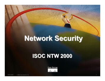
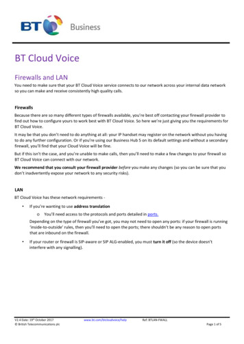
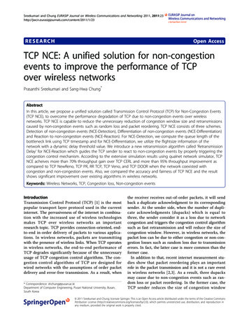
Sreekumari and Chung EURASIP Journal on Wireless Communications and Networking 2011, 1/1/23Page 3 of 20Figure 1 Congestion control algorithms of TCP.dupacks by packets P2 to P4. Upon the arrival of threedupacks the sender trigers fast retransmission unnecessarily and retransmits the packet by reducing the size ofcwnd needlessly and thereby degrade the performanceof TCP.Packet ReorderingPacket reordering [10] refers to the network behavior,where the relative order of packets is altered when thesepackets are transported in the network. As shown inFigure 3, the packets P2, P3, P4, P5, and P1 are sent inthe order of P1, P2, P3, P4, and P5. However, the packetP1 reaches the destination after the arrival of P5. As aresult, the receiver sends three dupacks of packet P1 toFigure 2 Fast retransmisssion due to random packet loss.the sender. Upon receiving the three dupacks of packetP1, the sender trigers fast retransmission and retransmitsthe packet by reducing the size of cwnd needlessly. Inwireless networks, packet reordering may cause due toroute fluttering, inherent parallelism in routers, linklayer retransmissions, router forwarding lulls, multipathrouting etc. TCP inability to distinguish packet reordering from packet loss causes unnecessary retransmissions,slow down the growth of cwnd and reduces the efficiency of the receiving TCP.For delivering information successfully over wirelessnetworks, the modification of TCP congestion controlalgorithms is necessary especially fast retransmissionand recovery. For the higher performance of TCP over
Sreekumari and Chung EURASIP Journal on Wireless Communications and Networking 2011, 1/1/23Page 4 of 20Figure 3 Fast retransmisssion due to packet reordering.wireless networks, the sender not only needs to differentiate non-congestion losses from congestion losses butalso need to differentiate the reordering of packets fromrandom losses as it is not a rare event in wirelessnetworks.Related workIn this section, we describe a set of algorithms that havebeen proposed for improving the performance of TCPthat TCP NCE is compared to in this article. ‘Solutionsfor random loss’ section gives an overview of three random loss solutions and ‘Solutions for packet reordering’section gives an overview of three packet reorderingsolutions. In ‘Other solution’ section, we describe TCPNewReno as it is the most widely deployed protocol incurrent internet.Solutions for random lossTCP Veno differentiate the random losses from congestion losses by adopting the mechanism of TCP Vegas[13] to estimate the size of the backlogged packets (N)in the buffer of the bottleneck link. The calculation of Nis given below.N Diff BaseRTT(1)where Diff is the difference between expected andactual rates and BaseRTT is the minimum measuredround-trip times. The Expected and Actual rates aremeasured as,Expected cwnd/BaseRTT(2)Actual cwnd/RTT(3)where cwnd is the current size of congestion windowand RTT is the measured smoothed round-trip time.TCP Veno used the measurement of N to differentiatethe type of packet loss. Specifically, when a packet islost, Veno compare the measured value of N with b(backlog threshold). If N b, TCP Veno assumes theloss to be random rather than congestive, otherwiseVeno assumes the loss to be congestive.TCP CERL (Congestion Control Enhancement forRandom Loss) distinguishes random losses from congestion losses based on a dynamic threshold value. TCPCERL is a sender side modification of TCP Reno. TCPCERL and TCP Veno are similar in concept. However,the mechanisms utilized by TCP CERL differ greatlyfrom those used in TCP Veno. TCP CERL utilizes theRTT measurements made throughout the duration ofthe connection to estimate the queue length (l) of thelink, and then estimates the congestion status. The calculation of l is as shown below,l (RTT T) B(4)where RTT is the measured round-trip time, B thebandwidth of the bottleneck link, and T the smallestRTT observed by the TCP sender and l is updatedwith the most recent RTT measurement. Using thevalues of l and A (a constant which is equal to 0.55),TCP CERL used to set the dynamic thresholdvalue (N),N A lmax(5)where l max is the largest value of l observed by thesender. If l N when a packet loss is detected via threedupacks, TCP CERL will assume the loss to be randomrather than congestive. Otherwise, TCP CERL willassume the loss is caused by congestion.TCP NewJersey introduced as the extension of TCPJersey [14] as a router assisted solution for differentiating random packet loss from congestion loss and reactaccordingly. TCP New Jersey has two key componentsin its scheme, timestamp based available bandwidth estimation (TABE) and congestion warning scheme. Toestimate the available bandwidth, TCP Jersey follows thesame idea of TCP Westwood’s rate estimator to observethe rate of acknowledged packets by acknowledgments(ack), but with a different implementation. Upon
Sreekumari and Chung EURASIP Journal on Wireless Communications and Networking 2011, 1/1/23receiving n acks, the available bandwidth Bn is estimatedas shown below.Bn δBn 1 Ln(tn tn 1 ) δ(6)where δ is the TCP’s estimation of the end-to-endRTT delay at time t n , L n the size of the data, t n-1 thearrival time of the previous ack, and tn the arrival timeof nth packet at the receiver. The sender interprets theestimated rate as the optimal congestion window (ownd)in unit of the size of segment (S) and is calculated as,ownd (δ Bn ) /S(7)When the sender receives three dupacks, TCP NewJersey checks whether the received ack has congestionwarning mark or not. If it has mark, TCP NewJerseyassumes that the loss is caused by network congestionand proceeds as TCP NewReno [15] after estimating theavailable bandwidth for adjusting the size of cwnd,whereas, if the ack has no mark, TCP NewJerseyassumes the loss is due to non-congestion and retransmits the dropped packet without reducing cwnd.Solutions for packet reorderingRR TCP, the reordering-robust TCP proposed as anextension of the Blanton-Allman algorithms [16]. RRTCP is a sender side solution, which adjust the threshold (dupthresh) of dupacks dynamically to detect andrecover from spurious fast retransmissions. However,this solution differs in three ways compared to BlantonAllman algorithm. First, RR TCP uses a differentmechanism to adjust dupthresh dynamically. The authorutilizes a combined cost function for retransmissiontimeouts (RTO) and false fast retransmissions to adaptthe false fast retransmit avoidance ratio (FA ratio). Second, the authors considered the extended version of thelimited transmit algorithm [17] which permits a sourceto send up to one ack-clocked additional cwnd’s worthof data. Third, for the estimations of RTT and RTO theauthors proposed an idea to correct the sampling biasagainst long RTT samples. Compared to Blanton-Allman algorithm, RR TCP needs excessive computationaland storage overhead.TCP Persistent packet reordering (TCP PR) proposedto improve the poor performance of TCP under persistent packet reordering by delaying solely on timers. Todetect a packet loss, TCP PR maintained timers to keeptrack of how long ago a packet was transmitted insteadof relying dupacks. When TCP PR detects a packetdrop, the sender reduces the size of cwnd into half andcarried out congestion avoidance algorithm. In order toavoid the over-reaction to congestion, TCP PR will notreduce the size of cwnd for subsequent occasionalPage 5 of 20segment drops in the same cwnd. When more than halfof a cwnd’s worth of packets is detected to be lost,cwnd is set to one and triggers the slow start algorithm.One of the major advantages of TCP PR is that it canable to maintain ack clocking in the presence of packetreordering. Another merit is the new RTT and RTOestimator are very effective in packet reordering. However, TCP PR has some limitations. First, TCP PR iscomputationally expensive and second, the new RTTestimator is overly sensitive to spikes in RTT.TCP DOOR (Detection of out-of-order and response)is a state reconciliation method, to solve the performance problems caused by spurious retransmissions andto eliminate the retransmission ambiguity by disablingthe congestion response for a period of time. In orderto detect reorder packets, TCP DOOR insert thesequence numbers of data and acks on each data packets and acks, respectively. Upon the detection of out-oforder events, the sender can either disable the congestion response or trigger congestion avoidance algorithm.TCP DOOR detects out-of-order events only after aroute has recovered from failures. As a result, TCPDOOR is less accurate and responsive than a feed-backbased approach, which can determine whether congestion or route errors occur in a responsive manner.Other solutionTCP NewReno changes the fast retransmit algorithm foreliminating Reno’s waiting time for the retransmissiontimeout when multiple segments are lost within a singlewindow. More than 76% of web servers deployed TCPNewReno as the standard protocol [18]. In fast retransmission, when the sender receives three dupacks thecurrent implementation of TCP NewReno stores thehighest sequence number transmitted in a variable‘Recover’, retransmit the lost segment and set cwnd tossthresh (slow start threshold) plus 3 * mss (maximumsegment size). Then, TCP sender enters into fast recovery and increment cwnd by one mss for each additionaldupacks and transmits new packets, if allowed by thenew value of cwnd and the receivers advertised window.When the sender receives a new ack including Recover,the sender sets cwnd to ssthresh and goes to congestionavoidance state. On the other hand, if this new ack doesnot include Recover, then the sender consider it as apartial ack, retransmit the first unacknowledged segmentand add back one mss to cwnd and send a new segmentif permitted by the new value of cwnd. This way, TCPNewReno can recover multiple packet losses from a single window of data. However, TCP NewReno assumesall duplicate acks are due to the cause of networkcongestion.Opposed to above approaches, TCP NCE is able todetect, differentiate and react to non-congestion events
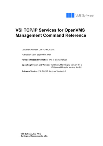
Sreekumari and Chung EURASIP Journal on Wireless Communications and Networking 2011, 1/1/23accurately while maintaining responsiveness againstsituations with purely congestive loss. TCP NCE canincrease the performance of TCP over wireless networksby reducing the unnecessary reduction of cwnd size andspurious retransmissions due to non-congestion events.TCP NCEIn this section, to tackle the end-to-end performancedegradation problem of TCP over wireless networks, weintroduce our unified solution named as TCP NCE,which is capable of reducing the unnecessary retransmissions and reduction of cwnd size by detecting, differentiating, and reacting to non-congestion events whilemaintaining responsivess against situations with purelycongestive loss. In the following subsections, we describethe three schemes of TCP NCE such as NCE-Detection,NCE-Differentiation, and NCE-Reaction.NCE-DetectionFor detecting the non-congestion events from networkcongestion, we measure the queue length of the bottleneck link of a TCP connection. We use a similarmethod to that used in [6] for measuring the queuelength. Compared to former method, the main difference lies in the measurement of RTT. When computingthe queue length, the estimation of RTT is importantbecause RTT includes the delays of forward and reversepaths. In our scheme, we calculate RTT using the timestamp option fields defined in RFC 1323 [19] as shownin Figure 4. The timestamp option contains two fieldsnamely, timestamp (TS) value and timestamp echoreply. Each field has four bytes.When a segment leaves the sender, the field TSvalstores the current time of sending packet. If that segment reaches the receiver, it stores the TSval. When thereceiver sends ack, it attaches the time of previouslyreceived segment in the TSecr field. When the sourcereceives this ack, it takes the TSecr value and use forcalculating the RTT as shown in (8).RTT current time TSecr(8)This way of RTT measurement works correctly in theface of non-congestion events especially in the case ofpacket reordering rather than using an algorithm thatFigure 4 TCP Timestamp options.Page 6 of 20samples one RTT per window of data. The reason is,in the presence of spurious fast retransmits, TCP islikely to have to discard most of its potential samples.As a result, the RTT estimator will not sample theRTT very frequently and may not keep a good estimateof the RTT [20]. By using the measured RTT, we calculated the queue length (Ql) of the bottleneck link asshown in (9),Ql B(RTTnow RTTmin )(9)where RTT now is the current round-trip time whenthe sender receives an ack, RTT min is the minimumRTT observed by the TCP sender, and B is the bandwidth of the bottleneck link. As shown in Figure 5,for detecting the non-congestion events at the time ofreceiving the three dupacks, the sender checks thecurrent queue length which is greater than a threshold value. If it is greater than a threshold value (ThVal), the TCP sender confirms that the dupacks isdue to network congestion and proceeds as TCPNewReno otherwise the sender assumes that thedupacks is due to non-congestion events and delaysthe retransmission upto the expiration of dynamicdelay threshold value.Determination of threshold valueFor determining the threshold value in order to detectnon-congestion events from network congestion, weassume that the router uses drop-tail queueing policy asit is the most widely deployed router queue management scheme [21]. Figure 6 shows the network environment that we considered for determining the thresholdvalue. There are ‘n’ TCP flows from source (S to Sn)connected to the router R1 and the router R2 connectedto the destinations (D to Dn). The congested uplinkfrom R1 and R2 is with capacity C. Based on drop-tailalgorithm, when the queue length becomes equal to thebuffer size (BS), then all the newly arrived packets arebeing dropped. As a result, for determining the threshold value we use the percentage of usage buffer size.However, how much percentage of buffer size we needto use for determining the threshold value for detectingnon-congestion event from congestion? For that, wedivide the router buffer space into three different loads
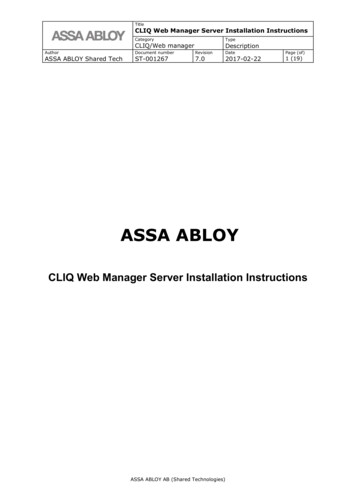
Sreekumari and Chung EURASIP Journal on Wireless Communications and Networking 2011, 1/1/23Page 7 of 20Figure 5 Psuedocode of TCP NCE-Detection of non-congestion events.as shown in Figure 7. It consists of light load, mediumload and heavy load.When the router buffer space is less than 30%We consider it as a light load and the router is not congested at this time. As a result, when the sender receivesthree dupacks, we can predict that the three dupacks isdue to non-congestion events.When the router buffer space is less than 90% andgreater than 30%We consider it as a medium load and the router is notcongested at this time, but it is easy to become congested at the next period of time. In this case also, wecan assume that the arrival of three dupacks is due tonon-congestion events.When the router buffer space is greater than 90%It means that the router is in the heavy load and it isunder congestion at this time and the buffer will easilyoverflow, which results the packet loss due to networkcongestion.Furthermore, for fixing the threshold value we didexperiments by using different buffer loads in terms ofaccuracy as it is the most important performance metricof both events. Because when accuracy of non-Figure 6 Network environment.congestion event increases, obviously the TCP performance also increases [22-24] compared to traditionalTCPs. The topology we used for our experiments asshown in Figure 6. We use TCP connection with 3%random packet loss and 1% packet reordering with bottleneck capacity 6 Mbps and propagation delay 10 ms.We measured the accuracy of non-congestion events(NCEaccuracy) using equation (10),NCEaccuracy NCPexact /NCPtotal(10)where NCP exact is the number of non-congestionpackets exactly identified as non-congestion events andNCPtotal is the total number of non-congestion packetscaused by transmission errors and packet reordering.Figure 8 shows the result of accuracy for varying bufferloads. It is evident that when buffer load increases upto90%, the accuracy of non-congestion event becomeshigher. On the other hand, when the buffer load isgreater than 90%, the accuracy of non-congestion eventdecreases. Because when the buffer becomes full, all theincoming packets may drop. As a result, if more thanone TCP connection, all the sender receives threedupacks and the sender assumes that the packet loss aredue to network congestion even in non-congestionevents and thereby decrease the accuracy. As a result, inorder to use the buffer resources fully, we set the
Sreekumari and Chung EURASIP Journal on Wireless Communications and Networking 2011, 1/1/23Figure 7 Different buffer loads.threshold value which is equal to 90% of the buffer size.Moreover, this value has another advantage. That is,when the queue length becomes greater than 90% at thetime of receiving three dupacks, we reduce the size ofcwnd and can avoid the loss of multiple packet dropsfrom different TCP sources due to network congestion.NCE-DifferentiationWhen the sender detects three dupacks is the cause ofnon-congestion event, the sender of TCP NCE computes a dynamic delay threshold (delay-thresh) for differentiating whether the received dupacks are due torandom packet loss or packet reordering and delays theretransmission upto the expiration of delay-thresh. Forcomputing the delay-thresh, we need to consider threethings.(1) If the value of delay-thresh is high, then retransmission timeout happens and the packet gets retransmitted by reducing the size of cwnd to one.(2) If the value of delay-thresh is too small, then theTCP will continue to retransmit packets unnecessarily.(3) If the value of delay-thresh is too high, retransmission may not triggered leading to retransmissiontimeout.Page 8 of 20As a result, by considering these things TCP NCEcomputes the best value of delay-thresh by utilizing theflightsize information of the network. Let ‘PackLSent’ bethe last sent packet from the source and ‘PackLAck’ bethe last acknowledged packet from the receiver. Thenthe total number of outstanding packets ‘PackTotNum’ inthe network at the time of receiving dupacks is calculated as shown below,PackTotNum PackLSent PackLAckFrom the total number of outstanding packets in thenetwork, the sender receives three dupacks. That meansthree more packets that has left the network, then theremaining packets in the network ‘PackRemain’ is,PackRemain PackTotNum ndupacksdelay - thresh PackRemain(13)When the sender receives add-dupacks in addition tofirst three, which is greater than or equal to the value ofPackRemain, then that add-dupacks are the sign of newlysent packets. As a result, the TCP sender can confirmsthat the corresponding packet is lost from the old window of data due to transmission errors. Otherwise, thesender confirms that the add-dupacks were due to reordered packets because if the packet is reordered fromAccuracy Packets302520151052040(12)After receiving ndupacks which is equal to three, thesender can expect this much of additional dupacks (adddupacks) from the receiver. As a result, we can set thevalue of delay-thresh as,4035(11)60Loads (%)Figure 8 Accuracy of detecting non-congestion events with different buffer loads.80100
Sreekumari and Chung EURASIP Journal on Wireless Communications and Networking 2011, 1/1/23Page 9 of 20Figure 9 Psuedocode of TCP NCE Reaction of detecting non-congestion events.one window of data, the reordered packet may reach thedestination before the packets from new window of datareaches the destination [25]. Not only that, the timetaken to reach the newly sent packet to the destinationis much higher than the arrival of the reordered packetat the destination [26]. As a result, our delay thresholdvalue helps the TCP to avoid unnecessary retransmissions and reduction of cwnd.NCE-ReactionWhen the sender receives three dupacks and the currentqueue length is less than the threshold value, then thesender assumes that these dupacks are the sign of noncongestion events. In this si
To address this issue, we propose a unified solution called TCP NCE for improving the performance of TCP over wireless networks byreducing the unnecessary reduction of congestion window size and retransmis-sions due to non-congestion events. Our unified solu-tion TCP NCE has three schemes. 1. NCE-Detection which is used for detecting the