Transcription
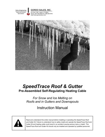
112SECTIONRoofsROOF STRUCTURESMODULE 3SHEET 5Roof StructuresTypes of roof structureTraditional roofs can be divided into three main types of structure: Single roofs. Double roofs. Trussed roofs.Modern construction methods make use of another type of roof structure and this is knownas trussed rafter roofs (see trussed rafter roofs).Single roofDouble roofTrussed roofTrussed rafter roof
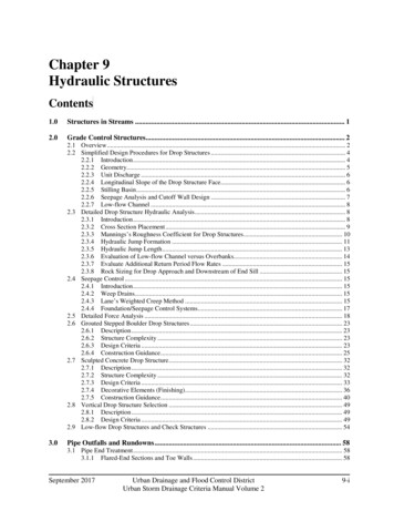
12SECTIONMODULE 3SHEET 6RoofsROOF STRUCTURESSingle roofsRafters of single roofs do not require any intermediate support. This type of roof hasa number of limitations. It can only be used for small spans. If greater spans are required,larger roof sections would be needed. If the feet of the rafters are not tied together bymeans of a binder or roof joist, then this type of roof will have a tendency, under weight,to push the supporting walls outwards at the top causing structural failure of the walls.Single roofs can be categorised as follows:Couple roof – These can be used for building with a clear span of not greater than 3m andpitches less than 40º.Collar roof – These can be used for buildings with a clear span not exceeding 4mm.Close couple roof – These can be used for buildings with a clear span not exceeding5.5mm and with pitches less than 25º.Couple roofThis type of roof structure is very limited in its use. The roof consists of common raftersfixed at the ridge and at the wall plate. When subjected to any type of load or force actingvertically downwards the rafters will move outwards at their feet thus exerting thrust to thewalls forcing them outwards and causing possible failure of the wall structure.Couple roofCouple roof under pressure
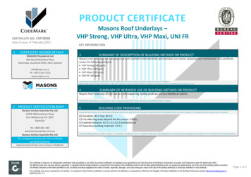
112SECTIONRoofsMODULE 3SHEET 7ROOF STRUCTURESCollar roofA collar roof incorporates a horizontal roof member positioned approximately one thirdof the distance from the ridge to the wall plate line. This extra roof member helps preventthe rafters from spreading when under load; this allows this type of roof structure to beused for greater spans than the couple roof. This design also gives a greater ceiling heightif required.Collar roofClose couple roofClose couple roofThis roof incorporates a main tie which is secured to the feet of each rafter and spansthe width of the building. This added member forms a triangle which introduces thetriangulation of forces within the structure. To stop the ceiling joist from sagging, a hangeris fixed to the rafter at the top and the ceiling joist at the bottom.To further increase the strength of this structure, a binder is fixed to each ceiling joist andhanger. This binder runs parallel with the main wall and at right angles to the ceiling joist.This type of structure ensures that this type of roof can be used for great spans without thefear of the roof spreading under loads.
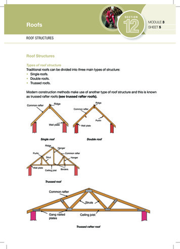
12SECTIONMODULE 3SHEET 8RoofsROOF STRUCTURESPitches, Spans and RisesWhen setting out a roof, there are certain essential factors that must be considered.These are:Roof span – This is the distance across the roof and measured to the outer edges of thewall plates.Roof height or rise – This is the vertical height of the roof at its highest point and ismeasured from the top of the wall plates to the intersection of the rafters at the top of theroof. When measuring rafters, the length is taken as a straight line running through thecentre of the rafter.Roof pitch – This is the angle or slope of the roof and can be expressed in degrees or as afraction or ratio found by dividing the rise by the span.Example. If a roof has a span of 6m and a rise of 3m then the pitch would be:Pitch Rise 3 Span61 pitch2Since the rise is half the span, the angle of the roof would be 45 .Definitions of terminology of a gable roof
112SECTIONRoofsMODULE 3SHEET 9ROOF STRUCTURESCommon Rafter Length and BevelsWhen determining the lengths and bevels of common rafters, it is normal to consider themas single lines rather than rafters of a certain width or thickness. If the rise and the span areknown, it is a simple procedure to determine the length of the common rafter and its mainbevels.The roof section can be set out full size or to scale. Once the section has been set out thelength of the common rafter can be determined by drawing the rise and the span as a rightangle joined together by the hypotenuse which will determine the slope of the roof.The rafter is seated upon the wall plate by means of a notch or birdsmouth joint which iscut one third into the rafter. The angle at which the notch is cut is called the seat cut. Thetop angle or bevel is called the plumb cut.Once the bevels have been determined, a sliding bevel can be set to the angle required orin some cases, a piece of plywood can be cut to each bevel and used as a template for allthe other rafters.When determining the length of the rafter, an allowance is made for the thickness of theridge and the length of the overhang at the eaves.Determining the length and bevels of a common rafter
12SECTIONMODULE 3SHEET 10RoofsROOF STRUCTURESVerge Details and Ladder FrameThe construction of the verge of a gable roof is shown below. The roof extends over thegable wall to give a suitable overhang. To achieve this is a simple frame called a ladderframe is constructed. This frame consists of the last two rafters joined together by means ofnoggings nailed to the inside of the rafters. The brickwork of the gable extends through thisframe to finish the wall level with the top of the rafters.A finishing trim called a barge board is then nailed to the last rafter. This barge board issufficiently wider than the rafters to cover the entire end rafter including the tilting fillet.A soffit is then fixed to the underside to match the soffit under the eaves. The barge boardis also fixed to the fascia. The fascia can be mitred to the barge board at the foot while thetop of the barge board at the apex of the roof is mitred to the matching barge board on theother side.
112SECTIONRoofsMODULE 3SHEET 11ROOF STRUCTURESEaves Details and FasciasThere are various ways of constructing the eaves of a gable roof. Below are two examples: Flush eaves. Boxed or closed eaves.Flush eaves detailsClosed or boxed eaves details
12SECTIONMODULE 3SHEET 12RoofsROOF STRUCTURESFlush eavesIn this method of finishing off the lowest edge of the roof, the rafter feet are cut plumb, andproject 25mm from the face of the outer brickwork. This will allow a ventilation gap to beformed so that a continuous flow of air can circulate throughout the roof space.The fascia board is nailed directly to the rafter feet to form a face trim. It is to this fasciaboard that the guttering is fixed.Closed or boxed eavesThis is a more complex method of finishing the lowest edge of the roof. The rafter feetare allowed to overhang the face of the outer brickwork. The overhang can vary in sizebut usually the distance is stipulated on the working drawings, or is at a distance that canaccommodate a proprietary ventilation soffit.The soffit is supported by a cradling bracket or, in some cases, a piece of plywood cutto shape.The roof space can be ventilated by using a proprietary vermin proof ventilation strip or thesoffit can be drilled with a series of holes into which plastic ventilators are fixed.Roof ventilationRoof ventilation is essential to reduce the likelihood of condensation within the roof spaceas required by the Building Regs 1985.The regulations state that all roofs must be cross-ventilated at eaves level by permanentvents and these must have an equivalent area equal to a continuous gap along both sidesof the roof of 10mm, or 25mm where the pitch of the roof is less than 15 .This ventilation requirement can be achieved by: Leaving a gap between the outer wall and the soffit. Using a proprietary ventilation strip. Using circular plastic ventilators set into the soffit board.There are many types and designs of proprietary ventilators available all of which have beendesigned to give sufficient ventilation to the roof space if used and incorporated into thestructure correctly.
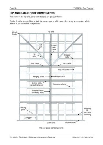
112SECTIONRoofsMODULE 3SHEET 13ROOF STRUCTURESDouble RoofsA double roof is a roof whose rafters are of such a length that they require an intermediatesupport. This support is usually a beam which is secured under the rafters at a point halfway between the ridge and the wallplate. This beam is known as a purlin.In gable roofs, the purlin is built into the gable wall to provide added support. In doublepitched roofs, the purlin is fixed to the rafters in a continuous length, jointed at all theinternal and external corners of the roof.In traditionally constructed roofs, the roof may also require added support in the form ofroof trusses. This will depend upon the size of the roof and the type of roof covering theroof has to support.In modern double roof construction, the whole of the roof is constructed of lightweight rooftrusses called trussed rafters (See Module 4).Double roof with hipped endThere are many designs and combinations of double roofs. The design of the roof willdepend upon the size and shape of the ground floor plan of the building.The drawing shows a partly hipped roof with one hipped end and one gable end. A fullyhipped roof has no gables, and the eaves run round the perimeter of the roof. The eaves areusually of the boxed or enclosed type.Hipped and gable roof components and terminology
12SECTIONMODULE 3SHEET 14RoofsROOF STRUCTURESValley construction using lay boardAlternate valley construction using valley rafter
112SECTIONRoofsMODULE 3SHEET 15ROOF STRUCTURESKeskillStudent Key SkillApplication of NumberSetting out and determining roof bevelsThere are a number of ways that the length and angle of members can be determined.The roof pitch is always defined in degrees while the lengths of the members are definedin metres.Since all roof member bevels are based on the right angle triangle principle, they can bedetermined by: The use of scaled drawings in orthographic projection. The use of a roofing square (simple tool based on the right angle principle and calibratedin degrees and millimetres and the length of inclined roof members).Determining roof member lengths and bevels using orthographic projection.Development of sloping roof surfaces on a hipped roof
12SECTIONMODULE 3SHEET 16RoofsROOF STRUCTURESStudent Key SkillApplication of NumberDetermining roof member lengths and bevels using orthographic projectionRoofing angles and true lengthsThe geometry to determine the length and bevels of each individual roof member will becovered in more detail with your trainer.
112SECTIONRoofsMODULE 3SHEET 17ROOF STRUCTURESStudent Key SkillApplication of NumberDetermining roof member lengths and bevels using a roofing square.A roofing or framing square is a steel square which consists of two arms set at right anglesto each other. One of the arms is wider and longer than the other; this is known as theblade. The shorter, thinner arm is known as the tongue.The length of the blade is 620mm and the tongue 450mm.The square is calibrated in millimetres and degrees, and both sides contain a set of tableswhich give the rafter and hip lengths in metres run for various rises in degrees.Steel roof squareTo use the square, the rise of the roof is set on the tongue, and the run of the rafter is set onthe blade.Example. Consider a common rafter of a roof with a rise of 3m and a rafter run of 4.50m.To accommodate the use of the square, the sizes are scaled down or reduced by.Therefore:Rise 3.00m 10 300mmRun 4.50m 10 450mmSteel roofing square with adjustable fence
12SECTIONMODULE 3SHEET 18RoofsROOF STRUCTURESStudent Key SkillApplication of NumberUse of steel roofing squareBelow is an example of how the square is applied. The lengths will be to scale and will needto be converted to full size.The drawing shows how the length and angles are set off for a common rafter. The sameprocedure can be used to obtain all the other rafter lengths and angles using thefollowing combinations. Common rafter run common rafter run Hip run. Hip run rise Hip length and cuts. Hip length rise Hip backing bevel. Hip length hip run Hip edge cut. Common rafter length common rafter run Purlin edge cut. Common rafter length rise Purlin side cut.
The roof space can be ventilated by using a proprietary vermin proof ventilation strip or the soffi t can be drilled with a series of holes into which plastic ventilators are fi xed. Roof ventilation Roof ventilation is essential to reduce the likelihood of condensation within the roof space as required by the Building Regs 1985.