Transcription
CITATION MUSTANG OPERATING MANUALCHAPTER 8FIRE PROTECTIONINTRODUCTIONThis chapter describes the fire protection system on the Citation Mustang aircraft. The engine fire-detection system consists of two separate detection circuits (one for each engine),which provide visual warnings. The engine fire-extinguishing system includes one fire bottle, which is activated from the cockpit. A portable fire extinguisher is in the cabin.GENERALThe fire-protection system consists of enginefire detection, engine fire extinguishing, aportable fire extinguisher, and aircraft construction that reduces a fire risk. The enginefire-detection system detects fires and overheatconditions in the engine nacelles and alertsthe crew. The engine fire-extinguishing systemsuppresses those fires upon pilot command bysupplying fire-extinguishing agent.For additional protection, the engine nacellefire zone is separated from the pylon and therest of the aircraft by a stainless steel firewall. At the firewall penetrations and in the nacelle, fuel is contained in stainless steelfittings, stainless steel tubes, and fire-resistanthoses.The rotary TEST knob on the instrument panelis used to test the fire warning system.Fire suppression in the cabin area is accomplished using a portable fire extinguisher.510OM-008-1
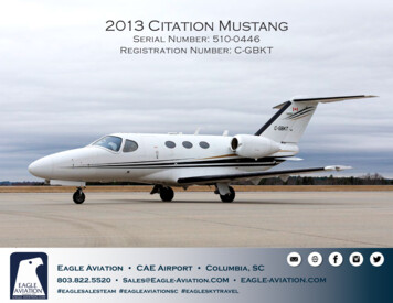
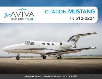
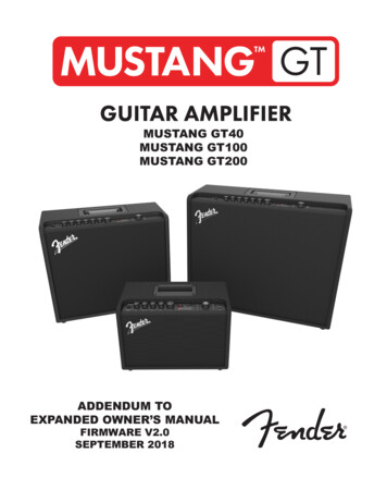
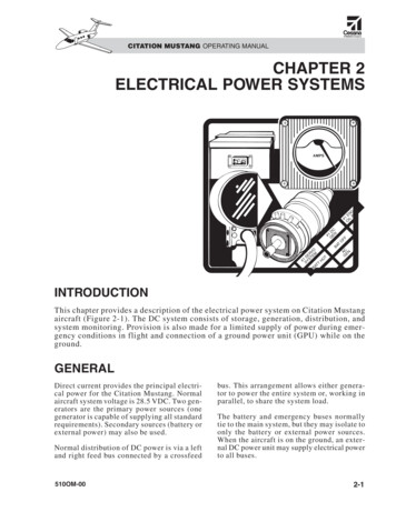
CITATION MUSTANG OPERATING MANUALDESCRIPTIONPORTABLE FIREEXTINGUISHERENGINE FIRE DETECTIONSYSTEMA portable fire extinguisher provides fire protection inside the aircraft.The engine fire-detection system consists of: Fire-detection loopCOMPONENTS Pressure sensor Red L and R ENGINE FIRE lightsExcessive heat by fire or other heat sources expands inert gas inside the fire-detection loop.The expansion of gas closes a pressure switchthat sends a signal to illuminate the left orright ENGINE FIRE light.The fire-detection system requires DC power.FIRE DETECT circuit breakers for the independent sides are on the left and right CB panels within the ENGINE SYSTEMS grouping.ENGINE FIRE-EXTINGUISHINGSYSTEMThe single bottle engine fire-extinguishingsystem enables the flightcrew to suppress a firein the left or right engine compartment. Thisaction is limited to one use.The engine fire-extinguishing system consists of: Engine fire bottle assembly Distribution tubes Nozzles in each engine nacelle BOTTLE ARMED lights Fuel shutoff valve and generator disconnectThese components shut off the generator andfuel supply as well as discharge extinguishingagent, which is pressurized with nitrogen anddischarged by electrically activated cartridgesto the engine nacelles.8-2FIRE DETECTION LOOPEach fire detection loop detects a fire or overheat condition in the respective engine compartment (Figure 8-1). The tube routes alongboth sides of the engine.An increase in temperature on any part of thetube increases the pressure of the gas (helium)inside the tube.If the tube develops a leak, normal pressurevents and closes the test pressure switch; thisis indicated by L and R ENGINE FIRE lightsnot illuminating when the rotary TEST knobis placed in the FIRE WARN position.PRESSURE SENSORA pressure sensor is at the end of the fire-detection loop. When the loop is heated by fireor a bleed-air leak, the gas in the tube expands, activating the pressure sensor. Thisproduces an electrical signal that provides awarning to the flightcrew. The signal is in theform of: L or R ENGINE FIRE lights MASTER WARNING lightsENGINE FIRE BOTTLEASSEMBLYThe engine fire bottle (with two squibs) is in thetail compartment. It can be used to extinguisha fire in either engine nacelle (Figure 8-2). Thefire bottle contains enough extinguishing agentto protect against one engine fire (0.85 poundof Halon 1301 extinguishing agent).510OM-00
510OM-00DISCHARGE AGENTHELIUMLEGENDPGAUGEFUSIBLEPLUGBOTTLEPFigure 8-1. Engine Fire-Detection and Extinguishing SystemFIRE DETECTION LOOP(HELIUM-FILLED TUBE)SQUIBSQUIBCONTROLBOXESCITATION MUSTANG OPERATING MANUAL8-3
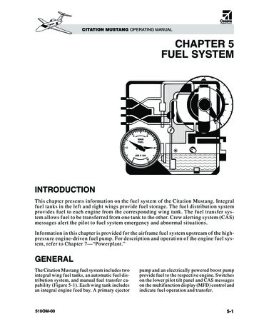
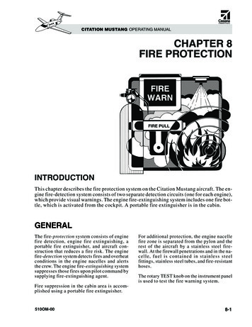
CITATION MUSTANG OPERATING MANUALFigure 8-2. Engine Fire BottleThe fire-extinguisher bottle contains two individual firing cartridges (squibs). The cartridges are connected to distribution tubes thatare routed to the left and right engine compartments. The bottle has a safety relief valvethat thermally relieves (discharges) its contentsinto the tail cone if the internal bottle temperature rises above 210 F.FUEL SHUTOFF VALVE ANDGENERATOR DISCONNECTThe firewall shutoff valve closes and electrical flow from the generator is stopped when anilluminated ENGINE FIRE light is pushed.An amber F/W SHUTOFF L-R message in thecrew alerting system (CAS) window indicatesthat the fuel shutoff valve is fully closed. Whenthe generator is disconnected, the respectiveGEN OFF message appears in the CAS window.PORTABLE FIREEXTINGUISHEROne portable handheld fire extinguisher is ina drawer in the cabinet behind the pilot (Figure8-3). It is accessible from either the pilot,copilot, or passenger positions. The Halon1301 type extinguishing agent discharges asa vapor with no residue or decrease in visionto personnel. The discharge distance is approximately 9–15 feet with a discharge timeof 10 seconds.8-4Figure 8-3. Portable Fire ExtinguisherCONTROLS ANDINDICATIONSENGINE FIRE LIGHTSRed L and R ENGINE FIRE lights are on theupper part of the center instrument panel(Figure 8-4). They respond to signals from therespective engine fire sensors. Each light is covered by a spring-loaded, transparent plasticguard and has an integral pushbutton switch.If the red L and/or R ENGINE FIRE light illuminates steady, it indicates a fire or overheatcondition in the corresponding engine.MASTER WARNING LIGHTSThe MASTER WARNING lights are on theinstrument panel above each primary flightdisplay (PFD). The MASTER WARNINGlights illuminate flashing when the L or RENGINE FIRE lights illuminate. The pilotacknowledges by pressing one of the MASTER WARNING lights. Pressing will extinguish both lights.WHITE BOTTLE ARMEDLIGHTSA white BOTTLE ARMED light is below eachred ENGINE FIRE light on the upper-centerpanel (Figure 8-4). Each BOTTLE ARMEDlight has an integral pushbutton switch.510OM-00
CITATION MUSTANG OPERATING MANUALFigure 8-4. ENGINE FIRE and BOTTLE ARMED LightsThese lights indicate when the bottle is armedfor the respective engine and prepared to release extinguishing agent. After the extinguishing agent is released, the lightextinguishes, indicating to the crew the extinguisher bottle is empty and is no longeravailable for use.CAS MESSAGESGEN OFF L-RWhen either of the ENGINE FIRE lights arepushed, the respective amber GEN OFF message appears in the CAS window.ENGINE FIRE lights is an indication the warning system is working properly.NOTEA successful test of the fire-detectionsystem using the rotary TEST knob,or illumination of either BOTTLEARMED light, does not confirm thatthe fire bottle is serviced and full.This can only be confirmed by a visual check of the bottle gauge andcomparing the reading to a placardthat correlates the acceptable pressure/temperature ranges.F/W SHUTOFF L-RWhen either of the ENGINE FIRE lights arepushed, the respective amber F/W SHUTOFFmessage displays in the CAS window. This indicates that the corresponding fuel shutoffvalve is closed.OPERATIONPREFLIGHTRotary TEST KnobTest the engine fire-detection system beforeeach flight by using the rotary TEST knob(Figure 8-5) during the preflight inspection.This test verifies connections to the fire bottles and warning system. Illumination of both510OM-00Figure 8-5. Rotary TEST Knob8-5
CITATION MUSTANG OPERATING MANUALPortable Fire ExtinguisherDuring preflight, check that the portable fireextinguisher is serviced and secure. Verifythat the pressure gauge on the extinguisherindicates in the green arc and that the extinguisher is secure in its drawer behind thepilot seat.Engine Fire Bottle InspectionAn inspection door is in the aft compartmentto view the fire bottle gauge. A placard is onthe back of the door. Check that the gaugepressure matches the acceptable ranges basedon outside air temperature (OAT). Refer tothe Normal Procedures Checklist.CAUTIONThe white BOTTLE ARMED lightdoes not illuminate (and cannot operate) until after the correspondingred L or R ENGINE FIRE light hasbeen pressed.NOTEIf a crewmember presses the otherBOTTLE ARMED light, which isnot illuminated, the fire bottle doesnot discharge, and no extinguishingoccurs.IN FLIGHTWhen the pilot pushes the illuminated whiteBOTTLE ARMED light, the light extinguishes.Refer to approved Airplane Flight Manual(AFM) checklist. Pushing the L ENGINE FIREor R ENGINE FIRE light:Portable Fire Extinguisher Provides power to the fuel shutoff valve,which cuts off the fuel supply to the affected engine. The amber F/W SHUTOFF L-R message appears in the CASwindow. Disconnects the starter-generator onthe affected engine. The amber GENOFF L or R message appears in the CASwindow. Arms the engine fire bottle squib (explosive cartridge) that routes extinguishing agent to the selected engine.However, the bottle contents do not yetdischarge into the engine. (The corresponding white BOTTLE ARMED lightilluminates.)The BOTTLE ARMED light illuminates toindicate the fire bottle is armed and ready tosupply fire-extinguisher agent to the affectede n g i n e . P u s h t h e i l l u m i n a t e d B OT T L EARMED light to release the agent into the engine and cowling area to extinguish the fire.The single fire bottle is fully released to extinguish the fire.8-6CAUTIONIf smoke or fire is present, immediately don oxygen masks and smokegoggles, and set oxygen to 100%.Ensure that passengers have supplemental oxygen.To operate the portable fire extinguisher, openthe top cabinet drawer and remove extinguisher, hold the extinguisher upright, andaim the extinguisher at the base of fire. Usingthe attached ring, pull the pin from the extinguisher.Squeeze the handles of the extinguisher together to release the extinguishing agent. Spraythe extinguishing agent using a side-to-sidemotion while aiming at the base of the fire.Anytime the extinguisher is used, even partially, maintenance is required before further dispatch.510OM-00
CITATION MUSTANG OPERATING MANUALEMERGENCY/ABNORMALFor specific information on emergency/abnormal procedures, refer to the appropriate abbreviated checklists or the FAA-approved AFM.510OM-008-7
This chapter describes the fire protection system on the Citation Mustang aircraft. The en-gine fire-detection system consists of two separate detection circuits (one for each engine), which provide visual warnings. The engine fire-extinguishing system includes one fire bot-tle, which is activated from the cockpit.