Transcription
Ford Mustang via OBDII Connection
Ford Mustang – OBDII ConnectionECU Technical DocumentationRelease 1.00INTRODUCTIONAIM has developed special applications for many of the most common ECUs: by specialapplications we mean user-friendly systems which allow to easily connect your ECU to ourhi-tech data loggers: user need only to install harness between the logger and the ECU.Once connected, the logger displays (and/or records, depending on the logger) values likeRPM, engine load, throttle position (TPS), air and water temperatures, battery voltage,speed, gear, lambda value (air/fuel ratio), analog channels etc All AIM loggers include – free of charge – Race Studio 2 software, a powerful tool toconfigure the system and analyze recorded data on your PC.Warning: once the ECU is connected to the logger, it is necessary to set it in thelogger configuration in Race Studio 2 software.Select Manufacturer “Ford” and Model (depending on own car model – refer to“Communication protocols” Chapter).Moreover refer to Race Studio configuration user manual for further informationconcerning the loggers configuration.1www.aim-sportline.com
Ford Mustang – OBDII ConnectionECU Technical DocumentationRelease 1.00INDEXChapter 1 – Car Models . 3Chapter 2 – OBDII CAN Communication Setup . 3Chapter 3 – OBDII position . 4Connections to AIM loggers . 5Chapter 4 – Ford communication protocols. 64.3 – Ford Mustang FR500C communication protocol . 64.3 – Ford Mustang FR500C MS communication protocol . 74.5 – Ford Mustang 2005-2009 communication protocol . 84.5 – Ford Mustang 2010 communication protocol . 92www.aim-sportline.com
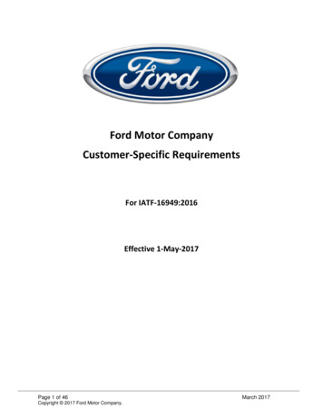
Ford Mustang – OBDII ConnectionECU Technical DocumentationRelease 1.000Chapter 1 – Car ModelsFord ECU is installed on the following car models: Ford Mustang FR500CFord Mustang FR500C MSFord Mustang 2005/2009 - all modelsFord Mustang 2010 - all models4Chapter 2 – OBDII CAN Communication SetupIn all Ford models listed in the previous chapter (ECU communicates On BoardDiagnostic values to AIM loggers through the CAN bus (ISO 15765/4) communicationprotocol. It works with EVO4, MXL, EVO3, XGLog, ECU Bridge, using OBDII standardconnectorOBDII standard connector and its pinout are (see below):PinFunction2Bus positive Line of SAE-J18504Chassis Ground5Signal Ground6CAN (ISO 15765-4 and SAE J2234)7K Line of ISO 9141-2 and ISO 14230-410Bus negative Line of SAE-J185014CAN – (ISO 15765-4 and SAE-J2234)15L line of ISO 9141-2 and ISO 14230-416Battery voltage3www.aim-sportline.com
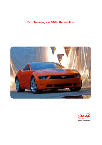
Ford Mustang – OBDII ConnectionECU Technical DocumentationRelease 1.001Chapter 3 – OBDII positionOBDII connector position depends on the car model.The scheme below shows some of the most common OBDII connector position.LocationDescriptionDriver’s side, underneath dashboard, in the area under the steering column, and150 mm (i.e., /-6 inches on either side of the steering column).Driver side, underneath dashboard, between the driver- side door and steeringcolumn area.Driver side, underneath dashboard, between the steering column area and the centerconsole (also includes connectors on the driver side but connected to the centerconsole).Driver’s side, dashboard instrument/gauge area, between the steering column andthe center console.Driver’s side, dashboard instrument/gauge area, between the steering column andthe center consoleCenter console , vertical surface (i.e. near radio and climate controls), left of thevehicle centreline.Center console, vertical surface right of the vehicle centreline or on passenger side ofcenter console.Center console, horizontal surface (i.e. armrest , and brake area) in front passengerareaAny location other than locations #1-8 (i.e. rear passenger area, passenger sideglove box, top of dashboard near windshield)Note: some manufacturers use covers to protect the integrity of the connector. Forfurther information it is suggested to ask to the dealer where OBDII connector issituated on the vehicle.4www.aim-sportline.com
Ford Mustang – OBDII ConnectionECU Technical DocumentationRelease 1.002Connections to AIM loggersTo connect Ford vehicles to AIM loggers: connect the cable labelled CAN of the logger to pin 6 of the OBDII portconnect the cable labelled CAN- of the logger to pin 14 of the OBDII portWarning :OBDII is not powered by the vehicle master switch, so if AIM logger isconnected to OBDII for a long time the battery runs down. The communicationworks only if the dashboard is switched on.5www.aim-sportline.com
Ford Mustang – OBDII ConnectionECU Technical DocumentationRelease 1.003Chapter 4 – Ford communication protocolsDepending on the car model there is a different selection to configure the logger (refer tothe appropriate paragraph for more detail about the correct configuration).54.3 – Ford Mustang FR500C communication protocolTo configure Ford Mustang FR500C select the following ECU model “FR500C”Channels received by AIM loggers connected to Ford Mustang FR500C ECU are:IDCHANNEL NAMEFUNCTIONECU 1FR500C RPMRPMECU 2FR500C WHEELSPEEDWheel speedECU 3FR500C LOADEngine loadECU 4FR500C DESIRED LAMBDADesired lambda valueECU 5FR500C WATERTEMPEngine coolant temperatureECU 6FR500C FUELPRESSFuel pressureECU 7FR500C BATTVOLTBattery supplyECU 8FR500C TPSThrottle position sensorECU 9FR500C LH LAMBDALeft bank lambda valueECU 10FR500C AIRTEMPIntake air temperatureECU 11FR500C EXHAUST TEMPExhaust temperatureECU 12FR500C RH LAMBDARight bank lambda valueECU 13FR500C TRANS TEMPTransmission box temperatureECU 14FR500C GEAREngaged gearECU 15FR500C SYNC LEVELSync. Level6www.aim-sportline.com
Ford Mustang – OBDII ConnectionECU Technical DocumentationRelease 1.0064.3 – Ford Mustang FR500C MS communication protocolTo configure Ford Mustang FR500C MS select the following ECU model “FR500C MS”Channels received by AIM loggers connected to Ford Mustang FR500C MS ECU are:IDCHANNEL NAMEFUNCTIONECU 1MS ENG SPDRPMECU 2MS VEH SPDSpeedECU 3MS ACC PDL POSPedal Position SensorECU 4MS WHL SPD FLWheel speed front leftECU 5MS WHL SPD FRWheel speed front rearECU 6MS WHL SPD RLWheel speed rear leftECU 7MS WHL SPD RRWheel speed rear rightECU 8MS GEAR PS ACTEngaged GearECU 9MS ABS TELTALAbs alertECU 10MS TYRE SZTyre sizeECU 11MS ENG COOL TEngine Coolant TemperatureECU 12MS LOADEngine loadECU 13MS DESI LAMBDALambdaECU 14MS RH LAMBDALambdaECU 15MS LH LAMBDALambdaECU 16MS AIR CH TEMPAir Charge TemperatureECU 17MS CPS SYNCChamshaft / Cranckshaft position sensorECU 18MS FUEL PRESSFuel pressureECU 19MS BATT VOLTBattery VoltageECU 20MS ZE FR TYRETyreECU 21MS ZE RR TYRETyreECU 22MS MAF VOLTManifold Air Flow VoltageECU 23MS AIR FWMass Air flowECU 24MS INJ PW MsInjection PowerECU 25MS IAC DCIdle Air Control (digital value)7www.aim-sportline.com
Ford Mustang – OBDII ConnectionECU Technical DocumentationRelease 1.0074.5 – Ford Mustang 2005-2009 communication protocolTo configure Ford Mustang 2005-2009 select the following ECU Model ”Mustang 2005/09”Channels received by AIM loggers connected to Ford Mustang 2005-2009 ECU are:IDCHANNEL NAMEFUNCTIONECU 1M RPMRPMECU 2M SPEEDSpeedECU 3M PEDAL POSPedal position sensorECU 4M WH SPD FLFront left wheel speedECU 5M WH SPD FRFront right wheel speedECU 6M WH SPD RLRear left wheel speedECU 7M WH SPD RRRear right wheel speedECU 8M TENGINEEngine temperatureECU 9M ETC TELTALEngine Traction control tell taleECU 10M TBO BSTTurbo boostECU 11M FUEL LEVFiltered fuel levelECU 12M FUEL I 1Instant fuel level sensor 1ECU 13M FUEL I 2Instant fuel level sensor 2ECU 14M FUEL AVEFuel average levelECU 15M FFLUXFuel fluxECU 16M CLCH SWClutch switchECU 17M TCS BRKTraction control brake switchECU 18M TCS ENGTraction control engine switchECU 19M BRK SWBrake switchECU 20M ABS TELTALABS tell taleECU 21M AXLE RATIO RRear axle ratioECU 22M MIL TELTALMalfunction indicator lampECU 23M FAILSAFE COOLFailsafe coolant tell taleECU 24M GEAREngaged gearECU 25M TYRETyre revs per kmECU 26M SMART ALSmart alarm8www.aim-sportline.com
Ford Mustang – OBDII ConnectionECU Technical DocumentationRelease 1.0084.5 – Ford Mustang 2010 communication protocolTo configure Ford Mustang 2010 select the following ECU Model “Mustang 2010”Channels received by AIM loggers connected to Ford Mustang 2010 ECU are:IDCHANNEL NAMEFUNCTIONECU 1F RPMRPMECU 2F SPEEDSpeedECU 3F PEDAL POSPedal position sensorECU 4M WH SPD FLFront left wheel speedECU 5M WH SPD FRFront right wheel speedECU 6M WH SPD RLRear Left wheel speedECU 7M WH SPD RRRear right wheel speedECU 8M ECTTraction controlECU 9M ETC TELTALTraction control alarmECU 10M TURBO BOOSTTurbo boostECU 11M FUEL LVLMEANFuel levelECU 12M FUEL INST 1Instantaneous fuel consumption (1)ECU 13M FUEL INST 2Instantaneous fuel consumption (2)ECU 14M FUEL AVERAGEAverage fuel levelECU 15M FUEL FLOWFuel flowECU 16M CLUTCH SWClutch switchECU 17M TCS BRK EVETraction Control Brake Event in progressECU 18M TCS ENG EVEEngine Control Engine Event in progressECU 19M BRK LAMP SWBrake switchECU 20M ABS TELTALABS AlarmECU 21M AXLE RATIOAxle rationECU 22M MIL TELTALMalfunction Indicator LightECU 23M FAILSAFECOOLFail safe cooling modeECU 24M GEARGearECU 25M TYRE SIZETyre sizeECU 26M SMART ALARM1Not availableECU 27M SB CTRL TELStability Control Telltale NO/YESECU 28M SB CTRL MTXTStability Control Telltale Text Message (code)ECU 29M ABS EVENTNot AvailableECU 30M ESP EVENTElectronic Stability Control event in progress9www.aim-sportline.com
Ford Mustang – OBDII ConnectionECU Technical DocumentationRelease 1.00ECU 31M TRQ ACT (Nm)TorqueECU 32M BRK WARN TELBrake Warning Telltale ON/OFFECU 33M VEH YAW RATEVehicle Yaw RateECU 34M VEH LAT ACCVehicle lateral accelerationECU 35M STEER WH ANGSteering wheel angleECU 36M TYRE RV MILETyre revolutions for mile10www.aim-sportline.com
Ford Mustang - OBDII Connection ECU Technical Documentation Release 1.00 3 www.aim-sportline.com. 0Chapter 1 - Car Models . Ford ECU is installed on the following car models: Ford Mustang FR500C Ford Mustang FR500C MS Ford Mustang 2005/2009 - all models Ford Mustang 2010 - all models . 4. Chapter 2 - OBDII CAN .