Transcription
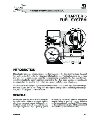
CITATION MUSTANG OPERATING MANUALCHAPTER 5FUEL SYSTEM64MAINFUEL28LBS X 100010INTRODUCTIONThis chapter presents information on the fuel system of the Citation Mustang. Integralfuel tanks in the left and right wings provide fuel storage. The fuel distribution systemprovides fuel to each engine from the corresponding wing tank. The fuel transfer system allows fuel to be transferred from one tank to the other. Crew alerting system (CAS)messages alert the pilot to fuel system emergency and abnormal situations.Information in this chapter is provided for the airframe fuel system upstream of the highpressure engine-driven fuel pump. For description and operation of the engine fuel system, refer to Chapter 7—“Powerplant.”GENERALThe Citation Mustang fuel system includes twointegral wing fuel tanks, an automatic fuel distribution system, and manual fuel transfer capability (Figure 5-1). Each wing tank includesan integral engine feed bay. A primary ejector510OM-00pump and an electrically powered boost pumpprovide fuel to the respective engine. Switcheson the lower pilot tilt panel and CAS messageson the multifunction display (MFD) control andindicate fuel operation and transfer.5-1
5-2PARREAR RYEJECTORPUMPFLAPPERVALVE(FROM)(TO)R ENGINE FUEL SYSTEMFigure 5-1. Fuel Tank FROM)L ENGINE FUEL SYSTEMREAR SPARELECTRICBOOSTPUMPFIREWALLSHUTOFFVALVERAMAIN SPFUELDRAINRPAARD SFORWFLOW-RESTRICTORORIFICEFUELFILLERCAPVENT SCOOPSURGEVENT LINEOVERBOARDVENT LINEARMAIN SPA RD SFORWVENT VALVELEFTSURGETANKFUELPROBELEFT MAINFUEL TANKSURGEVENT LINESCAVENGE EJECTORPUMPSLBS CCAS13PPH700950400AFT DOORP/S HTR LF/W SHUTOFF RFDR FAILSURFACE DE-ICESPD BRK EXTENDF/WOIL SHUTOFFPRESS LOL-RLFUELFLTRCABINALTBP L-RFUELLVLFAILLO L-RT2 HTRRFUELPRES LOW/S O’HEATL L-RFUELBOOSTW/S A/IFAIL L-RLFUELL-RRFUELBOOSTPRES LOFUELLO COLDINOP LENG ITY SUCTIONVENT LINESTRANSFER PRESSURELOW-PRESSURE,HIGH-VOLUME FLOWTO ENGINE FUELSYSTEMFROM ENGINE FUELSYSTEMFUEL INSIDE TANKLEGENDCITATION MUSTANG OPERATING MANUAL510OM-00
CITATION MUSTANG OPERATING MANUALFUEL STORAGEEngine Feed BayDESCRIPTIONThe left and right tanks each have a fuel capacityof 192.5 gallons (728.7 liters) for a total combined fuel capacity per aircraft of 385 gallons(1,457 liters). Refer to Table 5-1 for approximate volumes and weights, or refer to theAirplane Flight Manual (AFM) for current data.The Citation Mustang fuel system does not require the use of anti-icing additives.Table 5-1. FUEL SYSTEM CAPACITYSTANDARD Tanks2,580pounds385gallons1,170kg1,457litersEach wing tank system (left wing and rightwing) includes: Main tank cavity Engine feed bay Venting system Tank filler Sump drain valves Scavenge pumps Fuel probes Flapper valvesAn engine feed bay is an integral part of eachwing tank. It is the lowest point in the fuel system, which is the location for fuel pickup (intake) for the fuel distribution system. Eachfeed bay holds approximately 8 gallons and hasfour vent openings (ensures the bay maintainsfull capacity under all flight conditions).Venting SystemThe venting system consists of a tank, ventlines, flapper, and float-controlled vent valve.A vent surge tank at the most outboard bay ofthe wing fuel tank collects fuel surges from themain tank and also provides a portion of therequired expansion space. The fuel travelsoutboard from the main tank through the surgevent line.During climbs and maneuvers, air trapped inthe forward inboard area of the main tank escapes through the climb vent line to vent intothe surge tank; this allows the main tank areato fill with fuel.A float-controlled vent valve is connected tothe vent surge tank. When the fuel level is fullenough to raise the float, the valve closes,preventing fuel from overflowing into thesurge tank. When the fuel level is low, thevalve opens to provide venting. A flappervalve permits fuel to drain from the surge tankback into the main tank. If the vent surge tankfills, another vent line allows spillage overboard through the NACA scoop (Figure 5-2)under the wing. The vent lines normally allowair to enter or exit through the NACA scoop.The scoop does not require anti-icing.COMPONENTSMain Tank CavityEach main tank cavity (one in each wing, between the forward and rear wing spars) is integral to the wing. Holes in the main spar andribs allow fuel flow through the wing (Figure5-1). Flapper valves, attached to spar and ribholes, allow fuel flow inboard while inhibiting flow outboard.510OM-00Figure 5-2. NACA Scoop Fuel Vent5-3
CITATION MUSTANG OPERATING MANUALTank FillerThe aircraft has one fuel tank filler assemblyon the upper surface of each wing, between themain spar and the aileron (Figure 5-3). Thefiller assembly consists of a flush-type capand a standpipe.When draining sumps, do not turn any tool inthe drain. The drain may lock open, resultingin fuel loss.CONTROLS AND INDICATIONSFuel Quantity Gauging SystemThe fuel quantity gauging system includes asignal conditioner and five fuel quantity probesin each wing. The left and right fuel quantitysignal conditioners gather data from their respective sides and convert the data into the appropriate signals for the G1000 engineindicating crew alerting system (EICAS).The EICAS uses the data for the FUEL quantity display, and for CAS messages to alert thepilot of a low fuel quantity level (in eitherwing) or a failure of the gauging system.Figure 5-3. Fuel Tank FillerSump Drain ValvesSump drain valves (Figure 5-4) are at the lowpoints in each wing where water can collect.In each wing, there is a sump drain in each ofthe following locations: Outboard and inboard of the landinggear (behind the main spar)OPERATIONFuel ServicingFuel servicing includes procedures necessary forfueling, and procedures used to check the fuelfor contamination or condensation. The fuel isserviced through the flush-type cap on the outboard section of either wing (Figure 5-5). In the engine feed bay Between the feed bay and the main spar Between the forward and main spars(forward of the feed bay)Figure 5-5. Fuel Tank ServicingRefuelingFigure 5-4. Sump Drain Valves5-4Refuel in areas that permit the free movement of fire equipment. Follow approvedgrounding procedures for the airplane and510OM-00
CITATION MUSTANG OPERATING MANUALthe fueling equipment. There is one approvedgrounding point under the outboard end ofeach wing (Figure 5-6).COMPONENTSElectric Boost PumpsElectric boost pumps are used for: Engine starting Low fuel supply pressure Fuel transferA 28-VDC boost pump is in each engine feedbay. Either boost pump can be controlled automatically or manually. Circuit protectionfor the boost pumps is in the aft J-box.Figure 5-6. Grounding PointRefuel to the bottom of the standpipe to achievemaximum usable fuel for flight planning. If thefuel tank is filled above the bottom of thestandpipe, there may not be room for expansion, which can result in fuel spillage throughthe fuel vents.Approved fuels and additives for operation ofthe aircraft are listed in the “Limitations” section of the AFM. Use of avgas is not approved.Primary Ejector PumpsThe primary ejector pump is submerged infuel in each engine feed bay (Figure 5-7). Thepump utilizes a small jet of high-pressure“motive flow” fuel (from the respective enginefuel pumps). The fuel passes through a venturi, pulls a larger low-pressure flow of fuelfrom the feed bay, and pumps it back to the engine. Some of the resulting flow also providesmotive flow to the scavenge ejector pumps. Theprimary ejector pump has no moving parts. Itoperates whenever motive flow is available.EJECTOR PUMPOUTPUTMOTIVEFLOWDefuelingDefueling must be performed as a maintenance function.INLETSUCTIONFigure 5-7. Primary Ejector PumpFUEL DISTRIBUTIONDESCRIPTIONScavenge Ejector PumpsThe right side of the wing fuel system is identical to the left side, except for a fuel transfervalve in the right tank and a fuel temperatureprobe in the left tank.A scavenge ejector pump constantly transfers fuel from the forward and outboard areasof each tank to its engine feed bay. This ensures the engine feed bay is full and the primary ejector and electric boost pump aresubmerged in fuel until the wing tank is nearlyempty and the fuel level is drained in the feedbay. Each scavenge ejector pump receiveslow-pressure motive flow from the same side510OM-005-5
CITATION MUSTANG OPERATING MANUALprimary ejector pump or (when operating)the same side electric boost pump.Fuel Transfer ValveThere is a fuel transfer valve in the right engine feed bay. It opens or closes to allow flowbetween left and right wing tanks. It is normallyclosed. The valve is a direct-acting solenoidvalve, controlled by the FUEL TRANSFERselector on the lower instrument tilt panel(Figure 5-8). The valve works with the boostpump on the side from which fuel is beingtransferred. When fuel transfer is commandedby the pilot, the valve opens and the boostpump is energized. Fuel is pumped from the engine feed bay into the opposite engine feedbay through a small opening that limits thetransfer flow. Circuit protection for the transfer valve is provided by the L and R FUELCONTROL circuit breakers in the aft J-box.The fuel transfer valve is not powered when thebattery switch is in the EMER position.commanded closed by the FADEC in the eventthe normal shutdown valve fails. Circuit protection for the shutoff valves are provided bythe L FEED BUS #2 and R FEED BUS #2,through the respective L and R FIREWALLCUTOFF circuit breakers on the aft J-box.Refer to Chapter 8—“Fire Protection” formore information on the firewall shutoff valvesand their operation.Fuel Pressure SwitchesPressure switches are in the engine fuel supply lines adjacent to each engine. The switchesdeactivate at 6.4 psig (maximum) and reactivate when the engine fuel supply pressuredrops below 4.65 psig. When fuel pressuredrops below this limit, the amber FUEL PRESLO L-R message appears.Fuel Flow TransmitterA fuel flow transmitter is on each engine fuelsupply line. The transmitter sends a 0-5 volt analog signal to the G1000 system, which translates the signal to pounds/kilograms per hour.CONTROLS AND INDICATIONSThe pilot controls the fuel system with the Land R FUEL BOOST switches and the FUELTRANSFER selector. Fuel indications are displayed on the MFD in the EICAS window,which is displayed in two columns on the leftside. In the event of MFD failure or revision,the EICAS section is shown in a single-columnformat on whichever displays are in reversionary mode.Figure 5-8. Fuel ControlsFirewall Shutoff ValvesFirewall shutoff valves for each engine are inthe respective aft wing fairing (between thewing and fuselage). In the event of a fire, thevalves shut off fuel flow to the respective engine on pilot command. The valves can be5-6FUEL BOOST SwitchesThe FUEL BOOST switches are on the lowerinstrument tilt panel (Figure 5-8). Each switch(L and R) has three positions: ON, OFF, andNORM.The switches manually control the respectiveboost pumps in the ON and OFF positions. Inthe NORM position, boost pump operation isautomatically controlled.510OM-00
CITATION MUSTANG OPERATING MANUALFUEL TRANSFER SelectorA FUEL TRANSFER selector (Figure 5-8) onthe lower left instrument tilt panel controls the(normally closed) fuel transfer valve.grams. Fuel tank levels are displayed with awhite pointer on a white scale on the fuel display and by green digits just below the scale.In reversionary mode, only the digits are displayed (Figure 5-10).The selector has three positions: L TANK,OFF, and R TANK.The selector opens the fuel transfer valve andenergizes the supply side fuel boost pump,which allows fuel to be pumped to the selected engine feed bay from the opposite engine feed bay.Fuel is transferred at approximately 10 ppm(4.5 kg per minute). Rate varies with engine(s)fuel flow.Figure 5-10. Alternate Fuel Display(EICAS Reversionary Mode)Fuel Quantity IndicationThe aircraft has a passive capacitance-typefuel quantity system. The system consists of: Independent dual-channel digital signalconditioner (in the left aft wing fairing) Five fuel probes in each wing tankTotal aircraft fuel is the sum of the fuel quantities displayed for each tank. This value is displayed below the individual tank quantities ingreen digits. Total fuel quantity is displayedin the same units as the fuel tank levels. Invaliddata is displayed by a red X or white dashes. EICAS displaysFuel quantity is displayed on the G1000 GDU1500 MFD “AUX” page and in the left EICAScolumn of the MFD (Figure 5-9). Quantitycan be displayed in either pounds or kilo-Fuel Temperature IndicationThe fuel temperature probe is inside the leftside engine feed bay. The probe temperatureappears in the fuel display. Fuel tank temperature is displayed as green digits (in C) belowthe fuel flow (see Figure 5-9). If invalid datais received, a red X is displayed. The temperature displayed is invalid if below –70 C(–94 F) or above 99 C (210 F).Fuel Flow IndicationFuel flow is displayed digitally below thetotal fuel display. The digits are green and aredisplayed in pounds per hour (PPH) or kilograms per hour (KGH). Invalid data displaysas a red X.Figure 5-9. Fuel Display in MFD(EICAS Normal Mode)510OM-005-7
CITATION MUSTANG OPERATING MANUALCAS MessagesFUEL LO INOP L-RF/W SHUTOFF L-RThe white FUEL LO INOP L-R message indicates the amber FUEL LVL LO L-R messageis not operational and cannot provide reliableindication of low fuel level.The engine fire-warning and fire-extinguishingsystems allow the crew to detect and suppressfires in the aircraft engine compartments. Whenthe red L–R ENGINE FIRE lights are pressed,the appropriate fuel shutoff valve closes and theamber F/W SHUTOFF L or R message appearson the EICAS (Figure 5-11). This message mayalso appear after engine shutdown if the normal engine shutdown valve fails.CASF/W SHUTOFF L-RFUEL FLTR BP L-RFUEL LVL LO L-RFUEL PRES LO L-RFUEL BOOST LFUEL BOOST RFUEL LO INOPFUEL TRANSFERFigure 5-11. CAS MessagesFUEL FLTR BP L-RIf the fuel filter becomes clogged, the bypassvalve allows unfiltered fuel to enter the engines. Before the bypass valve is opened, a signal is sent to the EICAS system to indicate animpending bypass, which displays the amberFUEL FLTR BP L-R message (Figure 5-11).Refer to the Chapter 7—“Powerplant” formore information.FUEL LVL LO L-RThe amber FUEL LVL LO L-R message indicates that fuel level is low in the indicated wingtank. Each signal conditioner channel sendsan ARINC discrete signal (low fuel level warning) to the EICAS system when the respectivewing usable fuel quantity is less than approximately 170 pounds (25 gallons) (Figure 5-11).5-8In some situations, if the fuel quantity gauging system fails (indicated by a red X on either fuel quantity EICAS display), there maystill be sufficient reliable data for the systemto determine whether or not fuel level isbelow 170 pounds (25 gallons). In this situation, the FUEL LVL LO L-R message isstill useable as a minimum indication of fuellevel (appearing only when fuel level is below170 pounds in either tank). However, if thereis not sufficient reliable data to determine thatfuel level is above or below 170 pounds, theFUEL LO INOP L-R message appears, indicating which tank cannot supply valid data tocontrol the FUEL LVL LO L-R message.FUEL PRES LO L-RWhen the fuel-supply pressure to an enginedrops below the activation point, its pressureswitch closes. The fuel pressure switch completes an electrical circuit, which displays therespective amber FUEL PRES LO L-R message.If the boost switch(es) is in the NORM position,the boost pump(s) automatically energizes.FUEL TRANSFERThe FUEL TRANSFER selector, when in theL TANK or R TANK position, completes anelectrical circuit that automatically energizesthe electric fuel boost pump in the oppositetank and opens the fuel transfer valve. This activates the white FUEL TRANSFER messageand either the L or R FUEL BOOST whiteCAS message, assuming the boost switches arein the NORM position.FUEL BOOST L-RThe FUEL BOOST L-R message is presentanytime the boost pumps are on. The messageis usually white.510OM-00
CITATION MUSTANG OPERATING MANUALThe white FUEL BOOST L-R message appears when the pilot commands the fuel boostpump on (by selecting the FUEL TRANSFERselector to L TANK or R TANK, by selectingeither FUEL BOOST switch to ON, or bypressing a start button).The amber FUEL BOOST L-R message appears when the corresponding fuel boost pumpis energized automatically in response to lowfuel pressure. This is only possible when either FUEL BOOST switch is selected toNORM.ENGINE FIRE LightIn the event of an engine fire, the fire detector in the engine compartment illuminates thered L or R ENGINE FIRE light (Figure 5-12).Pushing the light (which has an integral pushbutton switch) closes the corresponding firewall shutoff valve, which shuts off the fuel flowto the engine and illuminates the amber F/WSHUTOFF L-R message. For details, refer toChapter 8—“Fire Protection.”OPERATIONNormal OperationDuring normal operation of the fuel system,the L and R FUEL BOOST pump switches arein the NORM position. In this position, eachboost pump operates automatically: D u r i n g e n g i n e s t a r t— W h i t e F U E LBOOST L-R message appears. During fuel transfer operation—WhiteFUEL TRANSFER and white FUELBOOST L-R messages appear. When low fuel pressure is sensed in theengine fuel supply line—An amberFUEL PRES LO L-R message appearsfor a moment, followed quickly by anamber FUEL BOOST L-R message. Asthe boost pump quickly increases thefuel pressure, the amber FUEL PRESLO L-R message extinguishes quickly;it may not even be seen by the pilot.If the throttle is OFF, the boost pumps do notenergize automatically in a low fuel pressurecondition, even though the boost pump switchis in the NORM position. When the switch isOFF, the boost pump does not operate. In theON position, the pump operates continuously.Wi t h t h e L a n d R F U E L B O O S T p u m pswitches in the NORM position, pressing anENGINE START button energizes the corresponding fuel boost pump. This moves fuelfrom the wing tank engine feed bay on that sidethrough the firewall shutoff valve to the enginedriven fuel pump on the respective engine.When the engine start terminates, the boostpump is deenergized and the white FUELBOOST L-R message disappears from theCAS window.Figure 5-12. ENGINE FIRE and BOTTLEARMED Lights510OM-00During normal operation, each engine is supplied with fuel from the primary ejector pumpin the engine feed bay of each tank. The electric boost pump (when energized automatically or by pilot command) may augment theoperation of the ejector pump.5-9
CITATION MUSTANG OPERATING MANUALFuel Transfer System OperationUsing the fuel transfer system, fuel is transferred from the wing tank engine feed bay tothe opposite wing tank engine feed bay. Thearrow on the FUEL TRANSFER selectorpoints to the wing tank where transfer fuel isdirected.Rotating the FUEL TRANSFER selector knobfrom the OFF position to the R TANK position:If electrical power fails during fuel transfer operation, the fuel transfer solenoid valve returnsto the closed position, preventing fuel transfer.EMERGENCY/ABNORMALFor specific information on emergency/abnormal procedures, refer to the appropriate abbreviated checklists or the FAA-approved AFM.1. Energizes the left tank electric boostpump. This displays the white FUELBOOST L message if the boost pumpswitch is in the ON or NORM position. (Ifthe boost pump is set to OFF, there is noflow and no FUEL BOOST L message.)2. Energizes the fuel transfer valve open.The white FUEL TRANSFER messageis displayed. The left tank boost pumppressure supplies fuel from the left wingtank engine feed bay through the opentransfer valve and into the right wing tankengine feed bay.Check that the FUEL BOOST L-R message indicates only the correct boost pump is energized. If both boost pumps are energized, fueltransfer does not occur. To deenergize thepump in the nonselected tank, cycle its L orR FUEL BOOST switch to OFF, then ON,then NORM, and leave in NORM position.To verify fuel transfer, monitor the fuel quantity white tape pointers or the digital indicators (see Figure 5-9). Fuel normally transfersto the selected tank at approximately 10 ppm(600 pph). Maximum normal fuel imbalanceis 200 pounds. Maximum emergency fuel imbalance is 600 pounds.To terminate fuel transfer and return the system to normal operation, rotate the fuel transfer selector to OFF. The electric boost pumpdeenergizes (if the FUEL BOOST switch is inthe NORM position), the white FUEL TRANSFER message disappears, and the fuel transfer valve spring-loads closed.5-10510OM-00
citation mustang operating manual 5-2 510om-00 fuel lbs pph c 1500 1000 500 cas oil press lo l cabin alt t2 htr fail r w/s o'heat l w/s a/i fail l fuel pres lo r eng a/i cold l cabin door aft door p/s htr l f/w shutoff r fdr fail surface de-ice spd brk extend 300 700 1040 950 13 400 f/w shutoff l-r fuel fltr bp l-r fuel lvl lo l-r fuel pres lo l-r fuel boost l-r fuel boost l-r fuel lo inop .