Transcription
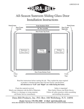
ASRESGD-08All-Season Sunroom Sliding Glass DoorInstallation InstructionsPanel FrameDoor FrameLeft SideFoam Insulator IE241“H” Bar AssemblyPanel FrameDoor FrameRight SideDoor Frame Top TrackStationaryGlass DoorSlidingScreen DoorSlidingGlass DoorDoor Frame Bottom TrackFoamTapeFoamTapeRead the instructions before starting the job. They explain the steps requiredto produce a finished product that will meet factory specifications.All references to “Left” and “Right” are while facing the home.Check the material received.Match your shipment with the Bill of Materials.If there is a shortage or wrong material,call Dealer Service immediately.Safety is important!Wear Safety Glasses and Work Gloves.Follow all safety practices while assemblingand installing this product.Dura-Bilt Products, Inc. P.O. Box 188 Wellsburg, N.Y. 14894Dealer Service 570-596-2000E-Mail info@durabilt.comDURA-BILT RESERVES THE RIGHT TO CHANGE DESIGN AND/OR SPECIFICATIONS WITHOUT NOTICE.
FastenersDescription#8 x 1/2” Self Drilling Screw#10-24 x 1-3/8” Flat Phillips Screw#8 x 1/2” Flat Phillips Sheet Metal Screw#8 x 1/2” Indented Hex Sheet Metal Screw#8 x 1” Slotted Hex Washer Head Sheet Metal ScrewTools NeededDrillLevelHammerCaulk GunUtility KnifeSilicone LubricantTape MeasureChalk LineScrew GunVise GripsHack SawPhillips Screwdriver1/8” & 1/4” Drill Bits1/4” Nut Driver Bit with Magnetic HeadsRubber BumperRound Rubber BumperFor Handle Side of DoorHeader PanelPage 1For Above Sliding Glass DoorFor Wall Heights 90” or Higher1/2” x 3/4” Foam Tape(Between Extrusions)
Extrusions and ComponentsDoor FrameBottom TrackDoor FrameTop TrackDoor FrameLeft & Right Side Tracks“H” Bar Assembly“H” Bar and 1/2” x 3/4”FoamPanel FrameFor sides of Door FrameFoam Insulator IE241(1” High x 3-3/4” Wide)82-3/16” Wall Height Only!Retainer ClipFor Stationary DoorOutside Door HandleStrikerWafer LockForced Entry BracketInside Door HandlePage 2
All-Season Sunroom Sliding Glass Door InstallationAssemble Doorr FramesLay the Frame sections on a flat surfacein their proper positions. Sides of theFrame have the bottom ends stepped tofit the threshold.Note: Insides of Frame have insulationstrips. Fasten top and threshold framesections to side frame sections with two#8 x 1” hex head screws in each corner.Caution! It is critical that frame be madesquare before fastening together. An easycheck is to be sure that corner-to-cornerdiagonal measurements are the same.CaulkCaulk joint where side frames and thresholdmeet. Caulk all around edges of this joint onoutside of both right and left sides.Do not caulk on inside.Locate two Panel Frames and apply (2) two strips of1/2” x 3/4” Foam Tape as shown. The Foam Tape shouldgo from the bottom of the Panel Frame to the top of theDoor Frame Top Track. This will allow room for the FoamInsulator IE241 or the Header Panel. Simply slip the PanelFrames on the Left and Right Side Tracks of the Door Frame.CaulkNote: High side of threshold is placedinside the room, the same way youinstalled the Floor Channel.End view of Panel FrameShowing Foam PlacementBe sure the Panel Frame end with routed holes forFloor Channel are at the bottom of the Frame.Panel Frames do not need to be screwed to the door frame.This unit is now installed in the wall of the roomjust as any other Wall Panel.Install pre-cut Header H-Bar Assembly(s) on the top ofDoor Frame Top Track. This should fit between thePanel Frames and over the Door Frame Top Track.Sliding Door Units for walls 90” or higher call forSolid Header Panels.Insert the pre-cut Header Panel(s)in the H-Bar and attach with #8 x 1/2” Self Drilling Screws.Page 3Side view of Panel Frame showingrouted holes on BottomSide view of the “H” Bar Assembly(Panel Frames removed for clairity)
After the Room Walls are complete, the Glass Door Panels and the Screen Door can be installed in the frame.Weep holes are suggested to drain the two outside channels of the threshold and the Floor Channel. Drill 1/4”weep holes every 10”. Also drill the Floor Channel directly below the hole drilled in threshold.Installing DoorsDoors can be assembled into frames for either Right or Left opening. Right Hand shown in the illustration,Left Hand opposite. View is from outside the room. (Note: the Stationary Door does not have rollers)The Sliding Glass Door is always in the inside track. Stationary Door is in the center track. The Screen Dooris in the outside track. See illustration.After you have determined whether the Sliding Door is going to open from the Left or Right. Install the StationaryDoor in the center track first by inserting the top of the Door into the Door Frame Top Track. If the Sliding Dooris right hand opening, slide the Stationary Door all of the way to the left.Installing The Forced Entry Bracket on the Stationary DoorThe Forced Entry Bracket is designed to keep an intruder from lifting the unit out of the track.Install the Forced Entry Bracket using (2) two #8 x 1/2” Indented Hex Sheet Metal Screws. See Illiustration.Forced Entry BracketView of Fixed Door from OutsideThe Forced Entry Bracket is installed at the topof the Stationary Door#8 x 1/2” Indented HexSheet Metal ScrewPage 4
Installing The Retainer ClipsNext you must install the Retainer Clips inside the room to hold the Stationary Door in place. There are (3)Retainer Clips, (2) two of them are 2” long and the third one is 5-1/2” long. Use (2) two #8 x 1/2 Self DrillingScrews to attach each Retainer Clip. The 2” Retainer Clips are installed 12” down from the top and 12” up fromthe bottom. The 5-1/2” Retainer Clip is installed in the center of the Stationary Door. The notch in the RetainerClips goes over the small lip on the Stationary Door. The Retainer Clips are attached to the Door Frame SideTrack with the #8 x 1/2” Self Drilling Screws. All three Retainer Clips are required to hold the Stationary Doorin place to meet wind load requirements.2” Retainer Clip5-1/2” Retainer Clip12”2” RetainerClipvInside Room5-1/2” Retainer Clipin center of DoorNote: Enlarged viewof the 2” Retainer Clip.The Clip will also coverup the 9/32” hole inthe Door Frame Left orRight Side Tracks, depending on which sidethe Sliding Door opensfrom.This is a view of the Door Frame with the Stationary Doorturned slightly left to show the location of the RetainerClips.12”Page 52” RetainerClip
Installing The Sliding DoorThe Sliding Glass Door has two built-in ball bearing roller glides in the bottom of the door. Before installingthe door into the Door Frame Assembly adjust the ball bearing roller to bring the edge of the roller flush withthe bottom edge of the door.Install the Sliding Door by inserting the top of the Door into the top of the inside track of the Door FrameAssembly, then set the Sliding Door rollers down on top of the roller trackAdjusting the Doors—Adjust the ball bearing rollers by turning the adjusting screw until the panel is squarein the track assembly. Turn the screw driver clockwise to raise the door. Turn counter-clockwise to lower thedoor.Sliding Glass DoorPhillips Screw DriverInstalling The Rubber BumpersThe Round Rubber Bumpers are installed on the handle side of the Sliding Glass Door. The Bumpers fit intothe (2) two 9/32” holes in the Door Frame Left or Right Side Tracks. These Bumpers cushion the door when itis closed.The Large Rubber Bumper fits into the Door Frame Left or Right Side Track and can sit on top of the 5-1/2”Retainer Clip for vertical location. This is a bump for the Sliding Glass Door to hit when it is openedLarge Rubber Bumper in Side TrackRound Rubber Bumper in Side TrackPage 6
Inside Handle InformationThe Inside Handle is ordinarily furnished as shown here, for usewith Right-Hand Door.The inside handle is normally furnished as shown here so that whenthe door is pushed closed it will automatically unlatch, therebypreventing someone from accidentally locking oneself out of thehouse. If the flat spring was placed so that it was against the flatside of the latch, when you shut the door you would be lockedout of the house.The flat spring must look like illustrationfor the Automatic Un-latching to work.TO CHANGE FOR USE WITH LEFT HAND DOOR - lift the flat spring outcarefully, remove the screw from the knob and rotate the knob 180 degrees.Replace the knob, then the screw, then the spring. The Inside handle is now sutablefor use with a left-hand door, as shown here.Note: The knob is again pointing up when in the latched position.Striker InstallationThe Striker will be mounted in the Door Frame Left or Right Side Track (Depending on whether the Dooropens from the left or right) using (3) three #8 x 1/2” flat phillips sheet metal screws.StrikerPage 7Continued on next page.
Striker Installation(Continued)With this Striker; simply place into wider part of jamb allowing positive positioning lug to be inserted in therectangular hole in the Door. Position the Striker approximately where it will be positioned and put a markin the center of the two oblong holes and drill with a 3/32” drill bit then adjust the location of the strike andfasten with (2) two #8 x 1/2” flat phillips sheet metal screws.View of Sliding Glass DoorTurned for clairity.View of Strikein Door jam.PositioningLug1/64” CLEARANCE MAX.Between Striker hook and bottomedge of cut-out in Door.After the Strike has been properly adjusted and tightened, drill a 3/32” hole for the third screw (at top ofstrike). This screw secures the strike for maximum forced entry protection.View of Strikewith all three screws.Page 8
Installing The Sliding Door HandlesInside Handle - Turn knob to latching position as shown. Hold inside handle horizontal and insert latch intocutout in door stile as shown. When latch is thru stile, turn handle to vertical position so that latch appears atrectangular cutout in edge of stile. Press two bosses on the handle into the corresponding holes in stile. Holdhandle in place temporarily.Outside Handle - place in position on outside of stile so that the two screw bosses drop into the correspondingholes in the stile. (Note: If outside handle is equipped with the wafer lock, first insert lock tongue in hole of thelatch). Assemble using (2) two 1-3/8” flat phillips screws thru the inside handle. Push them thru the stile andinto corresponding holes of outside handle. Tighten securely.Installing The Optional Wafer LockThe Wafer Lock Knockout Plug must be knocked out from the back side only! Do not - repeat - do not attemptto punch out the plug from the front face.Back SideUse a hammer and a screw driver orequivalent to knock out the plug fromthe Back Side. Then use a small roundfile or a 1/2” drill bit or both to removeburr.Page 9OutsideHandle
After you knock out the plug, you must clean out the unavoidable burr with a round file or a 1/2” drill bit. Again,be sure to insert the file or drill bit from the back side and work it around several times to remove the burr. Ifthe key lock is still difficult to install, make a few more passes with the file or drill bit.Caution: After installation is complete, check the Sliding Door and make sure that it can not be lifted out, if itcan, strike has not been set correctly.Installing The Screen DoorRoller Adjustment - Follow these steps after screen door is installed to achieve a proper fit.1. Release each roller at the top by turning the adjustment button in the direction shown (less than 1/4 turn isneeded).2. Repeat step above at the bottom, but continue to turn bottom adjustment buttons approximately 1/2 turn orless.AdjustmentButtonPage 10
Installing The Screen Door StrikeStrike FlangeShown up#4 Pan Head ScrewSlotted Areaof Strike ForAdjustment#4 Pan Head ScrewScreen Door StrikeDetermine if the strike flange should be positioned facing up or down (this depends on your door openingdirection). The most favorable position is with the strike flange extending up so that when the screen is closedthe latch lever is moved down to lock the Screen Door.1. Close the Door into the Frame and mark the position to install the Strike.2. If pre-drilled holes already exist in the frame, install the strike through them with screws supplied. If noholes exist, 5/64” holes will have to be drilled to install latch strike.Note: Strike is slotted to give adjustment allowance (up or down).Always adjust the strike so that positive latching occurs before tightening the screws.Page 11
All-Season Sunroom Sliding Glass Door Installation Assemble Door Frames Lay the Frame sections on a fl at surface in their proper positions. Sides of the Frame have the bottom ends stepped to fi t the threshold. Note: Insides of Frame have insulation strips. Fasten top and threshold frame sections to side frame sections with two