Transcription
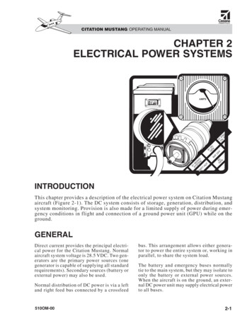
CITATION MUSTANG OPERATING MANUALCHAPTER 2ELECTRICAL POWER SYSTEMSGEN PL#1 ILODC#1 ENGORV MSE TETS1# YHOSTTBATBAFFOACENGINTRODUCTIONThis chapter provides a description of the electrical power system on Citation Mustangaircraft (Figure 2-1). The DC system consists of storage, generation, distribution, andsystem monitoring. Provision is also made for a limited supply of power during emergency conditions in flight and connection of a ground power unit (GPU) while on theground.GENERALDirect current provides the principal electrical power for the Citation Mustang. Normalaircraft system voltage is 28.5 VDC. Two generators are the primary power sources (onegenerator is capable of supplying all standardrequirements). Secondary sources (battery orexternal power) may also be used.Normal distribution of DC power is via a leftand right feed bus connected by a crossfeed510OM-00bus. This arrangement allows either generator to power the entire system or, working inparallel, to share the system load.The battery and emergency buses normallytie to the main system, but they may isolate toonly the battery or external power sources.When the aircraft is on the ground, an external DC power unit may supply electrical powerto all buses.2-1
2-2L DCAMPSVL CBPANEL50 AMPHYD PUMP50 AMPFLAPSL GENVOLTSA#2STARTLBATTPOWERRELAYINTDISCINTERIOR BUSABUSSHUNTL ELE #2R CBPANEL200A MPNORMR AVN#2 SSRR ELE #1R FEED BUS #2R ELE #2R FEED BUS #1R SSR #2 BUS BARLBOOSTSSRVR GENVOLTSSTANDBYBATTERYPACKBATT O’TEMPGEN OFF L–RBATT TEMP FAILAFT JBOX CB L-RAFT JBOX LMT L-RGROUNDBATTERY POWERLEGENDBATTVOLTSBATT TESTOFFSTBY INST100 AMPA/C COMPR DCAMPS100 AMPW/S DEICEAVAFT J-BOXCIRCUIT BREAKERSR AVN GR STARTERGENERATORSTARTRELAYFigure 2-1. Electrical System Schematic200A MPR SSR #1 BUS BARR AVN#1 SSR#1R GENRELAY RMASTERINTERIORSSRR AVIONICS #2R ELE EMERGR AVIONICS #1CROSSFEED BUSL SSR #1 BUS BARL AVNSSRL AVIONICSL ELE EMERGL FEED BUS #2L ELE #1L FEED BUS #1RBOOSTSSRL GENL RELAY#1STARTL AVN EMERGBATTDISCRELAYBATTAMPSSTARTBATTERYBATTT TEMPSENSORRAVN EMERSSR LEFTEMER BUSRELAYBATTERY BUSL100 AMPW/S DEICESTARTRELAYL STARTERGENERATOREXT PWRCONNECTOREXT PWRRELAYCITATION MUSTANG OPERATING MANUAL510OM-00
CITATION MUSTANG OPERATING MANUALDESCRIPTIONThe Mustang electrical system primarily provides 28-VDC power to operate electrical devices throughout the aircraft.A starter-generator is used to start its respective engine, with starting power coming fromthe battery or from a GPU. Additionally, thestarter-generator of a functioning engine (withbattery assistance) can be used to start the opposite side engine.One generator is capable of supplying all standard electrical requirements if a generator fails.DC power is routed from each J-box feed busthrough individual circuit breakers to each ofthe circuit-breaker buses in the cockpit CBpanels. Cockpit circuit breakers control powerto individual systems. Battery power is supplied to a hot battery bus and then through thebattery relay to the crossfeed bus and the leftand right feed buses.Emergency DC power is supplied from thebattery bus through the emergency power relay,to emergency bus circuit breakers on eachcockpit CB panel when the battery switch isin the EMER position. If the battery switch isin the BATT position, generator power is supplied through the battery relay to the hot battery bus to charge the battery and from thecrossfeed bus through the emergency relay tothe emergency power buses.The external power receptacle is underneaththe right engine nacelle.First engine start is performed from the batteryunless using external power. The second enginestart may be powered three different ways: With external power (if the first generator switch is OFF) From the battery (if the first generatorswitch is OFF and external power is notconnected) From the battery with assistance fromthe first generator (ground only) if thefirst generator is online510OM-00Normally, when both engines are operating, thestarter-generator in each engine provides 28VDC power to the main bus system in the tailcone. This bus system and its associated relaysprovide connections and power managementfor the battery and provide for connection toGPUs. This bus system also allows either startergenerator to assist the other during starting andallows the two starter-generators to operate “inparallel” to share the electrical load evenly.From the main bus system in the tail cone, poweris distributed through circuit breakers in thetail cone directly to a few electrical devices inor near the tail cone. More power is routed forward from the main buses through feeder cablesto the cockpit buses. Buses on each side of thecockpit (behind the CB panels) supply powerthrough the cockpit circuit breakers and panelcontrols to most of the aircraft electrical devices.Cockpit indicators monitor electrical systemstatus and performance. Cockpit panel controlsallow the crew to directly manage the generation and distribution of electrical power.Relays, solid state relays (SSRs), circuit breakers, current limiters, and generator controlunits (GCUs) protect the electrical system,and assist the crew in managing the supply andflow of electrical power.COMPONENTSBATTERYA standard lead acid battery provides 24 voltsrated at 28 amp hours. An optional NiCad battery provides 24 volts rated at 28 amp hours.The battery is in the tail cone compartment(Figure 2-2). It has a manual quick-disconnect,and is accessible through the tail cone door.The battery connects to the battery bus. A battery disconnect relay between the battery andits ground provides an electrical disconnectduring certain conditions. A BATTERY disconnect switch (Figure 2-3) is in the cockpiton the left side console panel. This switchopens the battery disconnect relay. Use this2-3
CITATION MUSTANG OPERATING MANUALment that may be powered by the battery bus,from draining the batteries.A battery in good condition supplies power toall buses for a minimum of 10 minutes withmaximum load. If powering only the batteryand emergency buses, battery life should be aminimum of 30 minutes.Figure 2-2. Batteryswitch in case of a battery overheat or stuckstart relay.An INTERIOR DISCONNECT switch is on thepilot side console panel (Figure 2-3). When theswitch is selected to the up position, the master interior relay opens, shutting off all electrical power in the cabin. When the switch isin the NORM position, the master interiorrelay closes, and electrical power flows to thecabin normally (when DC power is availableand the other electrical controls are in the appropriate positions).NOTESTANDBY BATTERYThe optional NiCad battery is susceptible to, and must be protectedfrom, overheat due to excessivecharging or discharging.The standby instrument battery is a 1.2 amphour sealed lead-acid battery. The standbybattery is controlled with the AVIONICSSTBY INST switch.During an external power start cycle, to preventbattery discharge, the battery disconnect relayautomatically disconnects the battery from itsground. A GPU start is not a battery start.Starting the engines with an external powersource is recommended practice to prolongthe life of the batteries and conserve batterypower for times when battery starts must beaccomplished. When it is anticipated the aircraft will be idle for more than 2 days, it isadvisable to disconnect the battery to preventfrequency memory circuits, or other equip-OXYGEN MASKThe standby instrument battery is in theradome on the avionics shelf assembly. Thebattery automatically supplies electrical powerto the standby airspeed, attitude, and altitudeinstruments and the lighting for the whiskeycompass when normal electrical power is notavailable.STARTER-GENERATORSTwo engine-driven DC starter-generators (oneon each engine accessory gearbox) are ONNECTNORMFigure 2-3. Battery Disconnect Switch2-4510OM-00
CITATION MUSTANG OPERATING MANUALprimary source of aircraft electrical powerand supply power to all DC buses. Each generator is air cooled, rated at 29 VDC, and regulated to 28.5 volts.The generators are engine-starting motors thatrevert to generators at the completion of thestart cycle. Each generator system operates independently, but power distributes evenlythrough bus systems that are in parallel exceptduring fault conditions.DC power from the engine-driven generatorsdistributes to two feed buses (see Figure 2-1).Each feed bus connects through a 200-ampcurrent limiter to the crossfeed bus, allowingeach feed bus to parallel the other.During normal operation, the generators shareloads equally (within 10% of the total load) viathe crossfeed bus. Each starter-generator is regulated by its own generator control unit (GCU).Generator power routes from the crossfeed busthrough the battery relay (when it is closed) tothe battery bus. This provides power to chargethe battery, and during generator operation powers the items on the battery bus.Normally (with the battery switch set toBATT), generator power routes from the crossfeed bus through the emergency relay to powerthe cockpit emergency buses and through thebattery relay to power the emergency bus inthe J-box. The battery and emergency relaysare operated with the battery switch.GROUND POWER UNITA GPU can be connected to the aircraft DC system through a receptacle in the fuselage belowthe right engine nacelle (Figure 2-4). Externalpower is routed through the external powerrelay to the battery bus. The battery chargesfrom the GPU, regardless of the battery switchposition.A GPU providing a maximum voltage of 29VDC may be used. The left and right startcontrollers monitor GPU voltage and open theexternal power relay to disconnect the GPU510OM-00Figure 2-4. GPU Receptaclefrom the aircraft if voltage exceeds approximately 32.5 VDC.Before connecting a GPU, ensure that the voltage of the GPU is regulated to 28–29 volts theamperage output between 800 and 1,100 amps.When using external power for prolongedground operation (over 30 minutes), disconnect the battery to preclude overheating the battery. Do not use the battery disconnect switch.CAUTIONSome GPUs do not have reverse-current protection. If the GPU is powe r e d o ff w h i l e c o n n e c t e d t o t h eaircraft, the battery may be rapidlydischarged and/or damaged. Alwaysdisconnect the GPU from the aircraft when not in use.Connecting the external power source energizes the external power relay, which connects the external power source to the batterybus. Setting the battery switch to the BATT position energizes the battery relay, which allowsthe connection of external (or battery) powerfrom the battery bus to the emergency buses,and through the crossfeed bus to the left andright feed buses.When either the left or right generator powerrelay closes, the external power relay deenergizes to remove external power from thebattery bus. This prevents the aircraft generators and the GPU from simultaneously applying power to the aircraft buses.2-5
CITATION MUSTANG OPERATING MANUALCAUTIONIf the battery is charged using theGPU, it must be monitored. Currentfrom most GPUs is not regulated anda battery overheat may occur.DISTRIBUTIONDC power is distributed throughout the aircraftthough several buses (see Figure 2-1) via themain junction box (aft J-box) and cockpitbuses (behind CB panels).Main Junction Box (Aft J-Box)The main junction box (aft J-box) (Figure 2-5)in the tail cone compartment contains: Two feed buses: Left feed bus No. 1 Right feed bus No. 1 Two start buses: Left start bus No. 1 Right start bus No. 1 Two shunt buses: Left shunt bus Right shunt bus Crossfeed bus Battery busFigure 2-5. Aft J-BoxWhen the respective start relay closes, thestart bus is connected to the battery bus, whichsupplies power from the battery or a GPU.Main Feed BusesShunt BusesEach generator (left and right) normally supplies power through its respective generatorrelay to its respective main feed bus (left feedbus No. 1 and right feed bus No. 1). These busesare tied together through the crossfeed bus.The left and right shunt buses connect thestarter-generators to the electrical system. TheGCUs and starter-generators manage the connection of the start buses through the left andright start relay and the left and right generator relay. With the exception of a cross-generator start, normally only one relay at a time(either start relay or generator relay) is closedon each side to connect the correspondingstart bus to the electrical system.Start BusesThe left and right start buses provide power tothe left and right start No. 2 buses and thoseprovide power to the controllers and related systems. In order for the start relay to close, thebattery switch must be in the BATT position.2-6510OM-00
CITATION MUSTANG OPERATING MANUALCrossfeed BusEmergency BusesThe crossfeed bus functions solely as a bus tieconnecting the battery bus, the emergencybuses, and the two main feed buses into oneintegral system.Emergency bus items are listed in Table 2-1.The aircraft has five emergency buses:If the battery switch is selected to BATT, thebattery power relay closes, which connectsthe battery bus to the crossfeed bus. Power extends from the crossfeed bus through 200amp current limiters to each main feed bus.Power also extends from the crossfeed bus tothe cockpit emergency power circuit-breakerbuses and (through the avionics power switch)to the avionics buses.Battery BusThe battery bus is connected directly to the battery. It may receive power from a GPU and during normal operation, receives its power fromeither or both generators. Emergency power circuit-breaker busLeft electrical emergency busRight electrical emergency busLeft avionics emergency busRight avionics emergency bus (withstandby battery)Table 2-1. EMERGENCY BUS ITEMS Standby altimeter COM 1 NAV 1 ADC 1 AHRS 1 Landing gear lights Cabin dump Cockpit floodlights Pilot pitot-static heat Audio panel 1 and 2 Autopilot control panel Standby airspeed indicator Standby attitude indicator PFD 1–Reversion modeCockpit Distribution andCB PanelsThe emergency power circuit-breaker bus is directly connected to the battery bus at all times.Various feed-extension buses, avionics buses,emergency buses, and the interior buses are inthe cockpit.Other buses are powered from either the crossfeed bus, the battery bus, or the standby battery.Feed Extension BusesWith the battery switch in the BATT position,power to the emergency buses is from thecrossfeed bus.From each main feed bus (left feed No. 1 andright feed No. 1) in the tail cone, various extension feed buses distribute power to components through controls and circuit breakersin the cockpit. The main left and right feedextension buses are behind the pilot and copilot CB panels respectively (Figure 2-6). Otherfeed-extension buses are also behind the corresponding CB panels and are powered through25-amp circuit breakers.Avionics BusesAvionics buses (left and right) are poweredfrom the respective main feed buses throughsolid-state relays (SSRs) when the AVN MASTER switch is selected ON. These buses provide power to the aircraft avionics, except theavionics that are on the emergency buses.510OM-00Because the crossfeed bus normally feeds theemergency buses, the pilot must use the battery switch to energize the emergency powerrelay to the EMER position, which switchesall emergency buses from the disabled crossfeed bus to the battery bus.With the battery switch in the EMER position,the following aural warnings are available: Terrain awareness and warning system(TAWS) alert Autopilot disconnect Check altitude Decision height Vertical track Marker beacon2-7
CITATION MUSTANG OPERATING MANUALFigure 2-6. CB PanelsCAUTIONWith the battery switch in the EMERposition, some aural warnings areNOT available, including: Stall warning Landing gear Overspeed Traffic information service (TIS)2-8SYSTEM PROTECTIONGenerator Control UnitsTwo GCUs regulate, parallel, and protect thegenerators. The GCUs are in the tail cone,with one unit dedicated to each starter-generator. Each GCU controls a field and generator relay. Each generator relay connectsthe generator to its feed bus. The GCU permits the generator relay to close when thecockpit generator switch is in GEN and the510OM-00
CITATION MUSTANG OPERATING MANUALgenerator output is within 0.5 volts of normal system voltage (28.5 VDC).When the GCU senses an internal feeder fault(short circuit) or an overvoltage, the respectiveside generator and field relays open. These relays also open when the ENGINE FIRE switchlight is selected.A reverse current (10% of total load) or undervoltage opens only the generator relay, removing the generator from the system but leavingthe field relay closed.cal overload. A list of the protected buses andcomponents is provided below: Left feed bus No. 1—200 amps Right feed bus No. 1—200 amps Air-conditioner compressor—100 amps Windshield heat (left)—100 amps Windshield heat (right)—100 amps Flaps—50 amps Hydraulic powerpack—50 amps HF radio (optional)—50 ampsThe GCU utilizes software and solid-state circuitry to perform the following operations: Control voltage regulation Load sharing Overvoltage/overexcitation protection Automatic generator line contactorcontrol Reverse current protection Overload protection Overspeed protection Open ground protection Open shunt protection Open point of regulation (POR) protection Starter cutoff Field weakening Ground fault protectionSolid-State RelaysSolid-state relays (SSRs) serve as a combination circuit breaker and relay for numerouscomponents. SSRs are individually controlledby cockpit system switches or, in some instances, by remotely mounted printed circuitboards (PCBs).SSRs are installed in either a 25- or 10-amp size;however, they are resistor-adjustable for loweramperage trip points. The following buses andcomponents are SSR-protected and controlled: Left avionics bus Right avionics bus (No. 1) Right avionics bus (No. 2) Left avionics emergency bus Master interior bus Cockpit fanCircuit Breakers and CurrentLimiters Cabin fanParallel feeder cables (between each DC feedbus in the tail cone and the correspondingfeed-extension buses in the cockpit) receiveprotection from circuit breakers. Various othercircuit breakers on the feed buses in the tailcone protect against overload. Left fuel boost pumpCurrent limiters, also known as fuse limiters,are provided to protect against major electri- Right ignitor No. 2510OM-00 Condenser fan Right fuel boost pump Left ignitor No. 1 Right ignitor No. 1 Left ignitor No. 22-9
CITATION MUSTANG OPERATING MANUALRelays and Engine StartingBATTERY SWITCHFor generator-assisted second engine starts,the battery power relay opens to prevent highcurrent flow from the crossfeed bus to thebattery bus and protects the 200-amp currentlimiters. This causes starting current fromthe online generator and battery to flowthrough the two starter relays and battery busto the starter. A blown 200-amp current limiter splits the feed buses, preventing generator paralleling.The battery switch is on the pilot DC POWERsubpanel and has three positions: BATT, OFF,and EMER.Pressing the starter button for GPU starts, firstopens the battery disconnect relay to preventthe battery cycles, then closes the start relay.If GPU voltage is excessive, an overvoltagesensor opens the external power relay andbreaks the circuit to the battery bus. Externalpower disable relays also disconnect the GPUfrom the battery bus whenever a generatorrelay closes, bringing a generator online.CONTROLS ANDINDICATIONSControl of DC power is maintained with abattery switch and two generator switches(Figure 2-7).If the battery switch is in the OFF position, thebattery bus isolates from all other buses inthe system with the exception of the emergency power circuit-breaker bus.When the battery switch is in the BATT position, the battery power relay closes, completing a circuit to the crossfeed bus. The emergencyrelay deenergizes while the battery relay is inthe BATT position and completes a circuit to theemergency buses from the crossfeed bus.In the EMER position, only the emergencypower relay energizes, which connects theemergency buses to the battery bus. Thesebuses receive power from the battery or externalpower. When external power is not applied tothe aircraft and the generators are online, placing the battery switch in EMER or OFF isolatesthe battery from any charging source.BATTERY DISCONNECTSWITCHA guarded battery disconnect switch (see Figure2-3) is above the pilot armrest on the left sideconsole panel. The switch has two positions:BATTERY (disconnect) and NORM. It disconnects the battery and is used only for abnormal operations involving stuck start relay orbattery overtemperature. Activating this switchuses battery power to open the battery disconnect relay on the ground side of the battery.NOTEFigure 2-7. Battery, Generator, andIgnition SwitchesThe battery switch on the DCPOWER subpanel must be in theBATT position for the battery disconnect switch to operate.If the battery ground is open, the battery cannot supply electrical power to the aircraft orreceive a charge from the generators.2-10510OM-00
CITATION MUSTANG OPERATING MANUALCAUTIONDo not use the battery disconnectswitch for an extended time. The battery disconnect relay will continue todraw a small current from the batteryuntil the battery is discharged. Thebattery disconnect relay will thenclose, resulting in a very high chargerate and probable overheat.AVIONICS STANDBYINSTRUMENT SWITCHThe avionics standby instrument switch is onthe AVIONICS pilot switch panel in the cockpit. The switch can be set to the STBY INST,OFF, or BATT TEST position. The switchsupplies power to the right avionics emergency bus.When the standby battery is powering thestandby instruments, the amber light adjacentto the switch illuminates. Selecting BATTT E ST performs a capaci t y chec k on thestandby battery. A successful test is indicatedby a green light adjacent to the switch.ENGINE START BUTTONSTwo engine start buttons (L and R) (see Figure2-7) on the pilot ENGINE START subpanel activate a circuit to close the associated start relayand allow starting current to flow from the battery bus to the starter. A starter disengage (DISENG) button between the starter buttons opensthe start circuit if manual termination of thestart sequence is desired (see Figure 2-7).Pushing the engine start button illuminates awhite light in the starter button as a direct indication that the start relay is closed.INDICATIONSThe DC electrical system is monitored by: Crew alerting system (CAS) messages Engine indicating and crew alerting system (EICAS) display window DC AMPs display BATTERY AMPs display BATTERY VOLTS display Engine start button lightGENERATOR SWITCHESCAS MessagesTwo generator switches (L GEN and R GEN)are on the pilot DC POWER subpanel (seeFigure 2-7). The generator switches have threepositions: L (or R) GEN, OFF, and RESET.BATT O’TEMPSetting the switch to L GEN or R GEN allowsthe GCU to close the generator relay and connects the generator to its feed bus. The ammeter indicates the generator output to thefeed buses.With the switch in the OFF position, the generator relay opens and the ammeter shows nogenerator load to the feed buses.Placing the switch in the spring-loadedRESET position rebuilds field voltage toprovide a means of resetting a generator thathas tripped as a result of a fault condition.510OM-00With the optional NiCad battery installed, abattery overtemperature warning system warnsthe pilot of abnormally high battery temperatures (Figure 2-8). An internal temperatureof 63–70 C (145–156 F) displays an amberBATT O’TEMP message and steady MASTER CAUTION lights.If the temperature reaches 71 C (160 F) a redBATT O’TEMP message displays and theMASTER WARNING lights flash.BATT TEMP FAILAn amber BATT TEMP FAIL message indicates the battery temperature sensor hasfailed (applies to NiCad battery-equippedaircraft only).2-11
CITATION MUSTANG OPERATING MANUAL1040PPH95013 CCASGEN OFF L-RBATT O’TEMPBATT TEMP FAILAFT JBOX CB L-RAFT JBOX LMT L-RVOLTS Display10050-1140013300.8DEST ELVDIFF PSI05-4008K2The left and right generator VOLTS displaysare on the upper-left area of the DC window(Figure 2-9). Each VOLTS display indicatesvoltage at its respective generator. In reversionary mode, only the digits are CASCASNEXRADECHO TOPFigure 2-8. CAS MessagesGEN OFF L-RLoss of a single generator or an open generator relay is indicated by an amber GEN OFFL or R message and triggers steady MASTERCAUTION lights.Dual generator failure is annunciated with ared GEN OFF L-R message and flashing redMASTER WARNING lights.Figure 2-9. Electric Display (Normal)AMPS DisplayAFT JBOX CB L-RAn amber AFT JBOX CB L-R message indicates the left or right start circuit breaker onthe aft J-box has popped. The circuit breakercannot be reset from the cockpit. Maintenanceis required.AFT JBOX LMT L-RAn amber AFT JBOX LMT L-R message indicates failure of a 200-amp current limiter.EICAS Display WindowThe DC window of the EICAS display providesdual generator indications (left and right) forboth voltage (VOLTS) and current (AMPS),and also BATTERY voltage and current.2-12The left and right generator AMPS displays areon the upper-right area of the DC window(Figure 2-9). Each display indicates currentflow from its respective generator to its respective DC feed bus. During normal operation, the indication should be parallel within 10% of total load. Amperage between thestarter-generator and the battery bus is not reflected on the AMPS displays. In reversionary mode, only the digits are displayed.BATTERY–VOLTS DisplayThe BATTERY–VOLTS display is a digitaldisplay on the bottom-center area of the DCwindow. The display indicates voltage on thebattery bus.510OM-00
CITATION MUSTANG OPERATING MANUALBATTERY–AMPS DisplayThe BATTERY–AMPS display is a digital display on the bottom of the DC window (Figure2-9). The display indicates current into orfrom the battery. Positive amperage indicatesbattery charging. Negative amperage indicates battery discharge.OPERATIONPREFLIGHTDuring the interior preflight, place the generator switches to GEN if the intention is abattery start or to the OFF position if external power is desired. Place the battery switchto BATT and verify the voltage display for24 volts minimum (22 volts minimum forNiCad).After checking lights and pitot heat, turn thebattery switch to the OFF position. Duringthe exterior preflight, visually check the battery for signs of deterioration or corrosion. Donot connect external power until completingthese checks.STARTING (FIRST ENGINE)Before starting the engines, recheck the generator switches for proper position and verifybattery voltage. Ensure that the battery switchis in the BATT position.Depressing the L or R ENGINE START button: Closes the respective start relay A green IGN appears on the multifunctiondisplay (MFD) at the upper interturbinetemperature (ITT) scale and indicatescurrent to one or both exciter boxesWithin 10 seconds, combustion should occuras evidenced by rising ITT.As the engine accelerates through 48.6% N 2 : The GCU starter overspeed sensor automatically terminates the start sequence. The start relay opens. The electric boost pump is deenergized. The GEN OFF message disappears fromthe CAS window(GEN switch ON). The green IGN indication extinguishes. N 2 digits change from white to green.STARTING (SECOND ENGINE)For a second engine start on the ground, theoperating generator assists the battery in providing current to the starter. The operatingengine must be at idle rpm.When the remaining start button activates,both start relays close and the white light ineach starter button illuminates.When one generator relay closes and the otherenergizes as a starter, the battery disable relaycauses the battery relay to open the circuit between the crossfeed bus and the battery bus inorder to protect the 200-amp current limiter. Activates the electric fuel boost pumpClosure of the start relay (indicated by illumination of the start button white light) connects battery bus power to the starter forengine rotation.At approximately 8% turbine rpm (N 2 ): FADEC commands fuel flow to the startnozzles Ignition is activated by the full-authority digital engine control (FADEC)510OM-00STARTING (IN FLIGHT)An engine start in flight using the start button is a battery start only. The squat switchdisables generator-assist capability when airborne. Only the associated start relay closesand the boost pump on that side activates.The only difference between an in-flightstart and a ground start with one generatoronline, is that the start relay on the same2-13
CITATION MUSTANG OPERATING MANUALside as the operating generator does not closeand the battery power relay opens. This isolation of the start circuit from the operatinggenerator and buses in flight is through leftsquat switch logic and is required by certification regulations.The protection circuit for the 200-amp current limiter is the same as previously described. Refer to the “Airstart Envelope”graph in “Limitations” of the Airplane FlightManual (AFM).STARTING (ASSISTED BYEXTERNAL POWER UNIT)A GPU can be used for engine starts. Check forvoltage regulation to a maximum of 29 VDCand 800/1,100 amps.When external power starts are planned, thegenerator switches remain in the OFF positionuntil the removal of external power from theaircraft. Otherwise, when the first generatorcomes online, the external power relay opensand the GPU automatically disconnects fromthe battery bus. The second engine start becomes a generator-assist battery start.EMERGENCY/ABNORMALFor specific information on emergency/abnormal procedures, refer to the appropriate abbreviated checklists or the FAA-approved AFM.2-14510O
This chapter provides a description of the electrical power system on Citation Mustang aircraft (Figure 2-1). The DC system consists of storage, generation, distribution, and system monitoring. Provision is also made for a limited supply of power during emer-gency conditions in flight and connection of a ground power unit (GPU) while on the ground.