Transcription
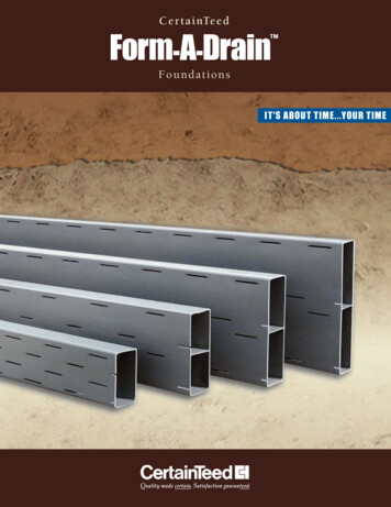
N o r t h A m e r i c an S p e c i a l t y P r o d u c t sI nstal l ati on G ui de3-in-1 SolutionForms Footings Drains Foundations Supports Radon VentingNorth AmericanSpecialty Products
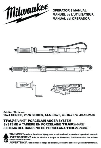
STEP-BY-STEP INSTRUCTIONSRough LayoutBegin with the rough layout of the required number ofstandard 12' lineals, couplings, 90 corners, 45 corners,drain outlets and other necessary accessory parts.CuttingCut lineals to the required length using a hand or powersaw. Do not pre-plan or pre-cut lengths. Simply cut tolength when required and use remaining piece as the nextpiece to be installed. This approach will help minimizewaste by ensuring that numerous short pieces are notleft over. At a corner, cut lineal to required length, insertinto corner and start around the corner with the piecejust cut off. Square cuts help ensure proper alignmentinto couplings, corners and other accessories.LevelingLeveling can begin during or upon completion ofthe assembly of the footing form, using grade stakes(GS018, GS030), steel forming pins or wood stakes.Elevate lineals slightly above the desired elevation levelwhen fastening lineals to stakes or pins; once fasteningis complete, tap the forms back down to the desiredlevel. To fasten grade stakes, place stake against outer(slotted) side of lineal and drill drywall screw throughhole in stake directly into lineal . Wood stakes can besecured using nails. To do so, place the wood stakeagainst the outer side of the lineal and drive nail fromGrade StakeWood Stakeinner (non-slotted) side of lineal into stake; this allowsfor easy removal. If using forming pins, which arepulled after footing is poured, small, fine-thread drywallscrews (instead of coarse thread or bugle screws) arerecommended for fastening. Drywall screws “take” intothe lineals better, and simplify pin removal.TIP: It’s not necessary to back out drywall screws whenpins are pulled. A sharp rap downward and outward onthe pin will snap off the screw head.Forming PinReinforcingHand SawCircular SawAfter leveling, use grade stakes between leveling pointsto reinforce forms. To minimize bowing from the lateralforce of the concrete pour, stake at recommendeddistances of 3' - 5' for 4", 6" and 8" lineals, and at amaximum of 3' for 10" lineals. Place stakes on theouter (slotted) sides of the forms, or use rebar stakes,as required, through holes in coupling/corner pieces.Drive stakes into ground for lateral reinforcement.Reciprocating SawAssemblyI nsert lineals into couplings, corners, or outlets toconstruct each side of the footing form. Slotted side ofthe lineal faces away from the concrete. Accessory itemsare manufactured to ensure a snug fit, so lubricant orsolvent cement is not necessary. Spacer straps may beused to ensure proper footing width. Pin the cornersin place during set-up by driving a rebar stake into theground through the holes in the corners. This will keepthe system aligned and make set-up easier.Spacer StrapsUse of spacer straps — available in 16", 20" and 24"widths — speeds up the setting of forms. Spacer strapscan be removed prior to concrete pour for re-us e.Change in ElevationShould there be a requirement for changes in elevationwithin the foundation plans, FAD is fully adaptablethrough the use of vertical 90 L fittings. The flow ofdrainage remains continuous throughout the system.23
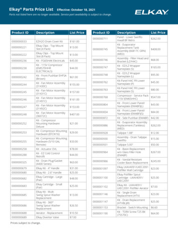
StonePlace stone in the same manner as current practice. In somecases, putting stone in place prior to the concrete pour can holdthe Form-A-Drain system in place.PVC Pipe/Drilled HolesC o rr u g at e d P i p e / O u t l e t sDrainageDrainage outlets can be created in two ways:1. O utlet fittings – Use when the outlets are located at atransition point between lineals.2. O utlet adaptors (AD004) – Use when the outlet mustbe positioned somewhere along the length of thelineal, rather than at a transition point. Install withoutlet positioned at bottom of lineal, by cutting ahole in the lineal using a 3-1/2" standard hole sawwith a pilot bit and insert adaptor.Crossovers connecting inner and outer lineals tofacilitate drainage can be made by connecting outletfittings or adaptors with corrugated pipe.Another option is to use 2", 3", or 4" PVC pipe:Cut the correct size holes in the lineals, and cut theends of the connecting pipe at an angle to keep pipeends from blocking flowinto lineals after pipeis inserted. Drainagedisposal must complywith local codes andpractices. (See “FormA-Drain InspectorGuide” on Page 7for more detailedOutlet Adapterinformation.)Concrete Pour and ScreedingProceed with the concrete pour, filling the footing formwith concrete . Screed off the top of the lineals uponcompletion. The system is left permanently in place toact as the foundation drainage and radon reductionsystem. DO NOT REMOVE FORM-A-DRAIN!Where required, separate filterfabric must be installed. Partiallybackfill outside of footing withappropriate stone, applygeotextile or filter fabric asillustrated (right) and completebackfilling with stone.FORM MethodsAlternativeFAD canaccommodatevarious footingdepths. Proceedas current practiceor code in yourarea dictates forwood or metalforms. Followingare suggestions forinstallation . Formaximum drainage,FAD should beinstalled on bothsides of the footing.Two-Sided FormingRaised/Elevated‑FAD: Low‑Slump‑ConcreteINTERIORWALLEXTERIORFLOOR SLABFOOTINGFORM-A-DRAIN SURROUNDED BY GRAVELINTERIORWALLEXTERIORFLOOR SLABFOOTINGCONCRETE FILL BELOW FORM-A-DRAINCombination FAD with Earth or Trench FormingINTERIORWALLEXTERIORFLOOR SLABTIP: To make sure lineals stay tight against the footingafter the concrete pour and prior to backfilling, drywallscrews can be used as anchors. Simply screw thempartially into the inner (unslotted) surface of the linealsat regular intervals prior to the concrete pour.4OneSidedFormingEither the insideor outside FADlineal may bereplaced by aform for one-sideddrainage. Formcan be wood,metal, plastic,composite, etc.Depending on the footing depth required, raise the top of the linealto meet the top elevation of the footing. For example, if 8" linealsare being used to form a 10" footing, there would have to be 2" ofspace between the bottom of the lineal and the excavated ground(which would be filled in with gravel or concrete). Likewise, 6"lineals may be used to form 8" footings, or 4" lineals may beused to form 6" or 8" footings.FOOTINGFORM-A-DRAINUNDISTURBEDEARTHThis method involves using both lineals and undisturbed earth toform the required footing depth. For example, 4" lineals may beused to form an 8" footing in combination with a trench excavated4" below the bottom of the lineal; there would be a total of 8" ofconcrete — 4" formed by the lineal plus 4" formed by the earth.Similarly, a 10" footing could be formed by combining a 6" linealand 4" trench; a 12" footing by combining a 6" lineal and 6" trenchor an 8" lineal and 4" trench.Perimeter Excavation Only: Higher Slump ConcreteINTERIORWALLFLOOR e contractors prefer this method to save on excavation andgravel cost. A wide (typically 3' to 4') area around the perimeter ofthe floor plan is dug 4" to 6" deeper than the center. Undisturbedearth remains in the center of the excavation. The lineals are theninstalled such that 4" of the footing height is above the undisturbedearth, and 2" to 4" is below. The trench is then filled with gravel,and a 4" layer of gravel is spread over the undisturbed earth toserve as the sub-base for the basement slab.5
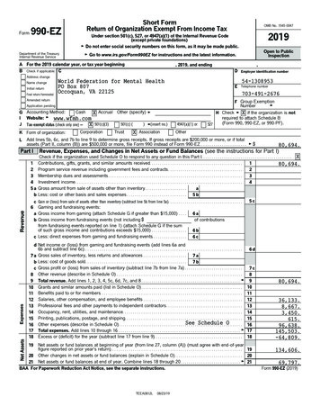
Radon CollectioN & EvacuationINSPECTOR GUIDESub-Slab Perimeter System INSTALLATIONInstall FAD and related system components according to all applicable codes and followinginstructions for conformance with the EPA “Model Standards and Techniques for Control ofRadon in New Residential Buildings.”Form-A-Drain performs multiple purposes:footing form, drainage system and radon reduction system.One of the many advantages of Form-A-Drain is that it canfunction as part of a radon reduction system with onlyone simple modification to the basic installation procedure:installation of one additional outlet in the system for useas the radon gas outlet. This should be placed in positionnear an interior chase where the vertical stack vent piperun is going to be located. The outlet must be installed“upside down” with the round adapter at the top.Types of CrossoversRADON OUTLETOUTLETPRE-WIRED JUNCTIONBOX FOR FAN:(REQUIRED-BOTHPASSIVE & ACTIVE)ROOFINGDUALOUTLETCORNERCROSSOVERSIDING & FASCIAACTIVE SYSTEM:IN LINE FAN FORPOSITIVE VENT5. P lace a continuous layer of polyethylene sheeting or an airgap membrane (Platon ) under the entire slab, overlappingat seams, to serve as a soil-gas retarder.6COUPLINGUse option A or Bto discharge watertoward desireddestination, basedon local practiceand site conditions.FLASHING4. F ill the sub-slab space with a 4" layer of gas-permeable material, such as clean gravel .Contact the United States Environmental ProtectionAgency and/or state and local environmental agen cies for more specific information on radon control. TO SUMPPUMPCROSSOVERACTIVE SYSTEM:SYSTEM FAILUREWARNING DEVICEFLOOR JOISTSOUTLETOption BIt is possible that changes in the sequence ofinspections may be required. Stone should beplaced in the same manner as current practice.Filter fabric should be used in accordance withlocal codes and practices, as required. FAD issubject to CCMC report 13492-R.3" OR 4" PVC PIPECAULK & SEAL ALLBASEMENT SLAB OPENINGSBACKFILLCONTINUOUSPOLYETHYLENEVAPOR BARRIERGRAVELDRAIN BEDWALLBASEMENT SLABFOOTINGGRAVELDRAIN BEDFORM-A-DRAINTEE W/ OPEN ENDTO GRAVEL BEDFor Active Systems1. F ollow step 1 for passive systems . For active systems with a fan,a vertical stack vent pipe within the exterior wall is permitted .2. Follow steps 2 through 8 for passive systems.3. I nstall a ventilation fan in the attic to convert system frompassive to active.Option ADUALOUTLETEXHAUST3. C onnect the vertical stack vent pipe to FAD by running ahorizontal pipe from the radon vent outlet to a PVC tee placedin the gravel. Position the tee directly beneath where thevertical stack vent pipe run is to go. If the tee branch is notlong enough to “stub out” above the basement floor whenpoured, place a small section of PVC pipe in the tee branch.9. P rovide for rough-in wiring in the attic area near the vertical stack vent pipe for later installation of the fan and systemfailure warning device. This step is required! Should subsequenttests indicate an elevated radon level in excess of 4 pCi/L orthe maximum level defined by local code or practices, thepassive system must be converted to an active system.OUTLETPVC TEE2. The vertical stack vent pipe must be either 3" or 4" diameter PVC.8. A ll exposed and visible interior radon vent pipes shall beidentified with at least one label on each floor level. The labelshall read: “Radon Reduction System.”TODAYLIGHTCROSSOVERPVC HORIZONTALPIPE1. P assive venting systems, without a fan, must have the verticalstack vent pipe installed to the interior of the structure,not through the outside wall. This is to ensure sufficienttemper ature differential within the stack to foster anadequate draft.7. I nstall the vertical stack vent pipe run of 3" or 4" PVC pipe,which extends from the tee branch stub out through the roof.Do not use 90 elbows in the vertical stack vent pipe runabove the tee. Properly seal and flash the vent outlet at theroof line.Outlet PositioningNot all types required — refer to local building codes F or Passive Systems6. A fter the basement floor has been completed, seal and caulkany openings in the slab and foundation walls, such as drains,sumps, utility entries, cracks and floor-wall joints to retardsoil-gas entry.Figure 11. L ineals must be installed with the water intake slots facingtoward the gravel, away from the footing .2. D rainage outlet adapters must be installed with the roundadapter positioned at the bottom of the fitting (Figure 1).3. I n situations where only one-sided drainage is accepted,FAD may be used together with wood or other solid forms.Follow installation instructions to form either the insideor outside with lineals, and use solid forms for theopposite side.4. I n installations using crossovers, a minimum of 12 squareinches of crossover drainage area is required. This can beaccomplished with corrugated drain tile attached toForm-A-Drain Outlet Adapters or Outlet Fittings. Crossoverscan also be made using rigid PVC pipe(s) (see Drainage,Page 4). Crossover installations must be level (Figure 2).An alternative to the crossover is to drain the inside systemto a sump pit and the outside system to daylight (drainfield).Properly Positionedfor DrainageProperly Positionedfor RadonFigure 2Crossover DrainageImproperly installedThe outer and innerlineals may also beindividually drained(no crossover).Properly installed — Level5. T he transfer pipe leading to the sump pit or daylight shouldbe 4" in diameter; otherwise, the overall carrying capacity ofthe system will be affected accordingly.6. S hould lineals become damaged or cracked, repair of linealscan be accomplished through one of the following methods: A crack smaller than slot width — do not attempt torepair, this is insignificant. A crack that might restrict drainage flow or allow stoneand dirt to enter — remove small broken piece and coveropen area with duct tape prior to backfill. A crack with large opening — cut out the damagedsection and replace using a small piece of lineal, whichis staked in line using a matching length of lineal. Thiswill not affect the integrity of the drainage system. Coverbroken area by using a coupling with one side cut out.7. The FAD system must be installed level.8. T he FAD system must be backfilled with the appropriategravel or stone in compliance with code requirements.9. A s with any foundation drainage system, roof runoffdownspouts or rain gutters must not be connected intothe system. If required, window wells may be drained intogravel or stone adjacent to FAD, or can be hard-connectedto FAD via use of a downspout adaptor.10. L ocal codes may call for a filter fabric/geotextile screen to beused in conjunction with the foundation drainage system .4. Install a system warning device in an easily accessible location .7
RecEIving,Handling and StoringInspectionStore like this All shipments from a NorthNot like this!American Specialty Productsplant must be inspected as soonas possible after arrival. All NorthAmerican Specialty Products linealproducts are shipped in bulkquantities. Extremely rough handlingen route may cause damage. Begin bymaking an overall inspection of the load. Visual inspection shouldindicate any apparent damage to the product. DO NOT discardany damaged material. Set this material aside and submit claimsfor any damage directly to the trucking company . Make a thoroughcheck to ensure every item on the packing list is received. Anyshortage must be shown on the signed receipt. Each bunk orcarton is marked to indicate the footage, size and type of product,making it easy to check a mixed load. DO NOT throw cartons offthe truck; handle all material carefully at all times.Unloading — Full TruckloadsFAD is designed to withstand normal field conditions, but couldbe damaged by careless handling. Lineals can be easily unloadedin full bunks using mechanical equipment. Unload only one bunkat a time. Unloading in full bunks is the preferred method since itminimizes potential damage.StorageStore lineals on a flat surface and always in a horizontal position. Ifproduct is to be stored for a prolonged period, it is recommendedthat it be left in the original bunk packaging. If product is storedoutside, it must be covered with an opaque material for protectionfrom the sun’s rays, with adequate provision for air circulation.Product must be stored away from excessive heat, because PVCmaterial can be temperature sensitive. Complete bunks of linealsmust be stored in the horizontal or flat direction, with slotted sidedown and with equally spaced supports in at least three placesalong the 12' length. At the job site, individual pieces must beplaced on a flat surface, out of direct sunlight.Exposure to Excessive HeatFittings are provided in cartons that shield the product from directsunlight. Should fittings be subjected to moderate heat, a slightconcave (inward) hourglass effect may occur. This does not affectproduct performance in any way.In the case of both lineals and fittings, it is important to avoidstoring in a high heat environment. Temperatures above 150 -160 Fwill result in permanent distortion.CONSTRUCTION – FOOTING FORM/DRAINAGENote: Refer to local building codes/standards regarding construction regulations pertainingto excavation, footing construction practices and foundation drainage requirements.SYSTEM COMPONENTSAVAILABLE SizeS Part #Lineals4" x 12'LN1246" x 12'LN1268" x 12'LN12810" x "XCPL810"XCPL10Coupling with Hole(molded)6"COUP68"COUP810"COUP1090o Corner(molded)4"CN9046"CN9068"CN90810"CN901045o Corner4"CN4546"CN4568"CN45810"CN45104" Outlet4" OUT448" OUT4810" OUT4104" Double Outlet6" DOF4610" DOF4106" OUT468" DOF48Vertical 90 L4" VL9048" VL90810" VL9010o6" VL906Accessories18" GS018Grade StakeSpacer StrapFor 4", 6", 8"Spacer StrapFor 10"30" GS030width4"width8"4"d x 16"wSS4164"d x 20"wSS4204"d x 24"wSS4248"d x 20"wSS8208"d x 24"wSS824Snap-in Adapter4" fits all AD004 The properties, dimensions and weights of lineals and fittings listed here are subject to normalmanufacturing tolerances. This information is supplied for user reference only and is subject tochange without notice.NEWAsk your distributor for the new CertaForm leave-in-place form – a perfect complementto Form-A-Drain in one-sided drainageapplications.855-624-7473 www.naspecialtyproducts.comNorth AmericanSpecialty ProductsA Westlake CompanyPlease visit us at www.naspecialtyproducts.comNorth American Specialty Products993 Old Eagle School Road, Suite 416Wayne, PA 19087 2014 North American Specialty Products Printed in the U.S.A.Code No. 40-95-04M Rev. 08/14
Follow installation instructions to form either the inside or outside with lineals, and use solid forms for the opposite side. 4. In installations using crossovers, a minimum of 12 square inches of crossover drainage area is required. This can be accomplished with corrugated drain tile attached to Form-A-Drain Outlet Adapters or Outlet Fittings.