Transcription
Drain Separator22-1
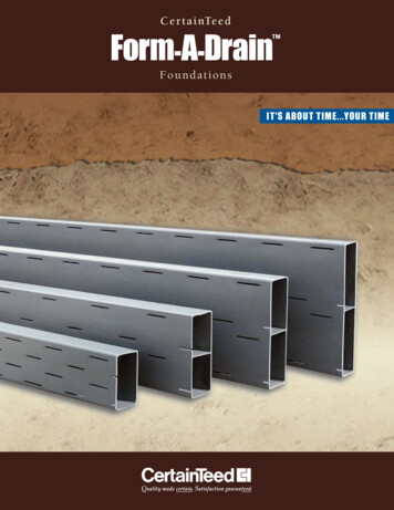
Step 0 Type/Structure/FeaturesPlease refer to this for structure and features of DrainSeparator.Step 1 SelectionDetails are on the product page.Step 2 SizingPlease use Drain Separator of same size with pipe.Step 3 Attention for usagePlease check some guidelines for optimal usage of DrainSeparator such as installation.Reference Experiment onmaterial Drain Separator2-2
Drain Separator2Drain SeparatorWhat is a Drain Separator ?In a steam/air piping system, drain (water) causes problems, such as rust and water hammer. It alsodecreases the dryness and heat quantity content of steam and thermal efficiency in a steamsystem.The DS-1 and DS-2 are separators making use of centrifugal force and impact force to effectivelyseparate drain inside piping. Problems related to existence of drain in the piping systemFailure to properly handle drain in steam piping and air/gas systems results in various problems.Declined thermal efficiencyFormation of scaleDrain in a steam system reduces theeffective heat quantity (latent heat) inaddition to the dryness of steam. In somesituations, drain exposes an excessiveload on a steam trap, making thedischarge capacity insufficient. It alsoforms water film on the heating surface ofthe system, which prevents thermalconduction and reduces the system'sefficiency.Additionally, the water directly carried overIn general, carbon steel pipes for pipingare widely used for steam piping. Whendrain or another liquid contacts them, rustforms. It is quite likely that pressurereducing valves and other control units willmalfunction due to scale, including rust.from a boiler (hot water before evaporation)contains a lot of impurities, and part ofthem form scale that blocks thermalconduction on the heating surface.Drain problems in air/gas systemsPiping or valve corrosion attributable todrain causes a strainer or trap to clog, andcleaning by air blowing sometimesincreases contamination againstexpectations.Outbreak of water hammerWater is higher than steam in density andslows its velocity inside piping because ofits characteristics. However, drain insidesteam piping is carried by steam flowing athigh velocity and may give a strongvibration or load to a valve or controllingunit when drain strikes against it. This iscalled water hammer and causes damageto or wear (erosion) in units.Erosion on main valve of pressure reducing valve2-3www.yoshitake.jp
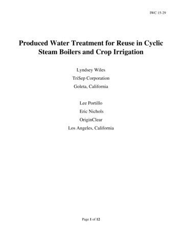
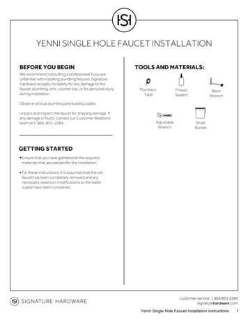
Drain Separator2Drain SeparatorStructure and Principal of Drain SeparatorThere is no movable part. The capacity will not change almost permanently, since the design itself has made thisperfomance possible.Clean and dry fluid(steam/air)Fluid (steam/air)NozzleIt generates cyclonic flowand takes out dry fluid.Cyclone MethodDrain contained insteam/air flow isseparated by centrifuge.Drain gathering around the internalsurface due to centrifugal force.BaffleBy making drain collidewith baffle, only drainwill be led to the outlet.Drain outletto trap Operation· Size of separator can be the same as pipingsize. Since sectional area of inside separatoris larger than piping size, pressure loss isconsidered as zero.· Since no movable parts are used inside, thedrain separator is maintenance-free (exceptthe aging of the gasket).When steam or air flow into the drainseparator, centrifugal force is generated byinternal structure. Drain circles along theinternal surface of the body due to differenceof specific gravity.www.yoshitake.jp2-4
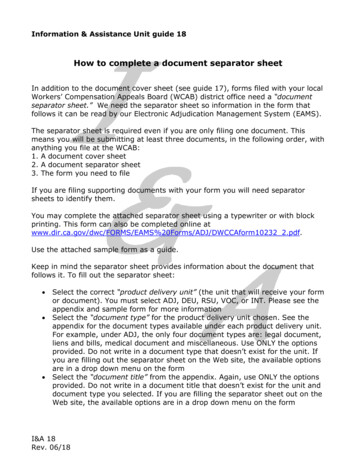
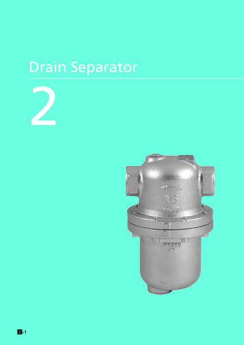
Drain SeparatorDrain Separator2Guidelines for Drain Separator For steam For air Pressure equalizerDrain separatorDrain separatorDraindischarge portAir trapStrainerSteam trapStrainer For air · Connect the drain separator horizontally to pipingDrain separatorwith the drain discharge port down.· Place a trap under the drain discharge port.· Set the top of the trap lower than the drain dischargeport of the drain separator.StrainerAir trap2-5www.yoshitake.jp
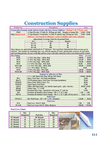
Drain SeparatorReferencematerialFollowing is result of experiment on drain separator. Experiment procedure1. Supply steam with pressure around 0.5 MPa.2. Use V1 and V2 to switch the line with and without DS-1 Drain Separator.3. Reduce steam pressure to 0.02 MPa by GP-2000L pressure reducing valve.4. Measure the steam temperature at the outlet of pressure reducing valve GP-2000L (not the surface temperature ofoutlet of pressure reducing valve) by temperature sensor installed on the outlet side of the pressure reducingvalve.5. V3 is for adjustment of steam flow rate and kept at certain opening.6. Test conditions are as follows:A: V1: open, V2: closed, flow does not go through DS-1B: V1: closed, V2: open, flow goes through DS-17. Test on each condition is continued for 10 minutes, while the temperature is measured every minute. Each test isconducted 2 times continuously switching V1 and V2.SteamPressure reducingvalve for steamTemperature sensorDrain separator Experiment resultTable 1 shows the result under conditions: supplied steam pressure P1 0.46 MPa, reduced pressure P2 0.02 MPaand steam flow rate 150 kg/h.Table 1. Change of temperature of the outlet of pressure reducing valveNo.Test conditionTemperature of outlet ofPRV after 10 mins1A (did not go through DS-1)104.2 C2B (went through DS-1)* 123.7 C3A (did not go through DS-1)105.0 C4B (went through DS-1)* 124.5 C* Saturated steam temperature at 0.02 MPa is 104.8 CThis result implies that under this condition, steam becomes superheated steam when its pressure is reduced aftergoing through separator (DS-1).www.yoshitake.jp2-62Drain SeparatorExperiment on Drain Separator
Drain SeparatorDrain Separator2Experiment on Drain Separator ConsiderationDryness indicates amount of water (condensate/drain) contained in steam. So dryness of complete steam isdescribed as 100%, and if the entire amount is drain, the dryness is 0%.In other words, dryness mentions how many percent of latent heat the steam contains.Thus, here we will consider improvement of dryness by converting heat quantity into temperature.Under the conditions (supplied steam pressure P1 0.46 MPa is reduced to 0.02 MPa), theoretical temperature ofsteam by dryness is as on the table below:Table 2. Theoretical value of steam temperature0.46 MPa steamDryness(%)Sensible heat(KJ)Latent heat(KJ)0.02 MPa steamTotal heat(KJ)Surplus heatamount afterTotal required heat Saturation pointpressure(KJ)( C)reduction (KJ)Theoreticaltemperaturerise ( C)10065820942752(1) 6582031268952.5107.32684104.8(2) 34Theoreticalsteam temp.( C)(3) 138.8* Specific heat of steam is assumed as 0.5 C/KJ.* Heat amount is shown in value contained by 1 kg of steam, figures after decimal point omitted.Assuming dryness is 100%, when steam with supplied pressure P1 0.46 MPa is reduced to 0.02 MPa, thedifference of total amount of heat becomes surplus:2752 (KJ) – 2684 (KJ) 68 (KJ) (1) in Table 2Since the specific heat of steam is around 0.5 C/KJ, we can convert this surplus heat into temperature and calculatetheoretical temperature rise:68 (KJ) x 0.5 ( C/KJ) 34 ( C) (2) in Table 2Therefore, theoretical temperature of steam after pressure reduction is104.8 ( C) (saturated) 34 ( C) 138.8 ( C) (3) in Table 2This is temperature of superheated steam.Considering above, we can compare the test result and theoretical value in Table 2 as follows:(I) Under condition A (steam does not go through Drain Separator), temperature after pressure reduction is 104-105 C, so it is saturated steam at 0.02 MPa. This means dryness of steam supplied to pressure reducing valvewithout going through DS-1 is 97% or lower (we cannot specify actual dryness). * If it is 97%, 104.8 ( C) {5 (KJ)x 0.5 ( C/KJ) } 107.3 ( C) 104-105 C(II) Under condition B (steam goes through Drain Separator), temperature after pressure reduction is 123-124 C, so itis superheated by 18-19 C compared to saturation temperature at 0.02 MPa. * If it is 98%, 104.8 ( C) {26 (KJ)x 0.5 ( C/KJ) } 117.8 ( C) 123-124 CThis means dryness of steam supplied to pressure reducing valve after going through DS-1 is 98% or higher. (Thissystem is not insulated and subject to effect of heat release, so it is assumed that dryness is actually around99%.)Thus, it can be concluded that steam with dryness 97% is improved in quality into dryness 99% by going throughDS-1.2-7www.yoshitake.jp
Drain Separator NoteThis is a test result only under conditions mentioned above. Especially, please be advised that dryness of steamcannot be maintained for long, and it will drop soon due to heat release affected by factors such as distance fromDS-1.Besides, this experiment is just an example to check effect of DS-1 and it is not to guarantee its performance.Experiment at TSCwww.yoshitake.jp22Drain SeparatorReferencematerial-8
Drain SeparatorDrain Separator2DS-1,2Drain (condensate) in steam and air pipingcauses a decline in thermal efficiency, waterhammer, corrosion of devices, valves, and pipes,and many other problems.The DS-1 and DS-2 drain separators are capableof efficiently separating condensate from steamand air with the aid of centrifugal forcegenerated from the configuration of thepassage. In normal condition, use a separator ofthe same size as piping for both steam andcompressed air systems.DS-1 Features1. High efficient drain separation due to cyclone type.2. Extremely low pressure loss.3. Trouble-free by minimizing the number of moving parts. SpecificationsModelApplicationMaximum pressureMaximum 1DS-2Steam, Air2.0 MPa (1.0 MPa for air)220 CDuctile cast ironCast ironDuctile cast ironJIS Rc screwedJIS 10K/20K FF flanged Dimensions (mm) and Weights (kg)ModelDS-1DS-2Nominal dRc 1/2Rc 3/4Rc 1Rc 1-1/4Rc 1-1/2Rc 2 L150150150190190219174 (178)204 (208)204 (208)222 (226)242 (246)246 (250)288 (292)335 (343)390 Rc 3/4Rc 3/4Rc 3/4Rc 1Rc 1Rc 1Rc 3/4Rc 3/4Rc 3/4Rc 1Rc 1Rc 1Rc 1Rc 1-1/4Rc 1-1/4Weight7.17.17.312.512.520.58.5 (8.7)9.6 (9.8)10.1 (10.5)15.6 (16.0)16.3 (16.7)24.7 (24.9)40.0 (40)54.0 (56.0)96.0 (100.0) The above values in parentheses are the dimensions and weights of JIS 20K FF flanged.2-9www.yoshitake.jpDS-2
DS-1, 22Rc 3/8DS-1Drain SeparatorRc 3/8DS-2 Selecting a Nominal SizeKeep the instruction described below in mind to enablethe drain separator to operate most effectively and meetworking conditions to the fullest extent possible. Selecting a drain separator nominal sizeSelect the same nominal size as that of piping (nominalsize of piping nominal size of drain separator). Using adrain separator of a smaller nominal size may increasepressure loss, resulting in failure to keep the specifiedpressure at the outlet of a unit.Table 1: Working flow velocityApplicationSteamAirFlow velocity30 m/sec or less15 m/sec or less* Keep the fluid below the specified flow velocity.* A higher flow velocity may cause drain separation to fail. Guidelines for Drain Separator1. Check the following direction of the fluid and the inletand outlet directions of the drain separator in advance,and properly install it.2. When connecting it to piping, securely support theproduct and the piping with a lifting device.3. When installing the product, secure the space of thedimension H3 shown in the figure below, which isrequired for maintenance and inspections.* When using model DS-1, 2 for steam application, it isrecommended to replace the gasket after 2 years as aguide.Table 2: Maintenance required dimensionModelwww.yoshitake.jpNominal size2-10
Drain Separator 2 Drain Separator Structure and Principal of Drain Separator Fluid (steam/air) Clean and dry uid (steam/air) It generates cyclonic ow and takes out dry uid. Drain gathering around the internal surface due to centrifugal force. By making drain collide with baf e, only drain will be led to the outlet. to trap Drain contained in