Transcription
2018ResidentialWiring Guide13th Edition
This guide is designed to help you install residential wiring safelyand in accordance to the standards set by the 13th edition of theManitoba Electrical Code 2018.Every effort has been made to ensure the accuracy of theinformation in this booklet. However, in the event of a discrepancybetween this booklet and the governing Manitoba Electrical Code,the Manitoba Electrical Code shall take precedence.Remember, the Manitoba Electrical Code is constantly beingupdated. Be sure to familiarize yourself with the latest coderequirements before you begin wiring.The Manitoba Electrical Code has been established to protect youand your family from shock and fire hazards that may occur whenwiring is improperly done, or if sub-standard materials are used.Don’t take shortcuts.Violating the code puts lives at risk.You can view or print a copy of this guide on our website at hydro.mb.ca.If you have any questions or would like to make arrangements for aninspection, call 204-480-5900 in Winnipeg or 1-888-624-9376.Users of the Residential Wiring Guide (the “Guide”) are responsible to ensure that their electrical wiring is installed in compliance with thecurrent Manitoba Electrical Code and any other applicable laws, regulations, by-laws and codes. Users rely on the information containedin this Guide at their sole risk and are strongly encouraged to seek the advice of a qualified electrician regarding their electrical wiringinstallations. Manitoba Hydro shall not be liable for any injury, loss or damage caused to any person or property by reason of defectsin any electrical wiring or in any improper installation of electrical wiring resulting from the use of this Guide.1
ResidentialWiring GuideIntroductionAnyone who plans to carry out electricalinstallation work is required by lawto obtain an electrical wiring permit.Permits for Winnipeg are issued by theCity of Winnipeg Planning, Property &Development Department, Development& Inspections Division, 4th Floor, 65 GarryStreet, Winnipeg, Manitoba, R3C 4K4.“Do It Yourself ” is a popular theme forhome and cottage owners these days.Manitobans are choosing to build newhomes, additions and cottages, so it isonly natural that installing electrical wiringhas joined the realm of do-it-yourselfprojects. However, electrical wiringmust be installed safely and correctly inaccordance with the current ManitobaElectrical Code.If the building to be wired is located outsideWinnipeg, you must apply for your permitonline at hydro.mb.caManitoba Hydro has published thisguide to help you install your own wiringsafely and in such a way that the finishedinstallation will comply with the ManitobaElectrical Code. Manitoba Hydro stronglyrecommends that wiring be done bylicensed electricians. However, if youwould like to do your own wiring, andfeel capable, this manual will help.Manitoba Hydro servicePower is distributed to residences andcottages through overhead wires orunderground cables. The service suppliedis a three-wire service, which consistsof two live conductors and one neutralconductor. Three-wire service provides120-volt, 120/240 volt and 240-voltcapabilities.If you have any doubts about wiring aparticular area of your home or cottage,do not proceed until you have consultedwith an electrician and confirmed thecorrect way to proceed.2
CHAPTER I – THE WIRING PLANGeneral. 5Kitchen. 5Bathrooms and washrooms. 7Laundry areas. 7Garage/carport. 7Outdoor receptacles. 7Basement area. 7Other areas of the dwelling. 7Balcony or porch. 8Central vacuum system. 8Smoke alarms. 8Carbon monoxide alarms. 8Heat sensors in storage garages. 8Submersible pumps installed in lakes, rivers and streams. 8Service size. 9Obtaining an electrical permit. 9CHAPTER II – MATERIALSExplanation of material and terms. 11CHAPTER III – TOOLS REQUIREDEquipment safety. 14CHAPTER IV – WIRINGService conduit. 16Meter sockets. 17Served from underground supply. 17Service box and distribution panel. 19Service grounding. 19CHAPTER V – CIRCUITSRunning cables. 20Mounting boxes. 21Receptacles. 22Colour coding of conductors. 25CHAPTER VI – WIRING TIPSAttaching conductors to screw type terminals. 26Use of wire connectors. 26Supporting cables. 26Metal protectors. 26CHAPTER VII – INSPECTIONSRough-in inspection. 27Final inspection. 27CHAPTER VIII – WIRING AN EXISTING BUILDINGService size. 28Upgrading existing branch circuits. 28Safety. 293
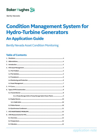
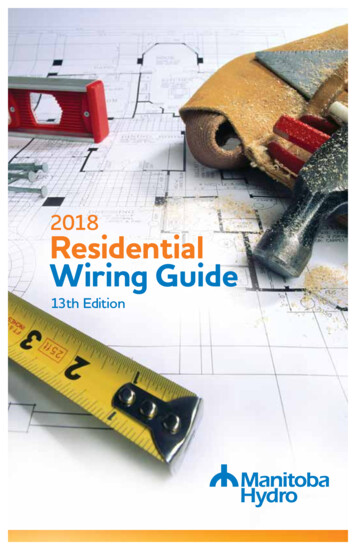
4BEDROOM 3WASHROOM3W CIRCUIT TO PANEL2W CIRCUIT TO PANELCCTS 12 & 16 AFCI & GFCI PROTECTEDCCT.1 - 1 POLE 20A TYPE 5-20R GFCI PROTECTEDCCT.2 - 1 POLE 20A TYPE 5-20RLEGENDBEDROOM 2GFCIPROTECTEDBEDROOM 1Figure 1 – Floor planW.P.GFCIPROTECTEDUTILITYROOMLIVING ROOMKITCHENGFCI PROTECTED20A - 5 - 20R(T-SLOT) RECEPTACLEDRIVEWAYW.P.GFCIPROTECTEDCHAPTER I – THE WIRING PLANIn this chapter, we’ll detail what information should be marked on a floor plan to developa wiring system, the size of service required, and how to obtain an electrical permit.Figure 1 shows an example of a floor plan on which a wiring system has been developed.
Generalcontrolled by a single switch locatedat the head of the stairs andprovisions for three-way switchingmust be installed.a) All 15 amp (5-15R) and 20amp (5-20R) receptacles shall betamper-resistant and shall be marked.Receptacles that are dedicated forstationary appliances where thereceptacle is inaccessible or for thoselocated 2 metres above the floor orfinished grade are not required to betamper-resistant.e) There shall be no more than 12outlets (lights and receptacles) onany two-wire branch circuit.KitchenIn the kitchen you’ll require circuits andoutlets for the refrigerator, range, counterspace, built-in microwave oven, and lighting.b) Each branch circuit supplying 15amp (5-15R) and 20 amp (5-20R)receptacles shall be protected by acombination-type Arc Fault CircuitInterrupter (AFCI).a) Refrigerator – A separate receptacle,supplied from a separate circuit, forthe exclusive use of the refrigeratormust be installed.Receptacles installed for the kitchenfridge, kitchen counters, kitchenisland, kitchen peninsular and thoseinstalled within one metre of thebathroom or washroom sink will beexempt from the AFCI requirements.A single receptacle for a sump pumpwill also be AFCI exempt whenlabelled to identify it as the sumppump receptacle.There is one exception to thisrequirement: you may connect arecessed clock receptacle to therefrigerator circuit.Mark the location of the refrigeratorreceptacle on the floor plan andindicate that the circuit goes directlyto the distribution panel.In lieu of an AFCI breaker, an AFCIoutlet branch circuit-type interruptermay be used when it is installed asthe first outlet on the circuit and thewiring method from the overcurrentdevice to the first outlet is a metalraceway, armoured cable or nonmetallic conduit or tubing.b) Range – A separate receptacle mustbe located in approximately thecentre of the wall space where therange is located (130 mm maximumfrom the floor and oriented as shownin Figure 2).Mark the location of the receptacleon the floor plan and indicate thatthe circuit goes directly to thedistribution panel.Some circuits will require both AFCIand Ground Fault Circuit Interrupter(GFCI) protection.Where a gas (natural gas or propane)piping system or a natural gasconnection outlet has been providedfor a free-standing, all natural gasrange, one receptacle must belocated behind the intended naturalgas range location, not more than130 mm from the floor and as midpoint as possible.c) A luminaire controlled by a wall switchshall be provided for each room.d) Each stairway with four or more risersmust have a luminaire that is controlledby three-way wall switches locatedat the head and foot of the stairs.If the basement is not finished, thenthe luminaire is permitted to be5
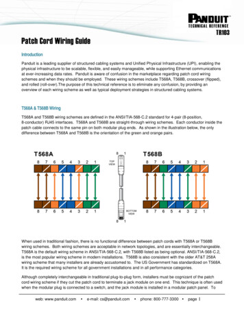
c) Usable counter space – At least tworeceptacles (15 A - CSA configuration5-15R, or 20 A - CSA configuration5-20R) shall be provided for kitchencounters. These receptacles must beinstalled so that no usable counterspace, as measured along the wallline, is farther than 900 mm froma receptacle (excluding the areadirectly behind the kitchen sink).If you are installing a peninsula or afixed island in your kitchen you willhave to install a receptacle for eitheror both of these areas if they have acontinuous dimension greater than300 x 600 mm. Receptacles locatedwithin 1.5 metres of the sink must beprotected with a GFCI of the Class Atype. This will require that they be ofthe 20 A, 5-20R type, connected to a20 A circuit breaker or fuse and wiredwith No.12 AWG copper wire.If more than two receptacles arerequired, they can be installed as eithera three-wire 15 A circuit or two-wire20 A circuit. This three-wire splitreceptacle circuit consists of a duplexreceptacle wired in such a mannerto provide 15 A of power from eachoutlet. No more than two receptacles,of either type, shall be permitted to beconnected to any one circuit.Mark the location of the receptaclesand their circuitry on the floor plan.Indicate the two-wire or threewire circuits going directly to thedistribution panel.Figure 2 – Range receptacle installationLEFT VERTICAL EDGE OFWALL SPACE INTENDEDFOR RANGERECEPTACLE CSACONFIGURATION14-50RRECEPTACLE MUST BEORIENTED SO THATU-GROUND SLOT ISON EITHER SIDE130 mmMAXIMUMFLOOR LINEAPPROXIMATELY ONE-HALF OFWALL SPACE INTENDED FORRANGE6
d) Built-in microwave oven – If you planto install a built-in microwave in anenclosure, a receptacle supplied froma separate circuit must be installed.This circuit must not be considered asforming part of other kitchen circuits.On the floor plan, mark the locationof the receptacle and its circuit, andindicate that the circuit goes directlyto the panel.within one metre of each cord-connectedgarage door opener. A dedicated circuitis required for a garage or carport.The garage lighting may be added tothis circuit.Outdoor receptaclesYou must have at least one receptacleinstalled for the driveway area along withan additional outlet accessible from gradelevel on the outside wall of a cottage orhome for use with appliances designedto be used outdoors. Each of thesereceptacles is required to be connectedto its own separate branch circuit.e) Cord-connected range hood orcombination microwave oven/rangehood unit – The receptacle requiredfor this appliance is allowed to beinstalled in a cupboard or cabinet.All outdoor receptacles located within2.5 metres of ground or grade level mustbe protected by a GFCI.f) Additional outlets – Outlets forgeneral lighting, task lighting, finishedkitchen walls, and exhaust fans shouldbe marked on the wiring plan. Theircircuitry can be connected with thegeneral circuitry in the structure.All installed 15 and 20 amp receptaclesexposed to the weather will requirecoverplates marked “Extra Duty”.Mark the location of each receptacle onthe floor plan and indicate that the circuitgoes directly to the distribution panel.Bathrooms and washroomsA receptacle must be installed at eachhand wash basin, and the receptaclemust be protected by a GFCI. Mark thelocations of all the bathroom outlets(lights, fans, and hand basin receptacles) onthe floor plan.Basement areaEven if you do not plan to finish yourbasement at this time, you must install atleast one receptacle in the basement area.This receptacle may be on a circuit thatsupplies other general use receptacles.Laundry areasIf you plan to include a laundry area inyour home, you will require a receptacleserved by a separate two-wire circuitfor a washing machine and a separatereceptacle supplied from a separatethree-wire circuit for an electric dryeror in the case of a natural gas dryer,a separate, two-wire circuit.Other areas of the dwellingGeneral-use receptacles in bedrooms,living rooms, and other areas must belocated so that no usable wall space isfarther than 1.8 metres from a receptacle.When measuring the spacing betweenreceptacles, do not include:Mark the location of the receptacles onthe floor plan and indicate the circuitsgoing directly to the distribution panel. Garage/carportAt least one duplex receptacle is requiredfor each vehicle space in a garage orcarport. Receptacles are also required7doorways;areas occupied by a fully opened door;windows that extend to the floor;fireplaces;other permanent installations thatlimit the use of the wall space.
No point in a hallway of a home orcottage is to be farther than 4.5 metresfrom a receptacle, without going througha doorway. For example, an outlet in abedroom cannot be counted as a hallwayreceptacle.Carbon monoxide alarmsA carbon monoxide alarm is required inevery home that contains a fuel-burningappliance or an attached garage. Alarmsare to be installed either inside eachbedroom or, if outside, within 5 metresof each bedroom door.All general use outlets must be shownon the plan and the circuitry should bemarked to indicate that no more than12 outlets are connected to one twowire circuit.They must operate at 120 volts and besupplied by an unswitched lighting branchcircuit or a combination lighting andreceptacle branch circuit.Balcony or porchCarbon monoxide alarms shall beinterconnected so that the operation ofany one device will activate all the otheralarms. Combination smoke and carbonmonoxide alarms may be used as theycan reduce the number of units to bemaintained.In an area such as a balcony or porch,you must install at least one receptacle.Central vacuum systemIf you plan to install a central vacuumsystem, it must be supplied by a receptacleon a separate circuit.NOTE: Carbon monoxide alarms are to beinstalled according to the manufacturer’sinstructions.Smoke alarmsSmoke alarms with battery backupmust be installed on all floors, includingbasements. If the home is a split-level or abi-level and it is 900 mm above or belowthe adjacent level, it must be counted asa different floor and must have its ownalarm. A smoke alarm with battery backupmust be installed in each bedroom andthere must be one in the hallway thatserves the bedroom(s).Heat sensors in storage garagesA fixed-temperature heat sensor shallbe installed in an attached garage andis to be installed on the ceiling of thegarage or bottom of a ceiling joist ofgarages with no ceiling. Permanent wiringto an electrical circuit must ensure thatactivation of the sensor will cause allalarms within the home to sound.They must operate at 120 volts and besupplied by an unswitched lighting branchcircuit or a combination lighting andreceptacle branch circuit.Submersible pumps installed inlakes, rivers and streamsIf you plan to install a submersible pumpin a lake, river or stream, the voltagesupplying the pump must not exceed150 volts to ground. The branch circuitthat supplies the submersible pump mustbe provided with GFI protection with a highenough setting to allow normal operationof the pump, but must limit the groundfault current to less than 10 mA for aperiod not exceeding 2.7 seconds.Smoke alarms shall be interconnected sothat the operation of any one device willactivate all the other alarms. Combinationsmoke and carbon monoxide alarms maybe used as they can reduce the numberof units to be maintained.NOTE: Smoke alarms must be installedaccording to the manufacturer’sinstructions.8
Obtaining an electrical permitOnly heat trace cable having a metalbraid or sheath is allowed to be installedon water lines to prevent freezing. Thismetal braid or sheath must be bondedto ground.As mentioned in the introduction, youmust obtain an electrical permit beforestarting any wiring.You must apply online for an electricalpermit at hydro.mb.ca.The heat trace circuit must be protectedby a GFI with a high enough setting toallow the normal operation of the heater.The setting for this GFI is from 25 mAto 30 mA. The GFI required for both ofthese types of installations is differentfrom the normal GFCI for your bathroomor outside receptacles, which has a settingof between 4 mA to 6 mA.Manitoba Hydro will review yourapplication, calculate fees and issue anelectrical permit. The fees are assessedin accordance with the current ManitobaHydro schedule of electrical permit fees.If you plan to build a new structure,your electrician must contact your localManitoba Hydro Customer Service Centreto determine where the electrical servicewill be attached to the building. (See“Service conduit” Chapter IV.)Service sizeManitoba Hydro recommends a minimumservice size of 100 amps, complete with a24-circuit distribution panel. A 100-ampservice should be capable of supplying upto 10 kW of electric heating, in additionto the normal loads in a residence orsummer cottage.If you are installing more than 10 kWof electric heating, a service larger than100 amps is required. The service sizeshould be based on calculated kilowattdemand, which takes into considerationthe floor area, appliances, electric heating,pumps, motors, and other loads that maybe installed, such as hot tubs and saunas.An electrical service permit can only beissued to a licensed electrician and theservice must be installed by the electrician.Consult with your electrician to ensurethe service size is appropriate for yourcurrent and future needs.9
CHAPTER II – MATERIALSThe Manitoba Electrical Code requires that all wiring materials be approved by anaccredited certification organization, such as those below. Failure to use approvedmaterials will result in the inspector refusing to accept the installation. Manitoba Hydrowill not connect the service until the inspector accepts the installation.Electrical inspection authorities across Canada will accept electrical equipment withcertification markings other than the CSA logo. Here are some logos that denoteapproved electrical and gas equipment:1) Canadian Standards Association2) Underwriters Laboratories Inc.(The UL logo without the small “c” is not acceptablefor use in Manitoba.)3) Warnock Hersey4) Electrical Testing Laboratory(The ETL logo without the small “c” is notacceptable for use in Manitoba.)5) Canadian Gas Association6) Underwriters Laboratories Canada Inc.For further information, contact your local electrical inspection authority or the Officeof the Fire Commissioner, Inspection and Technical Services Manitoba.10
Explanation of materials and termsAmerican Wire Gauge Number:Common wire sizes:The standard measurement for thediameter of a wire is the AmericanWire Gauge (AWG) number. It is ameasurement of the wire only, anddoes not include the insulation coveringthe wire.There are four basic wire sizes that arecommonly used for wiring the circuits of ahome or cottage: No. 14, No. 12, No. 10,and No. 8. No. 14 AWG is used for 15 ampcircuits that supply loads such asreceptacles, switches, and lights. No. 12 AWG is used for 20 ampcircuits that supply loads such askitchen counter receptacles. No. 10 AWG is used for 30 ampcircuits that supply loads such aselectric clothes dryers. No. 8 AWG is used for 40 ampcircuits that supply loads such aselectric ranges.Single conductors:Single conductors must be covered byinsulation, except when the conductoris for a service neutral or for groundingpurposes, in which case it may be bare.Single conductor cables are normallyinstalled in service raceways.Multi-conductor cables:Multi-conductor cables are cablesconsisting of two or more conductors.There are two types of non-metallic (NM)sheath cable commonly used for wiringa home or cottage. The first is NMD90,which is used indoors for the bulk ofyour circuit wiring. The second is NMWU,which is used outdoors and may be buriedin the ground. NM cable is identified bythe size and number of conductors itcontains. For example, a cable with twoNo. 14 AWG conductors (one white andone black), and a bare bonding conductor,is called “14/2 with bond.”The size of the conductor for each circuitis determined by the amperage requiredfor the particular circuit.11
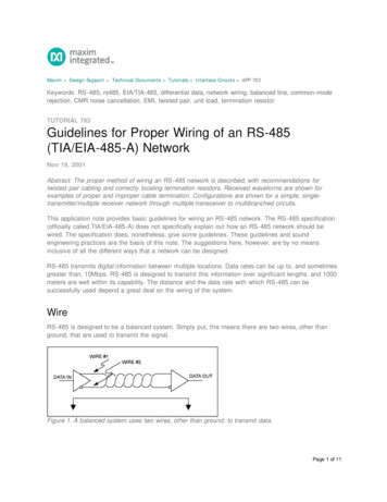
Electrical boxes:The most commonly used electrical boxesfor residential and cottage wiring projectsare octagonal, square, and device types.There are various sizes of boxes. The sizeyou use depends on the number and sizeof conductors, number of wire connectorsused, and whether or not a device suchas a receptacle or switch will be mountedin the box. When cables are installed inelectrical boxes, care must be taken toensure the proper size of box is used.Figure 3 illustrates the various types ofboxes most commonly used in residentialand cottage wiring.Figure 3 – Electrical boxesREMOVE ONE SIDE FROM EACH BOXThe most common size of octagonal boxused for residential wiring is 4 x 1.5 inches.You may install ten No. 14 AWG insulatedconductors or eight No. 12 AWGinsulated conductors in this size of box.If you need to install more conductors,then use a deeper box or employ anextension ring. The two most commonsizes of device boxes are 3 x 2 x 2.5 inchesand 3 x 2 x 3 inches. Where switches orreceptacles are to be installed in theseboxes, the maximum number of insulatedconductors that may be installed are:3x2x2.5 inchesfive – No. 14 AWG insulated conductors,orfour – No. 12 AWG insulated conductorsGANG SECTIONAL BOXESTOGETHER TO FORMLARGER BOXESOCTAGONAL OUTLETOR JUNCTION BOX3x2x3 inchesseven – No. 14 AWG insulated conductors,orfive – No. 12 AWG insulated conductorsBLANK COVERLAMPHOLDER COVERA 4 11/16 inch square box is requiredfor dryer and range receptacles.SQUARE JUNCTION BOX AND COVER12
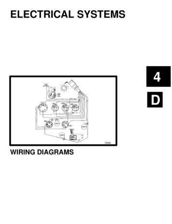
Switches:There are four common types of switches:single-pole, three-way, four-way, anddimmer.A single-pole switch controls a light orreceptacle from one location only. A three-way switch has three terminalsand operates in conjunction withanother three-way switch to control areceptacle or light from two locations. A four-way switch has four terminalsand is used in conjunction with twothree-way switches to control a lightor receptacle from more than twolocations. A dimmer switch allows you to turnan incandescent light on or off,and vary the brightness of the lightaccording to your needs.Figure 4 – Typical schematic diagrams SINGLE-POLE SWITCHTHREE-WAY SWITCHFOUR-WAY SWITCHFigure 4 illustrates the different typesof switches.Receptacles:There are several grades of receptaclesavailable. Receptacles in areas such asthe kitchen or driveway and those usedfor heavy loads should be of top quality,as they will be used constantly.DIMMERSWITCHSINGLE-POLE SWITCHTHREE-WAY SWITCHFOUR-WAY SWITCH13
CHAPTER III – TOOLS REQUIREDThe following are some of the toolsrequired to install electric wiring.(You may already have many of them.) Screwdrivers:- No. 8 Robertson- No. 6 Robertson- Standard Flat blade Pliers:- lineman’s pliers- multi-purpose diagonal cutters- needle nose pliers Miscellaneous:- Allen key- cable stripper- hammer- knife- power drill- voltage tester- wood drill bitsEquipment safety1. Always keep your power toolscleaned and lubricated, accordingto the manufacturer’s instructionsin the operating manual.2. Check power cords and extensioncords frequently. If the insulation isbroken or the power cord is frayed,replace it immediately. Do not try tofix it.3. Always disconnect equipment byremoving the plug from the electricaloutlet first. Then disconnect the cordfrom the power tool.4. Never operate power equipmentwhile standing on wet ground or inwater.5. When you have finished using yourpower tools, store them in a clean,dry place. Don’t leave them lyingaround unprotected.6. Be careful with extension cords.Run them along walls if possible, sothat no one will step on them or tripover them. Never set a heavy objecton an extension cord.14
CHAPTER IV – WIRINGOnce you have gathered the requiredtools and materials, and obtained yourelectrical permit, you will need to arrangefor electricity at your construction site.You may wish to have power at yourconstruction site to operate your powertools. There are several ways to do this:Have an electrician install a temporarybuilder’s electrical service on the site.For a nonrefundable installation fee,Manitoba Hydro will connect it. Borrow power from a neighbour,using a three-wire outdoor cord ofa sufficient size to prevent excessivevoltage drop due to the length ofthe cord. Have an electrician install yourpermanent building service and oneconvenience outlet in your home orcottage. For an additional inspectionfee, Manitoba Hydro will connect theservice prior to the installation ofrough-in wiring.Service inclu
in any electrical wiring or in any improper installation of electrical wiring resulting from the use of this Guide. You can view or print a copy of this guide on our website at hydro.mb.ca. If you have any questions or would like to make arrangements for an inspe