Transcription
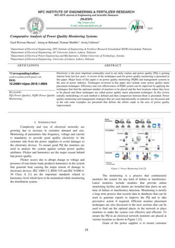
Engineering, 2010, 2, 46-54doi:10.4236/eng.2010.21006 Published Online January 2010 (http://www.scirp.org/journal/eng/).Vibration Monitoring of Rotating SystemsK. N. EDE1, E. A. OGBONNAYA2, M. T. LILLY3, S. O. T. OGAJI4, S. D. PROBERT41Method Engineer, Netco-Dietsmann Nigeria Limited, Port Harcourt, NigeriaDepartment of Marine Engineering, Rivers State University of Science and Technology, Port Harcourt, Nigeria3Department of Mechanical Engineering, Rivers State University of Science and Technology, Port Harcourt, Nigeria4School of Engineering, Cranfield University, Bedfordshire, United KingdomE-mail: kingston2004@yahoo.com, ezenwaogbonnaya@yahoo.com, s.ogaji@cranfield.ac.ukReceived June 6, 2009; revised August 3, 2009; accepted August 10, 20092AbstractMost energy-conversion machines (e.g. vehicle engines and electric motors) involve rotating components(e.g. roller bearings and gears), which generate vibrations. The behavior of a pump which includes a deliberate fault was chosen to illustrate this assertion. The test bearing at the driven end of the pump’s motor wasdeliberately damaged using a 1.5mm wire-cutting method and an adjustable coupling disk introduced to impose a shaft misalignment of 40. The resulting undesirable behavior of the pump was observed. Experimentaldata were measured at various speeds of the rotor. The sample period at various operating frequencies were0.9, 0.6 and 0.45s respectively. The ball-passage frequency was observed at 4.4, 8.8, 13.2 and 17.6Hz. Acomputer-based analytical model was developed, in visual basic, for monitoring the machine failures: thisled to an integrated system-process algorithm for diagnosis of faults in rotating components.Keywords: Vibration Measurement, Rotating Component, Ball-Passage Frequency, Alarm Limit1. IntroductionThe use of vibration analysis as a fundamental tool forcondition monitoring of equipment has evolved over thelast 35 years. With parallel developments in electronicequipment, transducers and computers, the monitoring ofmachines is now almost completely automated. Onboardmicroprocessors provide the ability to capture pertinentmeasurements and analyze them via suitable algorithms,then store and display the conclusions. Several accelerometers, velocity transducers and displacement pick-upshave been developed and adapted to suit the pertinentrequirement of industrial applications [1]. Modificationof a rolling-element bearing activity monitor (REBAM)system offers a high signal-to-noise ratio relative to thosefor a casing-mounted accelerometer or velocity transducer, as shown in Figure 1 [2]. A system’s signal-tonoise ratio is defined as the ratio of the amplitude of thedesired signal to the amplitude of the noise signal. Increased signal-to-noise ratios for accelerometers havebeen achieved through the use of electronic filters [3].REBAM vibration signals can be separated into rotorvibration and prime-spike regions. This signal separationimproves the signal-to-noise ratio for both regions. Bymeasuring directly the vibrations at the rolling-elementbearing outer-ring and displacements are relative to theCopyright 2010 SciRes.machine casing.This isolates the signal of interest from extraneousvibrations (e.g., due to structural resonances, steamthrottling, pump cavitation, gear noise, etc.) which often mask the bearing-defect signals when casingmounted transducers are employed. The results obtainedindicate that this signal separation technique makesREBAM twice to eight times more sensitive to bearingfaults than casing-mounted transducers [4]. A significant feature of this frequency analysis is the effectivecomputation of the fast Fourier-transformation (FFT),which converts digital information from the time domain to the frequency domain and thereby achieves amore rapid spectral-analysis [5].Long-term data storage is now a well accepted practice.However difficulties occurred when random-vibrationAccelerometer SystemShaft Relative System (Proximity probe observing theshaft’s surface)Velocity Transducer SystemREBAM System (Proximity probe observing the bearings outer ring)LowSignal-to-Noise RatioHighFigure 1. Qualitative indication of relative magnitudes ofsignal-to-noise ratios for various transducers.ENGINEERING
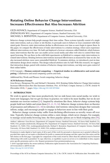
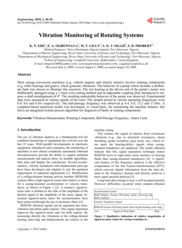
K. N. EDEenvelope spectrum algorithms for identifying defects inrolling-element bearings were applied to gearing. Extralines appeared in the envelope spectrum due to the dynamic loads applied to the bearings by the gears. Additionally, spectral lines associated with the rolling-elementdetector based on the power spectrum [7]. The ensuanteffective predictive maintenance can result in an 8%maintenance-cost saving and a further 8% increase inproductivity [8], and hence the associated energy-thrift.1.1. GlossaryAn accelerometer, in the present context, is a transducerwhose electrical or mechanical output is directly proportional to the acceleration experienced.An alarm limit is the maximum permitted predictedvalue of the considered parameter, i.e. it indicates whenattained that a dangerous situation is developing and sothe alarm is triggered.The ball-passage frequency is the frequency of the ballin a bearing component that will generate specific frequency dependent upon the bearing’s geometry and itsrotational speed.The bearing-passage frequencies are the frequencies ofrotation of the ball, outer race, inner race and cage.A coupling-disc or flexible connecting system is a robust general purpose pin/buffer coupling, that facilitatesa reliable fail-safe transmission of the torque betweentwo nominally-coaxial shafts; it possesses the capabilityof being able to function despite a misalignment of theshafts.A fast Fourier-transform is a numerical operationcommonly used for transposing data rapidly from thetime domain to the frequency domain, and usually accomplished via computer.The gap, in the present context, is the air-filled separation between the rotor and stator.Harmonics are components of a spectrum which areintegral multiples of the fundamental frequency.In the context of this article, imbalance (or a lack ofbalance) results from the distribution of mass accordingto the radial direction of the rotating system.Outer-race-ball passage frequency is the rate at whicha point on the specified rolling element passes a point onthe outer bearing-race.Inner-race-ball passage frequency is the rate at whicha point on the specified rolling element passes a point onthe inner bearing-race.Prime spike is a term used by Bently Nevada to describe a vibration frequency range which includes thosebearing frequencies that are generated by the rollingelements experiencing either an inner or outer race flaw.A probe, in the present context, is a sensor capable ofdetecting the vibration signal.The raceway is the ball passage frequency relative tothe inner and outer ring of the bearing.Rack-configuration software is a tool for configuringCopyright 2010 SciRes.ET AL.47bearings occasionally disappeared from the spectrum.Investigations were conducted in order to overcomethese complications [6]. This led to the introduction ofthe demerit of a bi-spectrum-based quickest-change detector, which was an extension of the analogous quickestintegrated control-switching. It is designed to have a3500/40 proximity monitor and a four-channel monitorthat accepts inputs that can trigger alarms.Rolling-element frequency is the frequency at whicheither the balls or rollers revolve about their own centerlines in a bearing.Ringing of the bearing occurs when ever the ball hitsthe flaw on the outer race of the bearing.A signal, in the present context, is an electric voltageor current, which is an analogue of the vibration beingmeasured.In the context of this article, Spike energy is a measureof the energy generated by the repetitive impacts of therolling elements against the defect in the bearing.A time base is a horizontal line (representing time)about which the waveform representing the vibrationsignal occurs, i.e. the representation of a vibration signalin the time domain is a wave form.A transducer is a device that converts the magnitude ofone physical parameter into the value of another parameter, usually an electrical signal. The transducer usedin vibration measurements is usually an accelerometer.2. The AimThis study investigates the occurrences of common machine-faults (i.e. rolling-element bearing and gear failures,misalignment of the shaft and imbalance of the shaft) thatlead to energy wastages. The bearings were tested whenundamaged and the resulting data were used as abench-mark. An accelerometer was employed to obtainthe vibration data from on-line measurements. The resulting information made available by the sensor and amplifier, was translated into useful knowledge about the forceson the machine and vibration patterns: the latter was classified according to the defects detected. Alarm limits weresetup and programmed for the data collected. Faultdiagnosis software (FDS) for vibration monitoring ofpumps and turbines has as a result been developed in thisinvestigation: this is available from the authors.2.1. InstrumentationThe characteristics of the employed standard vibrationmeasuring instrument for the applied range of 0.5to14000Hz, the power supply was a 4mA constant current at 23VDC, and 3 contact probes were available.Bently Nevada eddy-probes were installed on the test rig.A 3500/40 proximity four-channel monitor that acceptsinputs to drive the alarms and programs is shown schematically in Figure 2.ENGINEERING
K. N. EDE48ET AL.Local signal- conditionerRemote read-out instrumentLocal signal- conditionerOptional outputs foralarms/trips, recordingSeismic transducerand / or analysis instrumentof the ICSS.Local signal -conditionerNon-contacting transducerShaftLocal signal -conditionerFigure 2. The probe arrangement.2.2. Time Period SampledThe relationship between frequency and time is given as:F I/P(1)For this analysis, the instrument was set up to observethe shaft rotating at 10 or 15 revolutions per second.Total time (s) 60(Number of Revolutions) / RPM(2)With this instrument used, it became necessary to setan equivalent Fmax setting [9]. The appropriate Fmax setting can be calculated as;Fmax (CPS) Lines of revolution x RPM/60(No. of revolutions desired)(3)The SKF pattern No. 6226/C3 bearing used has a singlerow of balls. Because the defect was inflicted deliberatelyon the outer race of the ball bearing, at various speeds ofthe rotor, spikes were generated. These spikes corresponded to the outer race-ball passage frequencies [10].Readings collected while using this damaged bearing isshown in table. RPM Bd 1 cos z 2 * 60 Pd The cage rotating frequency, (ic) [10].ORBP 1 ic 2RPM* 60 (4) Bdcos Pd (5)Table 1. Standard bearing 6226(SKF) used in this investigation.Cage’s Rotating-Frequency(ic)0.49InnerRace-BallPassage Frequency(IRBP)5.29Copyright 2010 SciRes.OuterRace-BallPassage Frequency(ORBP)3.71RollingElement(iR)5.49A coupling disc was then designed so that it couldimpose a shaft misalignment onto the undamaged bearing. The disc was capable of moving relatively by adjusting the pin/buffer coupling. This forces the disc of70mm diameter on the shaft to move and produce anangular misalignment of 40.2.3. Bench-Mark AlarmThis type of alarm was used to trigger an alarm when themeasured value exceeds its bench-mark value times a coefficient, which in this case WAS assumed to be 1.5. That is,Threshold 1.5 (Bench mark value)(6)Vibration data were automatically compared withbench-mark values. User-defined alarm limits for thedata collected are illustrated in Table 2.3. Results and DiscussionsThe accelerometer was set up to record over a long timespan in order to observe the cycle of spike occurrencesfor probe data when the shaft was rotating at 10 or 15revolutions per second. The periods necessary to accomplish 10 and 15 revolutions at 17 RPS were 0.6 and 0.9srespectively, at 25 RPS are 0.4 and 0.6s respectively, andTable 2. User-defined upper and lower threshold alarmlimits.Type of alarm“High”DG 0AL 0AL0DG0“Low”DG 0AL 0AL0DG0Definition of AlarmDANGER if measured value DG ALARM if AL value DG Otherwise acceptable.DANGER if measured value DGALARM if DG- value ALOtherwise acceptable.ENGINEERING
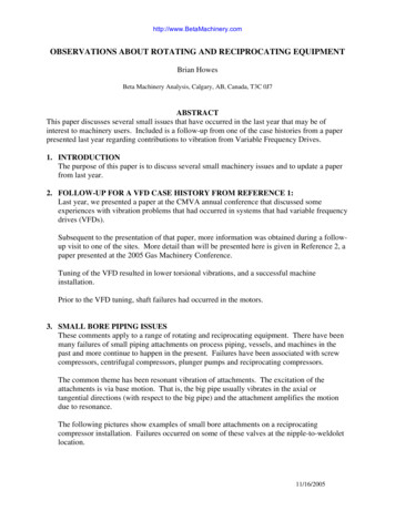
K. N. EDEat 33 RPS are 0.3 and 0.45 seconds respectively.When a ball was located near the point where theprobe is mounted (left side, 450 from the top) see Figure3, the outer race, due to the ball pressing on the defect,interacts and the resulting impacts excited a natural resonant frequency of the machine, caused the bearing to ring,and deform away from the bearing centre and towardsthe probe. This corresponds to the high peak-points inthe time-domain plot shown in Figure 4.ET AL.49450450L eft probeRight probeOuter race defect spot that comesinto contact with rollersω 3.1. Damaged Bearing4. Fault-Diagnostic Software (FDS) ProgramThis program was written in visual basic. It is an online-based data simulation and monitoring process for apump or turbine defects. The FDS was composed usingrack-configuration software. For this reason, the flowchart shown in Figure 6 was developed to describe theadopted monitoring procedure. The process acceptedbasic process information, such as acquired data or signals from a PLC on the ICSS on-line [11]. The electroniccontrol of the test equipment and the conventional connection of proximity probes for on-line data-acquisitionvia the PLC unit that was associated with the monitor(4-channel orbit analysis), therefore, was able to captureradial vibration, thrust position, and eccentricity. Themodule received input from many types of displacementtransducers.4.1. Vibration MeasurementsTo monitor this equipment on-line, the measured datawere compared with their preset threshold values (inCopyright 2010 SciRes.Amplitude (μm)Figure 3. Probe orientations and outer race defect spotcausing “ringing” of the Time (s)F
Prime spike is a term used by Bently Nevada to de-scribe a vibration frequency range which includes those bearing frequencies that are generated by the rolling elements experiencing either an inner or outer race flaw. A probe, in the present context, is a sensor capable of detecting the vibration signal.