Transcription
Cinematronics Vector Monitor Repair Guide v.1.0The Cinematronics Vector Monitor FAQ and Repair Guideby McClintockVersion 0.96February 28, 2003Table of ContentsINTRODUCTION . 2THEORY OF OPERATION . 4MONITOR TYPES AND DIFFERENCES . 15VARIABLE INTENSITIES . 17HIGH VOLTAGE SUPPLY . 19TUBE AND YOKE . 23MONITOR ADJUSTMENTS . 24FACTORY SERVICE UPGRADES. 26RECOMMENDED MONITOR UPGRADES . 28TROUBLESHOOTING AND TEST PROCEEDURES. 30SYMPTOM DIAGNOSIS. 35Appendix A: Operator's Guide To Troubleshooting. 43Appendix B: Replacement Parts. 46Appendix D: Testing Transistors. 48Appendix E: Using an Electrohome G05 or Wells-Gardner V2000. 50Appendix F: Installing A Cap Kit. 51Page 1 of 53
Cinematronics Vector Monitor Repair Guide v.1.0INTRODUCTIONNote: Very little, if any, of this document is my own work. Information in this document has beentaken from official factory manuals, technical updates, practical experience by others, etc. In manyinstances I have paraphrased or omitted information from the original documents for readabilityand/or clarity purposes. I thought it would be helpful, not only to myself, but to others havingtrouble with their Cinematronic vector monitors. Please read through this entire document beforeworking on your malfunctioning monitor, and make sure you have a set of schematics on-hand.Also, in order to properly test your Cinematronics monitor, it is imperative that you have a knownworking game board and power supply to provide a good input signal to the monitor. A bad gameboard and not the monitor can actually cause some of the symptoms of a ‘bad’ monitor. It is alsoimportant to say that an oscilloscope is a piece of test equipment that is necessary to work onCinematronic vector monitors. Without a scope, you will find it almost impossible to solve yourproblem(s).DISCLAIMERCAUTION!!! LETHAL VOLTAGES ARE PRESENT IN ARCADE MONITORS.SUITABLE PRECAUTIONS SHOULD BE TAKEN BEFORE ATTEMPTING TOSERVICE YOUR MONITOR. REMEMBER, NO WARRANTIES, EXPRESS ORIMPLIED, ARE GIVEN. USE THIS INFORMATION AT YOUR OWN RISK. I AM NOTRESPONSIBLE FOR ANY DAMAGES THAT MAY OCCUR TO YOUR PERSON ORPROPERTY.AcknowledgementsThe following people have contributed to the development of this document (knowingly orotherwise): Gary Akins Jr.; Rodger Boots; David Fish; David Haynes; John Hermann; MikeInglem; Mark Jenison; Al Kossow; Rich Marquette; Matt McCullar; Zonn Moore; John Robertson;Matt Rossiter; Mike Saul; Mark Shostak; Sam Verlander; Joe Welser; Simon Whittam; and GreggWoodcock (let me know if you want to see your name here – or don’t want to!)The Cinematronics design was created by one man - Larry Rosenthal. It is very elegant, andastounding that Larry’s design could do so much with so little.Cinematronics – related patents4,053,740 (Video game system) Rosenthal4,027,148 (Vector generator) RosenthalPage 2 of 53
Cinematronics Vector Monitor Repair Guide v.1.0To do:EXAMINE THE TAILGUNNER II SCHEMATICS FOR NOTESDetail Tailgunner joystick interfaceFind better scan of HV Oscillator (as seen in Star Tech Journal)Page 3 of 53
Cinematronics Vector Monitor Repair Guide v.1.0THEORY OF OPERATIONTo understand what goes on inside the Cinematronics monitor, we will first examine large generalgroups of circuits. This will help avoid confusion and aid in a basic, concrete, knowledge of whatmakes up the Cinematronics vector monitor. Having a good understanding of how the monitoroperates will greatly assist the reader in diagnosing and repairing their problems.Unlike other vector monitors such as the Electrohome G05, or Wells-Gardner 6100, theCinematronics Vectorbeam monitor is comprised of a single PCB that spans the width of themonitor frame. The Cinematronics monitor, while initially looking like a large mess ofcomponents, can be divided into two basic sections: one is the deflection amplifier and the other isthe voltage and cathode drive circuits (the HV) – just like other vector monitors. Some of thedescriptions herein may be a bit confusing at first. Hopefully after reading the entire document,things should become clearer. Grab some schematics and follow along.Page 4 of 53
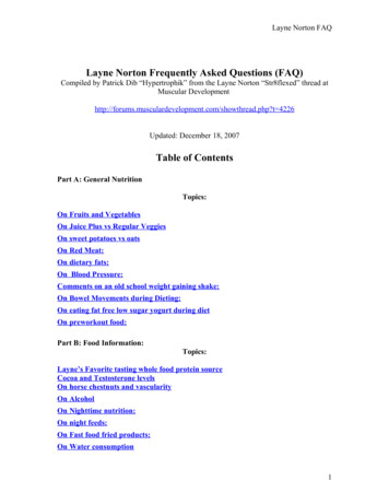
Cinematronics Vector Monitor Repair Guide v.1.0DEFLECTION AMPLIFIER CIRCUITThe deflection amplifier circuit can be further divided into two identical channels: one for thehorizontal deflection (“X”) and one for the vertical deflection (“Y”). Because both channels areidentical, we will only discuss the horizontal channel in this document.The deflection circuit receives digital numbers from the logic board that represent the coordinatesfor the beginning and end points of each line segment. The deflection circuit output is a current sentto the yoke windings that is proportional to these numbers. So, the purpose of the deflectioncircuitry is to convert a binary coded number into a current. This conversion is accomplished withthe following components.DAC – Digital to Analog ConverterThe first step in creating an image on the screen is to convert the digital coordinate numbers into ananalog voltage. The DAC-80 is the device that does this.Digital information from the Cinematronics CPU (the “CCPU”), in the form of a twelve-bit word,is applied to the input of the DAC-80 digital to analog converter (IC101) on pins one throughtwelve. The most significant bit is applied to pin one, and the least significant bit is applied to pintwelve. The DAC-80 makes the necessary conversion from digital signals to analog signals, whichare outputted as analog voltage signals on pin fifteen (proportional in level depending on the inputword applied). The result is a positive and negative voltage signal about its reference voltage.Remember, there is no "sync" signal present, and the signal is not true video as seen in raster scanmonitors.Pins one through twelve of the DAC can represent any number between –2,048 and 2,047. Theoutput voltage range is from –5 volts to 5 volts. When the DAC is operating properly, the outputsignal is centered about 0 volts and bounded between /-5 volts.DAC CIRCUITPage 5 of 53
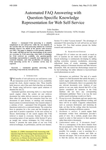
Cinematronics Vector Monitor Repair Guide v.1.0Analog SwitchFrom the DAC-80 the analog signal is then sent to a high-speed analog switch, ICl. The analogswitch has two parallel inputs for the display signal, and two controlling inputs, which select one oftwo outputs from the switch.The LF133310 analog switch at location IC1 is the most active component on the monitor. Both thehorizontal and vertical DAC output voltages pass through this switch and then become convertedinto currents to deflect the beam to proper positions on the screen. The chip is mounted in a socketfor easy removal and should be a prime suspect for monitor that blows circuit breakers.The switch passes the voltage output of the DACs through either of 2 channels: the lower channelis for the initial position coordinate of a line segment, and the upper channel is for the finalcoordinate. The CCPU controls the channels: initial position on pin 8 and line drawing (finalcoordinate) on pin 1. If the upper channel in the switch is defective, say, in the horizontal section,then there will be no horizontal lines on the display. The same is true for the vertical.Output fifteen from the switch routes the analog signal through a 5K potentiometer (R102), a 10Kresistor, (R103) and to the input of the TL081 op-amp (IC102). The time constant developed bythese two resistors and the capacitor (C101) determine the length of the vector line seen on thescreen. Adjusting the potentiometer will adjust the length of the vertical lines seen on the screen.Output ten from the analog switch routes the signal directly to the input of the TL081 op-amp, andthe resulting voltage across C101 determines the initial starting position of the vector. R130 is thereto protect the analog switch from any damage caused by the large inrush currents when chargingC101. The CCPU is responsible for waiting until C101 is fully charged to its initial voltage beforeturning on the Z-axis.ANALOG SWITCH CIRCUITPage 6 of 53
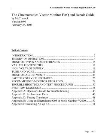
Cinematronics Vector Monitor Repair Guide v.1.0R/C NetworkThe voltage across a resistance-capacitance (“R/C”) network, found at the outputs of the analogswitch IC1, is used to draw screen vectors. The R/C network is responsible for drawing smooth,straight and precisely positioned vectors. The voltage across the R/C network, at any given time,determines the actual position of the CRT trace at that time. As the capacitor charges, and thevoltage changes, the CRT trace follows, and the vector is drawn.Initial position voltages enter from the lower switch channel directly across C101, which charges tothat voltage level rapidly. The voltage is converted to an initial position current by the deflectionamplifiers, positioning the beam at the beginning point of a line segment.Final position data from the upper switch channel slowly charges C101 through R103 and linelength pot R102. As C101 charges from its initial point value to its final value, a straight horizontalvector is drawn. Since all this is happening at the same time in the vertical section, a vertical vectoris also being drawn. The combination of both sections moving the CRT beam simultaneouslyallows for a vector of any angle to be drawn. Both R/C networks charge simultaneously, whichallows the CRT trace to simultaneously move in the vertical and horizontal direction, so that avector can be drawn at any angle.Pot R102 varies the charge rate of the network, and can lengthen (slower charge) or shorten (fastercharge) the vector for the “on” period of the beam.R/C NETWORK CIRCUITPage 7 of 53
Cinematronics Vector Monitor Repair Guide v.1.0Edge Gain AmplifierIt is a property of the CRT that, near the edges of the screen, the amount of current needed to movethe beam, say, an inch, is less than the amount required to deflect the beam an inch off center.Therefore, less gain is required near the edges of the CRT.The edge gain amplifier is the final stage before the voltage-to-current conversion process. Theinput on pin 3 of IC102 (or IC202) is a waveform that is the composite initial position and finalposition data signals. The amplifier has an overall gain of about 2x at output pin 6. The waveformshould resemble the DAC output, but is now bounded between /- 2 volts, centered about 0 volts.The TL081 op-amp at IC102 serves a dual purpose: it acts as a buffer between the deflectionamplifiers and the analog switch, as well as an "edge gain" amplifier (i.e., height).At the output of IC102, there is a resistor diode network consisting of R105, R106, R107, R108 andD101, D102, D103, D104. This resistor diode network is used to compensate for the non-linearcharacteristics of the CRT near the edges of the screen. If this circuit were not used, any objectdisplayed on the screen would increase in size as it moved closer to the edges of the screen.The amplifier circuit reduces gain as the output voltage increases, indicating a larger beamdisplacement, by switching on diodes D101 and D102 for the upper half of the screen, and D103and D104 for the lower half. This places R106 and R107 in parallel with R105, reducing its valueand consequently the gain. If a figure increases in size near the display edges, a diode in thissection is open.Potentiometer R109 is the vertical picture size control. By picking off larger or smaller voltages,the height of the picture is controlled.EDGE GAIN AMPLIFIER CIRCUITPage 8 of 53
Cinematronics Vector Monitor Repair Guide v.1.0Deflection AmplifierThe deflection amplifier converts the pick off voltages from the size pot (R109) into a current thatdrives the deflection yoke winding. The input is a differential stage consisting of transistors Q101,Q103 and Q102. Q101 is an emitter coupled with Q103 to provide a degenerative feedback loopfrom the yoke. Q102 is a reference current source to both emitters and a fixed amount of currentalways flows through it. If this current varies, the picture will be offset from center. Too muchoffset will cause the circuit breakers to blow.This reference current is determined by the voltage drop across R113. Diodes D105 and D106determine this drop. The voltage across one of the diodes is cancelled by the base-emitted voltageof Q102. R113 should constantly read 0.6 volts DC. This means a constant flow of about 3mAthrough Q102.This 3mA bias must come from the emitters of Q102 and Q103. Excess current is picked off at thecollector of Q101 and feeds pre-driver Q104. The reference current source for pre-driver Q104 isQ105, D107, D108 and R116. Bias current through R116 is about 0.22mA.At this point, the deflection circuit can again be divided into two identical circuits. One circuit,which controls the lower half of the screen, is comprised of Q104, Q106, Q108 and Q110. Theother circuit, which controls the upper half of the screen, is comprised of Q105, Q107, Q109 andQ111.1Q104, Q108 and Q110 are three stages of amplification, while Q106 is used as current limitingprotection for Q108 and Q110. The same holds true for the other configuration of Q105, Q107,Q109 and Q111.Current is delivered to the yoke in a push-pull manner by transistor pairs Q108 and Q110 forpositive current translations. Q110 and Q111 are power driver transistors mounted on thehumongous heatsinks on the left side of the monitor frame.Diodes D109, D110 and D111 set up a crossover voltage threshold to prevent both halves of thepush-pull output from turning on at the same time. Should one of the diodes open, only half of adisplay will be generated. Should the diodes become resistive, both power transistors will turn onsimultaneously and generate excessive heat.If more than 3 amps are drawn through sense resistors R120 and R121, transistors Q106 and Q107turn on and shut off the power driver by sinking the base current to drivers Q108 and Q109. Thisprotects the hardware against further damage.R124 through R129 are used as a current divider network for the yoke. R122, R123, and C102 forma R/C network, which compensates for any counter EMF that may develop by the expanding andcollapsing of the deflection coil's electromagnetic field. Revision B and later monitors do not1In the horizontal section of the deflection amplifier, Q205, Q207, Q209 and Q210 control the left hand side of thescreen, and Q204, Q206, Q208 and Q211 control the right hand side of the screen. By dividing the screen in thismanner, four quadrants of deflection area have been developed.Page 9 of 53
Cinematronics Vector Monitor Repair Guide v.1.0incorporate R122, as it was only required to compensate for non-linearity in the early productionyokes. Monitors in Space Wars games utilized R122.If there is a problem with the upper half of the picture, it is with the circuit elements connected tothe –25 volt line in the deflection amplifier. If, say, the lower half of the picture is missing, suspectthe elements connected to the 25 volt side of the horizontal deflection amplifier.DEFLECTION CIRCUITPage 10 of 53
Cinematronics Vector Monitor Repair Guide v.1.0HIGH VOLTAGE SUPPLYThe high voltage and cathode circuitry is the second section of the Cinematronics monitor. Thissection also contains the necessary voltage regulation to power the ICs located on the displayboard.For the early ‘discrete’ – style monitors, IC3 (7818) and IC5 (7918) provide positive 18V andnegative 18V used in the high voltage transformer (T-l) and oscillator (the oscillator circuit isnecessary because there is no horizontal sync used to develop the high voltage pulses). Theoscillator circuit is comprised of primary windings, Q4 and associated discrete components. For thelater ‘Keltron’ – style monitors, IC4 (7815) and IC6 (7915) provide positive 15V and negative 15Vrespectively to power the DAC-80s and the TL081 op-amps on the display board.The high voltage (18KV on discrete HVs and 16KV on non-discrete ‘Kelton’ HVs) is developed byTransformer T1’s secondary windings, and the high voltage tripler in the discrete design. TheKeltron contains what is called the high voltage quadrupler – even though it produces less voltagethan the discrete version.Intensity Circuit (‘Z’ Channel)The beam can be turned on and off by applying the proper voltage level to the CRT cathode. Beamcut off is 90 volts DC. At this potential, the electrons excited by the filament prefer to remain onthe cathode and none make it to the screen of the CRT. Lowering this potential allows moreelectrons to escape to the anode. We can then produce a NORMAL INTENSITY level by loweringthe cathode potential to 40 volts DC, and a HIGH INTENSITY by lowering the potential to, say, 20 volts DC.The Cinematronics CPU produces two intensity levels by sending low pulses to pins 1 and 3 of IC7(7406). Pin 1 is the HI INTENSITY channel and consists of IC7 and Q1. The NORMALINTENSITY channel consists of another part of IC7 and Q3. The CCPU also has a jumper settingto produce variable intensities, but this option is only used on two games - Sundance (16 intensitylevels) and Solar Quest (64 intensity levels). These additional intensity levels are produced withadditional PCBs that are discussed in the following section.The intensity and beam blanking control circuitry is composed of IC7, Q1, Q2, Q3, Q7 and Q8 andassociated components. A beam blanking voltage of 90 volts DC is generated from pin 8 of theHV transformer secondary winding, D6 and C17. This half wave rectifier supplies the 90 volts toone terminal of the brightness pot. The wiper of this pot picks off the proper voltage and sends itthrough the yellow cathode wire to the CRT plug socket. R11 adjusts the amplitude of the negativespikes used for brightness and intensification. A greater negative spike creates a brighter picture.The cathode voltage rides at 90V, and the beam is turned “on” by negative voltage. Using anoscilloscope, negative pulses can be seen at the anode of D4. These are the beam “on” pulses. Fornormal intensity the pulses will go down to approximately 40V, for double intensity, 20V. Pins 3and 4 of IC7 are the normal intensity control gate which receives information from the CCPU. Pin1 and 2 of IC7 are the double intensity control gate. When a Hi going Lo signal is on pin 3 of IC7,pin 4 will be a Lo going Hi, turning on Q3 on the Hi transition. Q3 acts as a switch connecting theseries network of R11, R10 and R9 to ground creating a voltage divider network. R11 is the manualintensity control. When pin 2 of IC7 goes Hi, Q1 turns on for the duration of the pulse connectingPage 11 of 53
Cinematronics Vector Monitor Repair Guide v.1.0just R9 and R11 to ground, thus lowering the voltage at the anode of D4 even more because of thelower resistance, than with normal intensity. Q2 is used as a switch to enable Q1 and Q3. Q2’spurpose is to shut off the beam when the power is turned off. Q7 is a beam “on” delay to preventphosphor burns if someone was to unplug and plug in the machine rapidly. With Q1 and Q3 bothoff, or Q2 off, current has no path to ground and the wiper voltage will be 90 volts regardless ofthe brightness pot setting.For a NORMAL INTENSITY vector, pin 3 of IC7 pulses low. Pin 4 then pulses high to 2.75volts, turning on Q3. Current flows through R11, R9, R10 and through Q3 to ground via Q2. Thisdrops the voltage at the cathode to about 40 volts with the brightness pot full clockwise.For a HI INTENSITY vector, pin 1 of IC7 pulses low. Output pin 2 pulses high to 2.75 volts,turning on Q1. Current flows through R11, R9, through Q1 and to ground via Q2. This drops thecathode level to about 20 volts with the brightness pot full clockwise.The yellow wire to the cathode should show a 90 volt DC base with negative going pulses thatvary as the brightness pot it turned. For a no display condition, suspect IC7. The 7406 chip is anopen collector inverter and must have a pull-up resistor on its output. Verify that 4 to 5 volts isalways present at the junction of R1 and R2. This voltage is supplied by Q8, which is in an R/Cdelay circuit to allow all voltages to settle on power up before a picture is displayed.Q2 is designed to open the intensity circuit immediately after power is removed from the game.This prevents the 90 volt blanking voltage from bleeding off before the high voltage bleeds off,thus preventing a spot becoming burned on the CRT screen when the game is unplugged. Q2 iskept on continually by a full wave rectified, unfiltered signal from the power supply through fuseF1 (0.5 amp). For a no display condition, eliminate Q2 as a source of trouble by jumpering itcollector to emitter, being careful to remove the short before powering down the monitor, since thisshort does eliminate the power down spot killer.INTENSITY CIRCUITPage 12 of 53
Cinematronics Vector Monitor Repair Guide v.1.0Spot Killer Protection CircuitryTransistor Q2 can be considered as the master intensity control switch. When it is deprived of itsbase drive, the collector-emitter junction opens and eliminates the ground path for the intensitychannels, cutting off the beam. The game logic board can fail in such a way as to cause the beam toremain on continuously, burning the CRT phosphor.R25 and C24 form an R/C time constant of about 6.8ms. Since most of the vectors on the displayrequire only microseconds of beam time, any turn on pulse from the CCPU, which is 6.8ms orwider constitutes a failure mode. The outputs of IC7 (pins 2 and 4) are sampled by Q6, whichinverts the pulses and feeds them back into IC7 on pin 11.When the input is high, the output transistor turns on and essentially shorts pin 10 to ground. Whenthe input is low, the transistor turns off and opens the circuits. So, for example, a high pulse at IC7,pin 4 of 10ms duration becomes a low pulse at the collector of Q6. This causes IC7 pin 10 to openthe circuit, allowing C24 to charge. Since the pulse width is greater than 6.8ms, C24 has ampletime to charge and turns on Q7, which shorts the base of the master intensity switch Q2, killing thedisplay.An additional protection circuit involves R20, R21 and pins 9 and 8 of IC7. Pin 9 is normally heldnegative by the voltage divider of R20 and R21. Should the circuit breakers blow and we lose -25volts, pin 9 of IC7 goes positive, causing pin 8 to short the base of Q2, again killing the display.SPOT KILLER PROTECTION CIRCUITPage 13 of 53
Cinematronics Vector Monitor Repair Guide v.1.0High Voltage Oscillator (early discrete monitor only)The HV Oscillator only appears in the discrete HV Cinematronics monitors (all monitors prior toRev.G). This circuit is incorporated into the Keltron HV box for later monitors. The integralelements of the HV oscillator section are IC9, IC5, Q4 and flyback transformer T1. The /-18Vregulators IC9 and IC5 deliver 36 volts across C18. The frequency of oscillation is dependant onthe winding characteristics of the HV Transformer, T1. As current begins to flow through pin 4 ofT1, a reverse potential is induced in the thicker coil at pins 1 and 2, tending to shut off Q4. Q4 turnson again after the R14/C19 time constant discharges, repeating the cycle. The tank circuit of D8,R15 and C20 provide a protective sink circuit against inductive spikes that must otherwise crippleTIP51C. Diode D7 protects against reverse currents.The secondary windings of T1 generate an 800-volt peak-to-peak waveform at pin 7 that is halfwave rectified by D10 and filtered by C22 to provide 400 volts DC of focus control.Beam cutoff voltage ( 90 volts DC) is supplied by a 200-volt peak-to-peak signal on pin 8,rectified by D6 and filtered by C17.[insert scan from Rip Off manual]VoltagesThere are several voltage regulators in the monitor: 18V, 15V, -18V, -15V. These are fed by a 25V and a -25V source. If one or more of these voltages were incorrect, that would easily causedeflection problems. The 18V (7818) and –18V (7918) regulators can be replaced with /-15Vregulators. A detailed discussion is included in the Factory Service Upgrade section of thisdocument.Page 14 of 53
Cinematronics Vector Monitor Repair Guide v.1.0MONITOR TYPES AND DIFFERENCESNow that we have discussed the operating theory of the Cinematronics monitor, we need to notethe different types. There are several revisions of the Cinematronics ‘vectorbeam’ monitor.However, there are two distinct versions – the “discrete” HV version and the “Keltron” version.The table below outlines the different revisions that are detailed in each schematic package. Do notassume your game has the original or correct monitor in it! Operators (and collectors) are known toswap things around. Also note that these monitor revisions are different and independent from theCCPU revisions. Do not confuse the two!The monitors produced by Larry Rosenthall’s Vectorbeam company are for all intensive purposesidentical to the monitors made by Cinematronics and differ in name only.CinematronicsSpace WarsStar HawkSundanceTail GunnerRip OffStar CastleArmor AttackSolar QuestRev. A (‘discrete’) 19” B&W monitorRev. B (‘discrete’) 19” B&W monitor (some with 23” B&W monitor)Display with 16 Level Intensity – Rev. ? (‘discrete’) 23” B&W monitorRev. D (‘discrete’) 19” B&W monitorRev. B (‘discrete’) 19” B&W monitorRev. G (‘Keltron’) 19” B&W monitorRev. G (‘Keltron’) 19” B&W monitorDisplay with 64 Level Intensity - Rev A. (‘Keltron’) 19” B&W monitorVectorbeamSpace WarBarrierWarriorSpeed FreakRev. H (effectively a Cinematronics Rev. B ‘discrete’) 19” B&W monitorRev. H (effectively a Cinematronics Rev. B ‘discrete’) 19” B&W monitorRev. H (effectively a Cinematronics Rev. B ‘discrete’) 19” B&W monitorRev. H (effectively a Cinematronics Rev. B ‘discrete’) 19” B&W monitor[The Vectorbeam monitor has an extra 2n2102 (Q19 on the Vectorbeam monitors; Q8 ona Cinematronics - 2N3904)]Exidy IITailgunner II?Rock-OlaDemonRev. ? (‘Keltron’) 19” B&W monitor[Boxing Bugs and QB-3 (you have one of those, right?) each used a Wells-Gardner 6100 colorvector monitor. War of the Worlds was supplied as a kit and was intended to be installed into aStar Castle or Armor Attack. A couple War of the Worlds prototypes used the Boxing Bugs coloradapter board with a Wells-Gardner 6100 color vector monitor. Therefore, none of these gamesare included in the above list.]Page 15 of 53
Cinematronics Vector Monitor Repair Guide v.1.0Analog Joystick Interface [need better description]The reading of a Joystick is nearly the same as Vectrex. A value is placed in the shared Y axisDAC, a reading from a comparator is taken and returned as a single Hi/Lo bit, it’s up to thesoftware to do whatever type of binary search it takes to determine the joysticks value. The joystickshares the DAC.Page 16 of 53
Cinematronics Vector Monitor Repair Guide v.1.0VARIABLE INTENSITIESTwo Cinematronics games utilized variable intensities – Sundance and Solar Quest. Essentially,these games are able to reproduce continuous fades (in or out) instead of just Normal and Hiintensities. Very cool effect. You can play any variable intensity game (i.e., Sundance or SolarQuest) on a two intensity (Hi/Lo) monitor by changing a jumper on the game CPU board. Thevariable intensity game ends up playing with all Hi intensity vectors and is thereforemonochromatic. For instance you can play Solar Quest on an Armor Attack monitor, but you can'tplay Armor Attack on the Solar Quest monitor without making a lot of changes to the monitor toremove the add-on intensity board.However, for testing purposes you can use a Solar Quest monitor with a CCPU that does not havethe multi-intensity jumper set. Although each time the intensity bit is changed on the CCPU gameboard you are using, some random value based on the last vector position will be latched as the Zintensity. If this results in intensities of blank, then you won't see much. It shouldn't hurt anythingto try.Sundance 16-Level Intensity PCB[?]Solar Quest 64-Level Intensity PCBSolar Quest uses a slightly different monitor than all the other games. Most Cinematronics gameshave a tri-state (2-bit) intensity, which is off/low/high. In Star Castle, for example, walls that havenot been hit are “high” intensity and walls that have been hit once are “low” intensity. Solar Questhas a little vertical board mounted on the back of the monitor frame. The ribbon cable from thelogic board goes first to this board and then on to the main monitor board. This board has a bunchof transistors, which apparently make up a 6-bit DAC for the 64-level intensity. As with the gameboards, they figured they could save money by designing their own circuits instead of using offthe-shelf ICs; Cinematronics really liked discrete components, which is a good thing sincereplacements for 74-series TTL, and plain transistors will be around for a LONG time and makerepair possible.Intensities for Solar Quest are done by using the same data lines that are used to drive the Y DAC,to send a 6-bit value to a latched intensity DAC. Color apparently uses the same lines, but 12 bitsare latched into the R G B level DACs.Solar Quest Intensity PCB connectionIf you want to convert your Rev.G monitor into a Solar Quest monit
The TL081 op-amp at IC102 serves a dual purpose: it acts as a buffer between the deflection amplifiers and the analog switch, as well as an "edge gain" amplifier (i.e., height). At the output of IC102, there is a resistor diode network consisting of R105, R106, R107, R108 and D101, D102, D103, D104.