Transcription
DYNAMIC ENGINEERING150 DuBois, Suite CSanta Cruz, CA 95060(831) 457-8891 Fax (831) 457-4793http://www.dyneng.comsales@dyneng.comEst. 1988User ManualPMC-BISERIAL-III MDS1Four-Channel Manchester EncodedSerial InterfacePMC ModuleRevision BCorresponding Hardware: Revision C10-2005-0203Corresponding Firmware: Revision B
PMC-BiSerial-III MDS1Four-Channel Manchester-EncodedPMC Based Serial InterfaceThis document contains information ofproprietary interest to Dynamic Engineering. Ithas been supplied in confidence and therecipient, by accepting this material, agrees thatthe subject matter will not be copied orreproduced, in whole or in part, nor its contentsrevealed in any manner or to any person exceptto meet the purpose for which it was delivered.Dynamic Engineering has made every effort toensure that this manual is accurate andcomplete. Still, the company reserves the rightto make improvements or changes in theproduct described in this document at any timeand without notice. Furthermore, DynamicEngineering assumes no liability arising out ofthe application or use of the device describedherein.Dynamic Engineering150 DuBois, Suite CSanta Cruz, CA 95060(831) 457-8891FAX: (831) 457-4793The electronic equipment described hereingenerates, uses, and can radiate radiofrequency energy. Operation of this equipmentin a residential area is likely to cause radiointerference, in which case the user, at his ownexpense, will be required to take whatevermeasures may be required to correct theinterference. 2005-2007 by Dynamic Engineering.Other trademarks and registered trademarks are owned by their respectivemanufactures.Manual Revision B. Revised April 17, 2007Dynamic Engineering’s products are notauthorized for use as critical components in lifesupport devices or systems without the expresswritten approval of the president of DynamicEngineering.Connection of incompatible hardware is likely tocause serious damage.Embedded SolutionsPage 2 of 32
Table of ContentsPRODUCT DESCRIPTION6THEORY OF OPERATION10PROGRAMMING12ADDRESS MAP13Register DefinitionsPB3 MDS1 BASEPB3 MDS1 USER SWITCHMDS1 CHAN0-3 CONTROLMDS1 CHAN0-3 STATUSMDS1 CHAN0-3 WR DMA PNTRMDS1 CHAN0-3 RD DMA PNTRMDS1 CHAN0-3 FIFOMDS1 CHAN0-3 TX AMT LVLMDS1 CHAN0-3 RX AFL LVLMDS1 CHAN0-3 TX FIFO COUNTMDS1 CHAN0-3 RX FIFO COUNT141415161821212222222323Loop-back24PMC PCI PN1 INTERFACE PIN ASSIGNMENT25PMC PCI PN2 INTERFACE PIN ASSIGNMENT26BISERIAL III FRONT PANEL I/O PIN ASSIGNMENT27APPLICATIONS GUIDE28Interfacing28CONSTRUCTION AND RELIABILITY29THERMAL CONSIDERATIONS29Embedded SolutionsPage 3 of 32
WARRANTY AND REPAIR29Service PolicyOut of Warranty Repairs3030For Service Contact:30SPECIFICATIONS31ORDER INFORMATION32SCHEMATICS32Embedded SolutionsPage 4 of 32
List of FiguresFIGURE 1FIGURE 2FIGURE 3FIGURE 4FIGURE 5FIGURE 6FIGURE 7FIGURE 8FIGURE 9FIGURE 10FIGURE 11FIGURE 12FIGURE 13FIGURE 14FIGURE 15FIGURE 16FIGURE 17FIGURE 18PMC-BISERIAL-III BLOCK DIAGRAMPMC-BISERIAL-III MDS1 BLOCK DIAGRAMPMC-BISERIAL-III MDS1 - DATA ENCODINGPMC-BISERIAL-III MDS1 XILINX ADDRESS MAPPMC-BISERIAL-III MDS1 BASE CONTROL REGISTERPMC-BISERIAL-III MDS1 USER SWITCH PORTPMC-BISERIAL-III MDS1 CHANNEL CONTROL REGISTERPMC-BISERIAL-III MDS1 CHANNEL STATUS PORTPMC-BISERIAL-III MDS1 WRITE DMA POINTER REGISTERPMC-BISERIAL-III MDS1 READ DMA POINTER REGISTERPMC-BISERIAL-III MDS1 RX/TX FIFO PORTPMC-BISERIAL-III MDS1 TX ALMOST EMPTY LEVEL REGISTERPMC-BISERIAL-III MDS1 RX ALMOST FULL LEVEL REGISTERPMC-BISERIAL-III MDS1 TX FIFO DATA COUNT PORTPMC-BISERIAL-III MDS1 RX FIFO DATA COUNT PORTPMC-BISERIAL-III MDS1 PN1 INTERFACEPMC-BISERIAL-III MDS1 PN2 INTERFACEPMC-BISERIAL-III MDS1 FRONT PANEL INTERFACEEmbedded SolutionsPage 5 of 326811131415161821212222222323252627
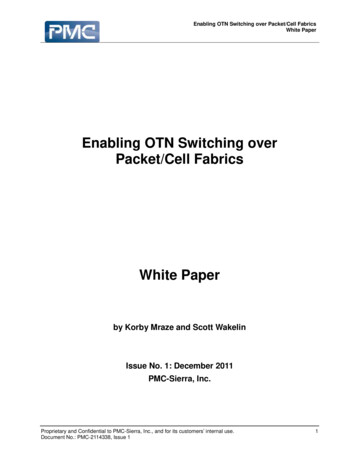
Product DescriptionThe PMC-BiSerial-III MDS1 is part of the PMC Module family of modular I/Ocomponents by Dynamic Engineering. The PMC-BiSerial-III is capable of providingmultiple serial protocols using either LVDS or RS-485 I/O standards.FIGURE 1PMC-BISERIAL-III BLOCK DIAGRAMThe PMC-BiSerial-III standard configuration shown in Figure 1 has two optional dataFIFOs that can be as large as 128k x 32-bit to accommodate designs requiring a largeamount of buffering. In most designs these FIFOs are not installed and internal FIFOsimplemented using the block RAM in the Xilinx FPGA are used instead.The MDS1 protocol implemented provides four channels each consisting of an RS-485transmit data and receive data using Manchester encoding. The on-board PLL is usedto generate the two clocks required for the design. The PLL is programmable and usesEmbedded SolutionsPage 6 of 32
a 40 MHz reference oscillator to generate a wide range of frequencies. The target ratefor this design is 192 kbits/sec. The transmitter uses a double-rate clock to encode theManchester output and the receiver uses an eight times clock to detect and decode theManchester input. The receiver can adapt to a range of frequencies from approximately0.75 to 1.25 of the target frequency.Other custom interfaces are available on request. We will redesign the state machinesand create a custom interface protocol that meets your requirements. That protocol willthen be offered as a “standard” special order product. Please see our web page forcurrent protocols offered. Please contact Dynamic Engineering with your customapplication.The MDS1 implementation has two 1K by 32-bit FIFOs using the Xilinx internal blockRAM, one for the transmitter and one for the receiver. Data is received MSB first inblocks of 81 16-bit words. Each data-block is preceded by a 16-bit sync pattern(0xAAAA). The idle time between data blocks is approximately 20 milliseconds and isfilled with Manchester encoded zero’s.All 81 data words end with a binary 01 tag sequence which leaves 14 significant bits ofdata. The first 80 words in the data-block are thermocouple voltages represented infloating point format. The 81st word contains the 8-bit unit ID in bits 14-7.The transmitter is used only for testing the receiver which is the focus of the design.The transmitter will send data when it is enabled and there are at least 41 32-bit wordsin the transmit FIFO. It sends the 16-bit sync pattern and then sends 81 16-bit wordsstarting with the lower half of the first 32-bit FIFO word followed by the upper half. Onlythe lower half of the 41st FIFO word is sent; the upper half is discarded.Thirty-four differential I/O are available at the front bezel for the serial signals. Thedrivers and receivers conform to the RS-485 specification (exceeds RS-422specification). The RS-485 input signals are selectively terminated with 100Ω. Thetermination resistors are in two-element packages to allow flexible termination optionsfor custom formats and protocols. Optional pullup/pulldown resistor packs can also beinstalled to provide a logic ‘1’ on undriven lines.This design uses only eight of the I/O lines, one in and one out for each of the fourchannels.Embedded SolutionsPage 7 of 32
FIGURE 2PMC-BISERIAL-III MDS1 BLOCK DIAGRAMThe PMC-BiSerial-III MDS1 conforms to the PMC and CMC draft standards. Thisguarantees compatibility with multiple PMC Carrier boards. Because the PMC may bemounted on different form factors, while maintaining plug and software compatibility,system prototyping may be done on one PMC Carrier board, while final systemimplementation uses a different one.The PMC-BiSerial-III MDS1 uses a 10 mm inter-board spacing for the front panel,standoffs, and PMC connectors. The 10 mm height is the "standard" height and willwork in most systems with most carriers. If your carrier has non-standard connectors(height) to mate with the PMC-BISERIAL-III MDS1, please let us know. We may beable to do a special build with a different height connector to compensate.Various interrupts are supported by the PMC-BiSerial-III MDS1. An interrupt can beEmbedded SolutionsPage 8 of 32
configured to occur at the end of a received or transmitted message. Also interruptscan be generated when the receiver is inactive for more than four bit periods or whenthe receive FIFO overflows (attempt to write to a full FIFO). All interrupts areindividually maskable, and a master channel interrupt enable is also provided to disableall interrupts for a channel simultaneously. The current status is available making itpossible to operate in a polled mode when interrupts are disabled. All configurationregisters support read and write operations for maximum software convenience. Alladdresses are long word (32-bit) aligned.Embedded SolutionsPage 9 of 32
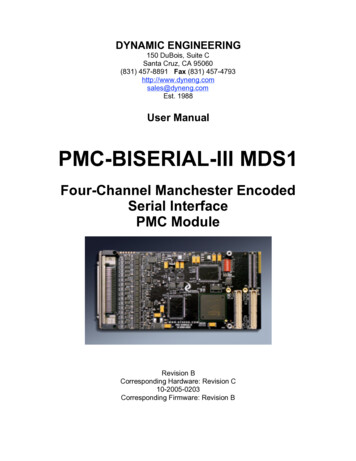
Theory of OperationThe PMC-BISERIAL-III MDS1 features a Xilinx FPGA. The FPGA contains all of theregisters, FIFOs and protocol controlling elements of the PMC-BISERIAL-III MDS1design. Only the transceivers, switches and PLL circuit are external to the Xilinx device.The PMC-BISERIAL-III MDS1 is a part of the PMC Module family of modular I/Oproducts. It meets the PMC and CMC draft Standards. In standard configuration, thePMC-BISERIAL-III MDS1 is a Type 1 mechanical with only low profile passivecomponents on the back of the board, one slot wide, with 10 mm inter-board height.Contact Dynamic Engineering for a copy of this specification. It is assumed that thereader is at least casually familiar with this document and basic logic design.A logic block within the Xilinx controls the PCI interface to the host CPU. The PMCBISERIAL-III MDS1 design requires one wait state for read or writes cycles to anyaddress. The wait states refer to the number of clocks after the PCI core decodes theaddress and control signals and before the “terminate with data” state is reached. Twoadditional clock periods account for the delay to decode the signals from the PCI busand to convert the terminate-with-data state into the TRDY signal.Scatter-gather DMA is provided for in this design. Once the physical address of the firstchaining descriptor is written to the appropriate DMA pointer register, the interface willread a 12-byte block from this location. The first four bytes comprise a long-wordindicating the physical address of the first block of the I/O buffer passed to the read orwrite call. The next four bytes represent a long-word indicating the length of that block.The final four bytes are a long-word indicating the physical address of the next chainingdescriptor along with two flag bits, in bit position 0 and 1. Bit zero is set to one if thisdescriptor is the last in the chain. Bit one is set to one if the I/O transfer is from thePMC-BISERIAL-III MDS1 board to host memory, and zero if the transfer is frommemory to the board. These bits are then replaced with zeros to determine the addressof the next descriptor, if there is one.The PMC-BISERIAL-III MDS1 receives Manchester encoded data MSB first in groups of81 16-bit words with no gaps between words. With Manchester encoding there isalways a data transition in the middle of a bit period, but transitions between bits areonly present when the two bit values are the same. This allows the clock to berecovered from the data stream so that only a single I/O line is required to transfer data.An example of Manchester encoded data is shown in the figure below.Embedded SolutionsPage 10 of 32
FIGURE 3PMC-BISERIAL-III MDS1 - DATA ENCODINGEach 81 word data-block is preceded by a 16-bit sync word of alternating ones andzeros. The first data-word received is stored in the lower half of a 32-bit FIFO word andthe second word is stored in the upper half. Once both halves of the FIFO word areloaded, the 32-bit word is written to the FIFO. This process continues until the 81 st 16bit word has been received. This word is stored in the lower half of the FIFO word withthe upper half containing zeros. This last 32-bit word is then written to the FIFO. Theunit ID code contained in bits 14 to 7 of this last I/O word is latched into an eight-bitregister that can be read from bits 27 to 20 of the channel status register. After the lastFIFO word is written an interrupt will occur if it has been enabled and the receiver statemachine will resume looking for the next sync word.Interrupts can also be generated when the receive data input is inactive for more thanfour bit periods, when an attempt is made to write to a full receive FIFO, or when thetransmit state machine completes sending a block of data.TX FIFO almost empty and RX FIFO almost full levels are programmable by writingvalues into the respective FIFO level registers. Besides generating FIFO level status,these values can also be used to cause DMA arbitration priority if enabled to do so.This process helps to prevent RX FIFO overrun when data is being received by multiplechannels. If a channel has reached the FIFO almost full level, that channel will getpriority in the DMA arbiter if DMA arbitration priority is enabled for that channel.Embedded SolutionsPage 11 of 32
ProgrammingProgramming the PMC-BISERIAL-III MDS1 requires only the ability to read and writedata from the host. The base address is determined during system configuration of thePCI bus. The base address refers to the first user address for the slot in which the PMCis installed.Depending on the software environment it may be necessary to set-up the systemsoftware with the PMC-BISERIAL-III MDS1 "registration" data. For example inWindowsNT there is a system registry, which is used to identify the resident hardware.Before I/O data can be sent or received, the PLL must be programmed to the desiredclock configuration. The PLL is connected to the Xilinx by an I2C serial bus. The PLLinternal registers are loaded with 40 bytes of data that are derived from a .jed filegenerated by the CyberClock utility from Cypress semiconductor. Routines to programthe PLL are included in the driver and UserApp code provided in the engineering kit forthe board. http://www.dyneng.com/CyberClocks.zipOnce the PLL is programmed, in order to receive data the software is only required toenable the receiver. To transmit, the software will need to load the message into the TXFIFO, and enable the transmitter.The interrupt service routine should be loaded and the interrupt mask set. The interruptservice routine can be configured to respond to the TX/RX interrupts. After an interruptis received, new TX data can be written or RX data retrieved. An efficient loop can thenbe implemented to process the data. New messages can be sent or received even asthe current one is in progress.If more than one interrupt is enabled, then the software needs to read the status to seewhich source caused the interrupt. The status bits are latched, and are explicitlycleared by writing a one to the corresponding bit. It is a good idea to read the statusregister and write that value back to clear all the latched interrupt status bits beforestarting a transfer. This will insure that the interrupt status values read by the interruptservice routine came from the current transfer.If DMA is to be used it will be necessary to acquire blocks of non-paged memory that isaccessible from the PCI bus in which to store the DMA chaining descriptor list entries.Refer to the Theory of Operation section above and the register definition section belowfor more information regarding the exact sequencing and interrupt definitions.The PMC-BISERIAL-III MDS1 VendorId 0x10EE. The CardId 0x002B.Embedded SolutionsPage 12 of 32
Address MapRegister NameOffsetDescriptionPB3 MDS1 BASEPB3 MDS1 PLL WRITEPB3 MDS1 PLL READPB3 MDS1 USER SWITCH0x00000x00000x00040x0004Base control registerBase control - bits 16-19 used for pll controlSwitch port bit 19 used for pll sdat inputUser switch read port and Xilinx design revisionMDS1 CHAN0 CONTROLMDS1 CHAN0 STATUSMDS1 CHAN0 WR DMA PNTRMDS1 CHAN0 RD DMA PNTRMDS1 CHAN0 FIFOMDS1 CHAN0 TX AMT LVLMDS1 CHAN0 RX AFL LVLMDS1 CHAN0 TX FIFO COUNTMDS1 CHAN0 RX FIFO 02C0x0030Channel control registerChannel status registerWrite DMA physical PCI dpr addressRead DMA physical PCI dpr addressFIFO single word accessTX almost empty levelRX almost full levelTX FIFO countRX FIFO countMDS1 CHAN1 CONTROLMDS1 CHAN1 STATUSMDS1 CHAN1 WR DMA PNTRMDS1 CHAN1 RD DMA PNTRMDS1 CHAN1 FIFOMDS1 CHAN1 TX AMT LVLMDS1 CHAN1 RX AFL LVLMDS1 CHAN1 TX FIFO COUNTMDS1 CHAN1 RX FIFO 0500x0054Channel control registerChannel status registerWrite DMA physical PCI dpr addressRead DMA physical PCI dpr addressFIFO single word accessTX almost empty levelRX almost full levelTX FIFO countRX FIFO countMDS1 CHAN2 CONTROLMDS1 CHAN2 STATUSMDS1 CHAN2 WR DMA PNTRMDS1 CHAN2 RD DMA PNTRMDS1 CHAN2 FIFOMDS1 CHAN2 TX AMT LVLMDS1 CHAN2 RX AFL LVLMDS1 CHAN2 TX FIFO COUNTMDS1 CHAN2 RX FIFO 0740x0078Channel control registerChannel status registerWrite DMA physical PCI dpr addressRead DMA physical PCI dpr addressFIFO single word accessTX almost empty levelRX almost full levelTX FIFO countRX FIFO countMDS1 CHAN3 CONTROLMDS1 CHAN3 STATUSMDS1 CHAN3 WR DMA PNTRMDS1 CHAN3 RD DMA PNTRMDS1 CHAN3 FIFOMDS1 CHAN3 TX AMT LVLMDS1 CHAN3 RX AFL LVLMDS1 CHAN3 TX FIFO COUNTMDS1 CHAN3 RX FIFO 0980x009CChannel control registerChannel status registerWrite DMA physical PCI dpr addressRead DMA physical PCI dpr addressFIFO single word accessTX almost empty levelRX almost full levelTX FIFO countRX FIFO countFIGURE 4PMC-BISERIAL-III MDS1 XILINX ADDRESS MAPEmbedded SolutionsPage 13 of 32
Register DefinitionsPB3 MDS1 BASE[0x0000] Base Control Register (read/write)Base Control RegisterData Bit31-201918171615-0FIGURE 5DescriptionSparePLL Sdata OutputPLL S2 OutputPLL Sclk OutputPLL EnableSparePMC-BISERIAL-III MDS1 BASE CONTROL REGISTERAll bits are active high and are reset on power-up or reset command, except PLLenable, which defaults to enabled (high) on power-up or reset.PLL Enable: When this bit is set to a one, the signals used to program and read the PLLare enabled.PLL Sclk/Sdata Output: These signals are used to program the PLL over the I2C serialinterface. Sclk is always an output whereas Sdata is bi-directional. This register iswhere the Sdata output value is specified. When Sdata is an input it is read from theUser Switch Port.PLL S2 Output: This is an additional control line to the PLL that can be used to selectadditional pre-programmed frequencies.Embedded SolutionsPage 14 of 32
PB3 MDS1 USER SWITCH[0x0004] User Switch Port (read only)Dip-Switch PortData Bit31-201918-1615-87-0FIGURE 6DescriptionSparePLL Sdata InputSpareXilinx Design Revision NumberSwitch SettingPMC-BISERIAL-III MDS1 USER SWITCH PORTSwitch Setting: The user switch is read through this port. The bits are read as thelowest byte in the port. Access the read-only port as a long word and mask off theundefined bits. The dip-switch positions are defined in the silkscreen. For example theswitch figure below indicates a 0x12.1070Xilinx Design Revision Number: The value of the second byte of this port is the rev.number of the Xilinx design (currently 0x02 - rev. B).PLL Sdata Input: The PLL sdata bi-directional line is read using this bit. This line isused to read the register contents of the PLL.Embedded SolutionsPage 15 of 32
MDS1 CHAN0-3 CONTROL[0x0010, 0x0034, 0x0058, 0x007C] Channel Control Register (read/write)Base Control RegisterData Bit31-161514131211109876543210FIGURE 7DescriptionSpareRX DMA Priority Arbitration EnableTX DMA Priority Arbitration EnableRX Inactive Interrupt EnableTX and RX Data InvertRX Termination EnableRX FIFO Overflow Interrupt EnableRX Interrupt EnableTX Interrupt EnableRX EnableTX EnableForce InterruptMaster Interrupt EnableRead DMA Interrupt EnableWrite DMA Interrupt EnableFIFO Bypass EnableFIFO ResetPMC-BISERIAL-III MDS1 CHANNEL CONTROL REGISTERFIFO Reset: When this bit is set to a one, the transmit and receive FIFOs will be reset.When this bit is zero, normal FIFO operation is enabled.FIFO Bypass Enable: When this bit is set to a one, any data written to the transmit FIFOwill be immediately transferred to the receive FIFO. This allows for fully testing the dataFIFOs without using the I/O. When this bit is zero, normal operation is enabled.Write/Read DMA Interrupt Enable: These two bits, when set to one, enable theinterrupts for DMA writes and reads respectively. The DMA interrupts are not affectedby the Master Interrupt Enable.Master Interrupt Enable: When this bit is set to a one, all enabled interrupts (except theDMA interrupts) will be gated through to the PCI host; when this bit is a zero, theinterrupts can be used for status without interrupting the host.Force Interrupt: When this bit is set to a one, a system interrupt will occur provided themaster interrupt enable is set. This is useful for interrupt testing.Embedded SolutionsPage 16 of 32
TX Enable: When this bit is set to a one, I/O data will be transmitted provided at least 41words are loaded into the TX FIFO and the PLL has been configured. When this bit is azero the transmitter is disabled.RX Enable: When this bit is set to a one, the receiver is enabled and will start to look forreceived serial data beginning with the sync word. When this bit is zero, the receiver isdisabled.TX Interrupt Enable: When this bit is set to a one, the transmit interrupt is enabled. Atransmit interrupt will be asserted when a data-block has been completely sent,provided the master interrupt enable is asserted. When this bit is zero, the transmitinterrupt is disabled.RX Interrupt Enable: When this bit is set to a one, the receive interrupt is enabled. Areceive interrupt will be asserted, provided the master interrupt is enabled when at leastone data-block has been received. When this bit is zero, the receive interrupt isdisabled.RX FIFO Overflow Interrupt Enable: When this bit is set to a one, the receive FIFOoverflow interrupt is enabled. An interrupt will be asserted, provided the masterinterrupt is enabled when an attempt is made to write to a full receive FIFO. When thisbit is zero, the receive FIFO overflow interrupt is disabled.RX Termination Enable: When this bit is set to a one, the 100 Ω receiver I/O shunttermination is enabled. This termination is used to reduce noise on the I/O line. If morethan one receiver is being driven by the same source, be careful not to enable morethan one termination as this could excessively attenuate the signal. When this bit iszero, the termination is disabled.TX & RX Data Invert: When this bit is set to a one, the data sent from the transmitterand the data input to the receiver are inverted. This is the normal operational mode forthe MDS1 design as determined by connection to the target data source. See figure 3for the correct code interpretation with this bit set.RX Inactive Interrupt Enable: When this bit is set to a one, the receive data inactiveinterrupt is enabled. An interrupt will be asserted, provided the master interrupt isenabled when the receiver is enabled and the input data line becomes inactive for atleast four bit-periods. When this bit is zero, the receive data inactive interrupt isdisabled.TX/RX DMA Priority Arbitration Enable: When this bit is set to a one, the correspondingDMA channel will have priority if it is near the limit of its FIFO (almost empty for the TXEmbedded SolutionsPage 17 of 32
or almost full for the RX). These limits are derived from the programmable counts in theMDS1 CHAN0-3 TX AMT LVL and MDS1 CHAN0-3 RX AFL LVL registers.MDS1 CHAN0-3 STATUS[0x0014, 0x0038, 0x005C, 0x0080] Channel Status Read/Latch Write PortStatus RegisterData Bit3130-2827-2019-17161514131211109876543210FIGURE 8DescriptionChannel Interrupt ActiveSpareUnit IDSpareUser Interrupt Condition OccurredRead DMA Interrupt OccurredWrite DMA Interrupt OccurredRead DMA Error OccurredWrite DMA Error OccurredRX Inactivity OccurredTX Interrupt OccurredRX Interrupt OccurredRX FIFO Overflow OccurredReceive Data ValidReceive FIFO FullReceive FIFO Almost FullReceive FIFO EmptySpareTransmit FIFO FullTransmit FIFO Almost EmptyTransmit FIFO EmptyPMC-BISERIAL-III MDS1 CHANNEL STATUS PORTTransmit FIFO Empty: When a one is read, the transmit data FIFO contains no data;when a zero is read, there is at least one data word in the FIFO.Transmit FIFO Almost Empty: When a one is read, the number of data words in thetransmit data FIFO is less than or equal to the value written to thePB3 MDS1 TX AMT LVL register; when a zero is read, the level is more than thatvalue.Transmit FIFO Full: When a one is read, the transmit data FIFO is full; when a zero isread, there is room for at least one more data word in the FIFO.Embedded SolutionsPage 18 of 32
Receive FIFO Empty: When a one is read, the receive data FIFO contains no data;when a zero is read, there is at least one data word in the FIFO.Receive FIFO Almost Full: When a one is read, the number of data words in the receivedata FIFO is greater or equal to the value written to the PB3 MDS1 RX AFL LVLregister; when a zero is read, the level is less than that value.Receive FIFO Full: When a one is read, the receive data FIFO is full; when a zero isread, there is room for at least one more data word in the FIFO.Receive Data Valid: When a one is read, there is at least one valid receive data wordleft. This bit can be set even if the receive FIFO is empty, because as soon as the firstfour words are written into the FIFO, they are read out to be ready for a PCI read DMAor single word access. When this bit is a zero, it indicates that there is no valid receivedata.RX FIFO Overflow Occurred: When a one is read, it indicates that an attempt has beenmade to write data to a full receive data FIFO. A zero indicates that no overflowcondition has occurred. This bit is latched and can be cleared by writing back to theStatus register with a one in this bit position.RX Interrupt Occurred: When a one is read, it indicates that the receive state-machinehas received at least one data-block. A zero indicates that a data-block has not beenreceived. This bit is latched and can be cleared by writing back to the Status registerwith a one in this bit position.TX Interrupt Occurred: When a one is read, it indicates that the transmit state-machinesent at least one data-block. A zero indicates that a data-block has not been sent. Thisbit is latched and can be cleared by writing back to the Status register with a one in thisbit position.RX Inactivity Occurred: When a one is read, it indicates that the receive state-machineis enabled and has received a sync word and then the data input became inactive for aminimum of four bit periods. A zero indicates that this condition has not occurred. Thisbit is latched and can be cleared by writing back to the Status register with a one in thisbit position.Write DMA Error Occurred: When a one is read, a write DMA error has been detected.This will occur if there is a target or master abort or if the direction bit in the next pointerof one of the chaining descriptors is a one. A zero indicates that no write DMA error hasoccurred. This bit is latched and can be cleared by writing back to the Status registerwith a one in this bit position.Embedded SolutionsPage 19 of 32
Read DMA Error Occurred: When a one is read, a read DMA error has been detected.This will occur if there is a target or master abort or if the direction bit in the next pointerof one of the chaining descriptors is a zero. A zero indicates that no read DMA errorhas occurred. This bit is latched and can be cleared by writing back to the Statusregister with a one in this bit position.Write DMA Interrupt Occurred: When a one is read, a write DMA interrupt is latched.This indicates that the scatter-gather list for the current write DMA has completed, butthe associated interrupt has yet to be completely processed. A zero indicates that nowrite DMA interrupt is pending.Read DMA Interrupt Occurred: When a one is read, it indicates that a read DMAinterrupt is latched. This indicates that the scatter-gather list for the current read DMAhas completed, but the associated interrupt has yet to be completely processed. A zeroindicates that no read DMA interrupt is pending.User Interrupt Condition Occurred: When a one is read, it indicates that an enabled userinterrupt condition has occurred. These conditions include the TX and RX interrupts aswell as the RX FIFO overflow and RX data inactive interrupts. Also the Force Interruptbit will cause this bit to be asserted. A system interrupt will occur if the Master InterruptEnable is set. A zero indicates that no enabled local interrupt condition is active.Unit ID: When a data-block is received the last 16-bit word contains the unit ID in bits 14to 7. The receive state-machine will extract this value and store it in a latch. The unit IDvalue can then be read in this field.Channel Interrupt Active: When a one is read, it indicates that a system interrupt isasserted caused by an enabled channel interrupt condition. A zero indicates that nosystem interrupt is pending from an enabled channel interrupt conditionEmbedded SolutionsPage 20 of 32
MDS1 CHAN0-3 WR DMA PNTR[0x0018, 0x003C, 0x0060, 0x0084] Write DMA Pointer (write only)DMA Pointer Address RegisterData Bit31-0FIGURE 9DescriptionFirst Chaining Descriptor Physical AddressPMC-BISERIAL-III MDS1 WRITE DMA POINTER REGISTERThis write-only port is used to initiate a scatter-gather write DMA. When the address ofthe first chaining descriptor is written to this port, the DMA engine reads threesuccessive long words beginning at that address. The first is the address of the firstmemory block of the DMA buffer containing the data to write to the device, the second isthe length in bytes of that block, and the third is the address of the next chainingdescriptor in the list of buffer memory blocks. This process is continued until the end-ofchain bit in one of the next pointer values read indicates that it is the last chainingdescriptor in the list.Note: Writing a zero to this port wi
mounted on different form factors, while maintaining plug and software compatibility, system prototyping may be done on one PMC Carrier board, while final system implementation uses a different one. The PMC-BiSerial-III MDS1 uses a 10 mm inter-board spacing for the front panel, standoffs, and PMC connectors.