Transcription
Area Separation Wall SystemsFire & sound protection for multifamily construction
CONTACT INFORMATIONPABCO Gypsum is a division of PABCO building products, LLCPO Box 419074Rancho Cordova, CA 95741Technical Services: 866-282-9298www.PABCOgypsum.comWE’RE ALWAYS HERE TO HELPPABCO Gypsum prides itself on the unsurpassed expertise that we offer ourcustomers: architects, engineers, contractors, distributors and owners. Our team ofexperts are available to answer your questions and assist in the selection of theright product for your project.PABCO GYPSUM TECHNICAL SERVICESWe are here for you. At PABCO Gypsum, technical support is one of the mostimportant services we provide to the building community. Our technical servicesteam is staffed by some of the most experienced professionals in the field. Fromselecting the right product for the job to proper installation questions, our expertiseis always available to you.PABCO Technical Support by phone . . . . . . . . . . . . . . . . . 866-282-9298By Email . . . . . . . . . . . . . . . . . . . . techservices@pabcogypsum.comPABCO GYPSUM SALES TEAMSPABCO Gypsum and its QuietRock product division have a sales organization ofinside and outside sales professionals that are focused on your success.Sales Support by phone . . . . . . . . . . . . . . . . . . . . . 877-449-7786By Email . . . . . . . . . . . . . . . . . . . . . . . info@PABCOgypsum.comOn the Web . . . . . . . . . . . . . . . . . . . . . www.PABCOgypsum.comQuietRock acoustical productsSales Support by phone . . . . . . . . . . . . . . . . . . . . . 800-797-8159By Email . . . . . . . . . . . . . . . . . . . . . . . . . info@QuietRock.comOn the Web . . . . . . . . . . . . . . . . . . . . . . . . www.QuietRock.com PABCO Gypsum. All rights reserved.102-00003-042721
Table of ContentsGENERAL INFORMATIONH-Stud Area Separation Wall System Details . . . . . . . . . . . . . . . . . . . . . . . . . . . . 4PABCO ASW Overview . . . . . . . . . . . . . . . . . . . . . . . . . . . . . . . . . .5PABCO GA -ASFW 0985 Detail . . . . . . . . . . . . . . . . . . . . . . . . . . . . . . . .6ASSEMBLY COMPONENTSPrimary Assembly Components . . . . . . . . . . . . . . . . . . . . . . . . . . . . . . . . 7H-Stud & C-Runner Properties . . . . . . . . . . . . . . . . . . . . . . . . . . . . . . . . 8Additional Assembly Components . . . . . . . . . . . . . . . . . . . . . . . . . . . . . . . 9TECHNICAL DATA & FEATURESTechnical Data & Features .Performance Testing . .Design Requirements . .Design Details . . . . 10. . 11. 12. . 13INSTALLATIONFoundation & First Floor . . . . . . . . . . . . . . . . . . . . . . . . . . . . . . . . . . 14Intermediate Floors & Roof . . . . . . . . . . . . . . . . . . . . . . . . . . . . . . . . . 153 of 16
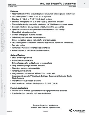
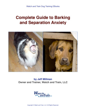
H-Stud Area Separation Wall SystemGA -ASFW 0985*, Two Hour0 ft.Roof StructureH-StudTwo layers:1” PABCO GLASS Shaftliner type X1” PABCORE Shaftliner type XDouble C-Runner, back-to-backO PABCElevation less than 44':aluminum breakawayclips requiredevery 5'ed.SubfloorTop PlatePABCO Gypsum Panel OPABCBase MouldingFloor Joist44 ft.H-StudElevation 44' and greater:additional aluminumbreakaway clips requiredevery 39” OPABCMin. 3/4” Air Spacebetween H-Stud and framingRim joistWood StudBlocking with aluminum breakawayclip every 39” OPABC66 ft.4 of 16FoundationNot to scale. Please refer to specifications for details*Refer to the GA 600 - 2015 Fire Resistance DesignManual for this assembly
Introduction to The PABCO Area SeparationWall System (ASW)The unique design of multifamily, multi-storied townhouses andcondominiums requires special methods of construction that willprovide fire resistance and acoustical separation between dwellingunits. The PABCO H-Stud Area Separation Wall System (ASW) hasbeen developed to meet these critical design criteria.Weighing no more than ten pounds per square foot when erected,the PABCO H-Stud ASW provides a code compliant, efficient,lightweight and low cost solution for separating townhouses, condos,and other multifamily dwelling units by eliminating the necessity ofcostly footers and foundation modifications. An important benefitof the H-Stud ASW is that it may be easily erected directly onto apoured concrete slab by the contractor already on site. Carpenterscan easily install the H-Stud ASW modular system progressivelyonce the framing for one residence is completed and prior to theconstruction of the adjacent unit. The popularity of the non-loadbearing gypsum board H-Stud ASW has grown as contractors andarchitects discover the efficiency, simplicity and cost effectiveness ofthe system.The H-Stud ASW is a two-hour fire-resistance rated assemblyspecifically designed to protect the occupants in attached multiunit residences. Extending continuously from the foundation to,or through the roof, the H-Stud ASW provides sufficient structuralstability under fire conditions to allow collapse of construction oneither side without the collapse of the wall. The H-Stud ASW willalso provide a sound attenuation of 60-64 STC when required andconstructed to PABCO Gypsum’s specifications. The H-Stud ASWcan be constructed up to four stories (66 feet) tall, encompassing allcommon floor-ceiling heights, while providing the highest level offire and sound performance.Shaftliner panels and metal components are easily stacked to allowprogressive construction of the ASW during the framing stages ofthe building.Breakaway aluminum clips allow for the collapse of the structureon the fire-exposed side without collapse of the entire wall orcompromising its structural integrity. The ASW assembly is attachedto each unit’s structural framework using L-Shaped aluminum“breakaway” clips fastened to each side of the ASW’s steel H-Studsand to the structure of each unit. The L-Shaped aluminum clipsconnect each H-Stud on both sides at specified intervals basedupon wall height to keep the area separation in place betweenthe two structures. The L-Shaped aluminum clips are designed tosoften and yield to the heat of the fire at approximately 1,100 F.When one side is exposed to fire, the clips on the exposed fire sidesoften and breakaway allowing the structure on the exposed fireside to collapse. Because temperatures on the unexposed side ofthe ASW will be far below the point at which the clip will soften, thealuminum clips will remain intact allowing the ASW to remain intactand in place, thus protecting the adjacent townhouse.The key component of the H-Stud ASW is a continuous double layerof 1-inch thick, Type X, non-combustible PABCORE Shaftliner orPABCO GLASS Shaftliner panels installed in a continuous assemblyfrom the foundation to the roof, and from the front to the backwall. This construction restricts the spread of fire while maintainingsufficient structural stability under fire conditions to allow collapseof construction on either side without the collapse of the ASW orcompromising structural integrity. Structural support is providedby steel C-Runners and H-Studs. Horizontal structural support isprovided by L-Shaped “breakaway” aluminum slips, as describedin the following section. Depending upon the application, theASW may be extended beyond the roof to form a parapet, or mayterminate at the roof level.5 of 16
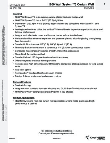
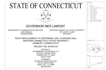
PABCO GA -ASFW 0985H-Stud Area Separation Wall SystemWood Stud Framing GLASS XPABCOaftliner typeShSound batts in stud cavity - optionalPABCO Gypsum panel as requiredPABCO GLASS Shaftliner type X,PABCORE Shaftliner type XSteel H-Studs 24” o.c.RB E CUCMAO FL ypePABC 1/2” TSteel C-Runners (shown back-to-back)Minimum 3/4” clearance betweenASW assembly and wood framingFire blocking as required - not shownFloor joistASS O GLPABCSubflooringAluminum breakaway clipsboth sides, location per specs.Not to scale6 of 16rtlinefahStypeX
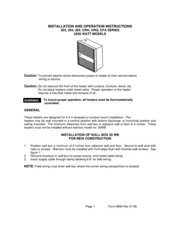
Primary Assembly ComponentsPABCO Gypsum Panels:Steel C-RunnersThe following products are suitable in this system:A C-runner is used at the top and bottom of vertical panels to secure 1”thick PABCO Shaftliner panels and H-studs in ASW assemblies.Central Wall: 1” PABCO GLASS Shaftliner Type X 1” PABCORE Shaftliner Type XFlanking wall: Any PABCO or QuietRock gypsum panelC-Runner is used back-to-back at intermediate floors to provide ajoining system so the ASW assembly can be erected one floor at a time.PABCO GLASS proprietary treated core providingfire resistant, mold-resistant and water-resistantgypsum core, reinforced with glass fibersto increase its resilience.Double Beveled Edge for ease of installationLINERSHAFT SSALGOPABCLength s 1”thicknes1”8’, 9’ 10’24”width & 12’Coated fiberglass mats on both front and back panelsurfaces provide exceptional strength, resisting warping,rippling, buckling and sagging.Steel H-Studs:H-studs are the key framing component, adding structural integrityto Area Separation Wall (ASW) assemblies. The H-studs secure twolayers of 1” thick shaftliner panels between adjacent studs. The 2” -deepH-Studs are inserted into the horizontal C-Runners.2-1/8”Aluminum Breakaway Clips:Aluminum Breakaway Clips are used as an integral part of the ASWassembly as a fuse attachment to the main wall assembly. This clip isdesigned to melt or yield to the high temperatures on the fire sideof the wall allowing the fire engaged wall assembly to collapse whiledetaching itself from the area separation wall. Breakaway clips on thenon-fire side remain intact while holding the ASW in place as a barrierto contain the fire within the unit of origin.2”2”1-½”2”2-½”7 of 16
Primary Assembly ComponentsH-Stud & C-Runner PropertiesH-STUD & C-RUNNER PROPERTIES:ComponentThicknessGaugeSizeDesign ThicknessWidthLength2-1/16” (52.4 mm)10’ (3048 mm)8’ (2438 mm)H-Stud25 ga (18 mil)12’ (3658 mm)0.0188” (0.478 mm)8’ (2438 mm)C-Runner2-1/8” (54 mm)10’ (3048 mm)2” C-Runner2” C-Runnerused as END CAP2” H-Stud2” C-RunnerAluminumBreakaway Clips(not shown)1” x 24“ PABCO GLASS SHAFTLINER Type X , or1” x 24“ PABCORE SHAFTLINER Type X,8 of 16Weight0.44 lbs/ft(0.656 kg/m)0.27 lbs/ft(0.400 kg/m)
ASW ComponentsFasteners & InsulationFASTENERS:Pan Head Screw 1/2” Attaching L-shaped aluminum breakaway clip to H-Stud Attaching horizontal C-Runner track to vertical C-Runnerperimeter tracks Attaching back-back C-Runner tracksType W Drywall Screw 1-1/4” Attaching L-shaped aluminum breakaway clip to wood framingand for attaching gypsum panel to flanking wallDrywall Nail or Screw Attach gypsum panel to wood studs and bearing plates of theadjacent wallSteel Nail 16d Assembly of adjacent wood framingACOUSTIC INSULATION: Acoustic insulation for wall cavity as specifiedFIREBLOCKING: Mineral wool batt fire barrier is used where the ASW membranemeets external walls and roofs9 of 16
H-Stud ASW Features,Uses and LimitationsUSES: The H-Stud ASW is a non-load bearing partition Specifically designed as a 2-hour wall separating units in multifamily construction May be used in buildings up to a total height not to exceed 66 feet The H-stud ASW is designed to be laterally supported with aluminum clips spaced at specified intervals as defined inthe “Design Requirements” section PABCO GLASS Sheathing should be used for all exposed faces of stud framing of Area Separation Walls which protrude beyond theroof or side wallsLIMITATIONS: The H-stud ASW is not intended to be used as a shear wall Penetrations or openings are not permitted in the double shaftliner central wall; the non-fire-resistance rated flanking walls arepermitted to be penetrated as needed to allow for utilities, ducts, or vents in the wall cavity. Do not install insulation in the wall system until the building has been properly closed or dried-in to protect it from the weatherFEATURES: Designed for fast, easy installation that can be erected by carpenter tradesmen The H-stud ASW can be constructed with or without a parapet, depending on roof design and local code requirements Provides continuous fire-resistant membrane from foundation to roof, unbroken by floor or structural members Provides superior sound attenuation The H-stud ASW can be constructed in multifamily projects up to 66 feet in height Weighs less than ten pounds per square foot (10 lb/ft2), resulting in a considerable weight reduction when compared toconcrete blockCODE COMPLIANCE: For Party Walls, the H-Stud ASW must be continuous from the foundation to the underside of the roof sheathing For 2 hour fire walls, the H-Stud ASW must be continuous from the foundation through the roof to form a parapet. It must allow for thecollapse of the construction on the fire side of the wall while remaining intact to protect the structure on its opposite side. In seismic design categories D-F, the H stud ASW may be penetrated by floor sheathing as required by building structural design.10 of 16
Performance TestingFIRE PROTECTION:PABCO GLASS Shaftliner and PABCORE Shaftliner have been independently tested to meet the performance criteria to be classified as Type Xgypsum panels by Underwriters Laboratories in accordance with ASTM C1396 and E119 (UL 263).The fire-resistance rating of an assembly is determined in accordance with ASTM E119 or UL 263 and performed at IAS* certifiedindependent testing laboratories.The PABCO H-Stud ASW system has been extensively tested as a complete system to ensure long-term performance. The substitution ofcomponents in the system could adversely affect the overall performance of the system. Precaution shall be taken that assembly procedures are inaccordance with those of good design practices.Shaftliner TypePABCO GLASS Shaftliner - Type XIndustryStandardCombustibilityASTM 1658Non-CombustiblePABCORE Shaftliner - Type XASTM 1396StructuralNon-loadbearingFire RatedAssembliesWFCi #,07073,19045a, 20011STC Rating60-64RAL-TL07-373SOUND ATTENUATION:Sound transmission is an important consideration as open floor plans, home theaters, and media rooms become more prevalent which increase thesound being transmitted between units through the party walls. The acoustic test data demonstrates the effectiveness of PABCO Gypsum’s AreaSeparation Wall in sound attenuation; thereby, ensuring additional privacy to occupants of adjacent dwellings. STC ratings up to 64 are available.MOLD & MOISTURE RESISTANCE:PABCO GLASS Shaftliner is manufactured using advanced gypsum core and facer chemistries designed with special fungicides to promote long-termmold resistance. PABCO Gypsum was the first in the industry to have completed a long-term mold resistance aging study of the MOLD CURB Plusproduct family. After two years of exposure to varying temperature and humidity conditions, MOLD CURB Plus products continued to inhibit moldgrowth with a perfect score of ten (10) when tested in accordance with ASTM D273.For information regarding system requirements, contact the PABCO Gypsum Technical Services team at 1-800-282-9298.11 of 16
Design RequirementsSYSTEM REQUIREMENTS: Note: the zero (0’) elevation point of an ASW is the top of the wall.Distance is measured downward from the top. When the total height of the ASW is less than forty-four feet (44’),the vertical spacing of the aluminum breakaway clips shall notexceed five feet (5’). Reference WFCI Report #20011 dated August18, 2020. When the total height of the ASW is greater than forty-fourfeet (44’) but less than or equal to sixty-six feet (66’), the verticalspacing of the ASW below the forty-four foot mark (44’) shall notexceed thirty-nine inches (39”). Reference WFCI Report #19045adated August 21, 2019. The maximum height of the PABCO ASW assembly shall notexceed sixty-six feet (66’). When the ASW system is used as an exterior with adjacent framingon only one side, two (2) 1/2” Type S pan head screws are requiredfor the clip attachment. Caulk all gaps between back-to-back C-Tracks with an approvedfire caulking material. There shall be no penetrations allowed in the one-inch shaftlinerpanels.ALUMINUM BREAK-AWAY CLIP REQUIREMENTS: Only use aluminum L-shaped clips to attach the H-stud ASW to theadjacent framing members. In the event of a fire, the break-awayclip is designed to melt, allowing the fire-side framing members tofall away leaving the two layers of 1” PABCO shaftliner intact. L-shaped aluminum clips are attached to each side of every H-stud(2 per stud) with two (2) 1/2” Type S pan head screws throughthe short leg of the clip. Secure the long leg of the clip to woodframing with one (1) 1-1/4” Type W screw. When the total height of the ASW is 44 feet or less, the spacing ofthe breakaway clips is shall not exceed 5 feet on center. When the total height of the ASW is taller than 44 feet and up to amaximum of 66 feet tall, the lateral bracing of the breakaway clipsshall be spaced no more than 39 inches on center. In the event that the H-stud does not align with the adjacentwood framing, insert blocking between wood framing membersand attach aluminum clip to the blocking.12 of 16ACOUSTIC SEALING REQUIREMENTS: Use an approved acoustical sealant and seal all penetrations, theentire perimeter of wall/floor junctions, and the horizontal backto-back C-runners with a minimum 1/4” bead of acoustical sealant. Membrane vertical T junction perimeters shall be sealed forflanking noise using mineral wool insulation between verticalcapping track and the external wall. To maintain acoustic specifications, service penetrations throughwood substrate framing should not be in contact with the ASWmembrane, studs, tracks or clips. All penetrations in flanking wall shall be sealed by applying anacoustical sealant.
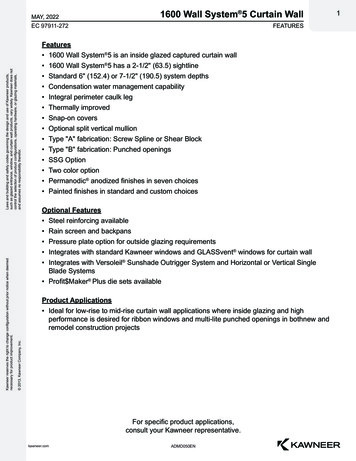
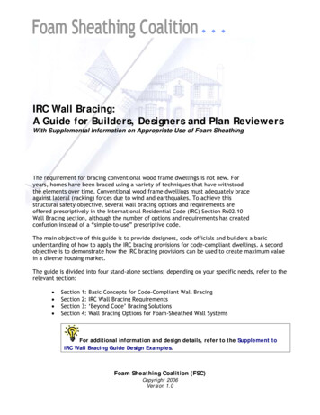
Design DetailsH-Stud Area Separation WallAssembly with two layers of1” PABCO shaftlinerParapet Cap FlashingC-RunnerRoof MembraneRoof SheathingRoof/Ceiling JoistParapet height (As required by local code)C-RunnerRoof SheathingRoof truss memberRoof joist/rafterH-Stud Area Separation Wall Assemblywith two layers of 1” PABCO ShaftlinerSJones 12-09PABCO Gypsumbrand wallboard2x4 top plate & wall framingAlum breakaway clipsGypsum board or mineralwool fire blocking as requiredOptional Sound InsulationPABCO Gypsumbrand wallboard2x4 top plate & wall framingGypsum board or mineralwool fire blocking as requiredAlum breakaway clipsTYPICAL ROOF INTERSECTION DETAILTYPICAL ROOF INTERSECTION PARAPET DETAILElevation ViewElevation ViewDouble C-Runnerback-to-back (horizontal)Alum breakaway clipsMin 3/4” air space2x4 Wood FramingH-StudOptional soundinsulationSubfloorExterior CladdingH-Stud Area Separation WallAssembly with two layers of1” PABCO shaftlinerFloor joistH-Stud Area Separation Wall Assemblywith two layers of 1” PABCO shaftliner(see below for listing of products)Gypsum board or mineralwool fire blocking as requiredC-RunnerExterior SheathingPABCO Gypsumbrand wallboard2x4 top plate &wall framingPABCO Gypsumbrand wallboardOptional sound insulationEXTERIOR WALL INTERSECTION DETAILTYPICAL INTERMEDIATE FLOOR DETAILPlan ViewElevation ViewPABCO Gypsum brand wallboardMin 3/4” air spacePABCO Gypsumbrand wallboardExterior Gypsum SheathingH-StudExterior CladdingExterior Wall FramingOptional soundinsulationSubfloorGypsum board or mineralwool fire blockingas requiredC- RunnerMin 3/4” air spaceFlashing CapH-Stud Area Separation Wall Assemblywith two layers of 1” PABCO shaftliner(see below for listing of products)Floor joistFoundation sillH-Stud Area Separation WallAssembly with two layers of1” PABCO shaftlinerSealant as specifiedC-Runner, fastened to foundationOptional sound insulationAs RequiredTYPICAL FOUNDATION DETAILPROTRUDING EXTERIOR WALL INTERSECTION DETAILElevation ViewPlan View13 of 16
Installation of H-StudArea Separation WallsAPPLICATIONFor structures not located in seismic design categories D-F, H-stud AreaSeparation Walls (ASW) are installed either from above grade, top ofmasonry or concrete footings, and extend, uninterrupted, either to orthrough the roof deck; or from the foundation floor (slab) and extend,uninterrupted. The H-stud ASW is progressively erected one floor at atime with each succeeding floor being stacked on top of the precedingfloor.B. First FloorInstall H-studs and liner panels to a convenient height (max. 2 inchesabove the floor line. Install two thicknesses of 1-inch shaftliner panelsvertically in C-runner with long edges in H-stud. Install H-studs and linerpanels alternately until wall is completed. Cap top of wall section withhorizontal C-runner. Fasten C-runner flanges at all corners both sideswith 1/2-inch Pan Head Type S screws.Each floor height is run from one exterior wall at inside of claddingto the opposite exterior wall inside of cladding creating separatestructures.When exterior cladding is not in place, position 2-inch C-runner endcaps over each end of liner panels and fasten at both sides of eachC-runner at the top and floor of wall using 1/2-inch Pan Head Type Sscrews. When exterior cladding is in place, caulk under the C-Runnerthat will meet the inside of the exterior wall, attach the C-runner tobottom and top of the wall section.For structures located in seismic design categories D-F and whenspecified on plans, H-stud Area Separation wall may be interrupted bycontinuous floor sheathing up to 3/4 inch in thickness (IBC 706.2).INSTALLATIONMin 3/4” air space2x4 Wood FramingH-StudA: Foundation Floor:Position a 2-inch C-runner and securely attach to concrete floor withpower-driven fasteners at both ends and spaced 24-inches O.C. alonglength. Space runner sections 1/4-inch apart. Caulk under runner atfoundation floor with a minimum of 1/4-inch bead of QuietSeal Proacoustical sealant.Exterior CladdingH-Stud Area Separation WallAssembly with two layers of1” PABCO shaftlinerC-RunnerExterior SheathingPABCO Gypsumbrand wallboardPABCO Gypsumbrand wallboardOptional soundinsulationOptional sound insulationEXTERIOR WALL INTERSECTION DETAILSubfloorPlan ViewMin 3/4” air spacePABCO Gypsum brand wallboardH-Stud Area Separation Wall Assemblywith two layers of 1” PABCO shaftliner(see below for listing of products)Floor joistMin 3/4” air spaceExterior Gypsum SheathingH-StudExterior CladdingExterior Wall FramingFoundation sillGypsum board or mineralwool fire blockingas requiredC- RunnerSealant as specifiedC-Runner, fastened to foundationFlashing CapTYPICAL FOUNDATION DETAILElevation ViewH-Stud Area Separation WallAssembly with two layers of1” PABCO shaftlinerNote: C-runner must be positioned a minimum of 3/4-inch fromadjacent framed interior wall that will support the aluminumbreakaway clips.14 of 16Optional sound insulationAs RequiredPROTRUDING EXTERIOR WALL INTERSECTION DETAILPlan View
Installation of H-StudArea Separation WallsC. Intermediate Floors and Bottom of TrussesAttach C-runner for next row of panels to the C-runner below withend joints staggered at least 12 inches. Fasten the C-runners togetherwith double 1/2-inch Pan Head Type S screws at ends and 24-inchesO.C. Attach all H-studs and vertical C-runners to adjacent framing withaluminum breakaway clips at the spacing required for the aluminumbreakaway clip location on the ASW height.Aluminum breakaway clips attaching H-studs and vertical C-runners toadjacent framing on both sides require attachment to the H-stud andvertical C-runner with one 1/2-inch Pan Head Type S screw.Aluminum breakaway clips attaching H-studs and vertical C-runners toadjacent framing on only one side and with exterior exposure on theother side require attachment to the H-stud and C-runner with two1/2-inch Pan Head Type S screws.D. RoofContinue installing H-studs and liner panels for succeeding floor asdescribed. Cut the liner panels and H-studs to roof pitch and length asnecessary to follow the roof pitch. At roof, cap liner panels and H-studswith C-runner. Attach all H-studs to adjacent framing with aluminumbreakaway clips. Clips attaching H-studs and vertical C-runners toadjacent framing on only one side and with exterior exposure on theother side require attachment to each vertical framing member withtwo 1/2-inch Pan Head Type S screws.Roof SheathingC-RunnerRoof truss memberRoof joist/rafterH-Stud Area Separation Wall Assemblywith two layers of 1” PABCO ShaftlinerAluminum breakaway clip attachment to the flanking wall isaccomplished utilizing one 1-1/4” Type W or Type S screw eitherin a vertical orientation to the flanking wall stud or in a horizontalorientation to blocking across the stud cavity.Locate horizontal C-runner joint within 2 inches of the intermediatefloor. Install fire blocking between the solid wall system and adjacentframing at floor lines, bottom of truss line, and any other locationsrequired by the applicable code.SJones 12-09PABCO Gypsumbrand wallboard2x4 top plate & wall framingAlum breakaway clipsGypsum board or mineralwool fire blocking as requiredTYPICAL ROOF INTERSECTION DETAILElevation ViewDouble C-Runnerback-to-back (horizontal)Alum breakaway clipsH-Stud Area Separation WallAssembly with two layers of1” PABCO shaftlinerParapet Cap FlashingOptional soundinsulationSubfloorRoof MembraneC-RunnerRoof/Ceiling JoistParapet height (As required by local code)Roof SheathingFloor joistH-Stud Area Separation Wall Assemblywith two layers of 1” PABCO shaftliner(see below for listing of products)Gypsum board or mineralwool fire blocking as requiredPABCO Gypsumbrand wallboard2x4 top plate &wall framingTYPICAL INTERMEDIATE FLOOR DETAILOptional Sound InsulationPABCO Gypsumbrand wallboard2x4 top plate & wall framingGypsum board or mineralwool fire blocking as requiredAlum breakaway clipsElevation ViewTYPICAL ROOF INTERSECTION PARAPET DETAILElevation View15 of 16Note: When the total height of the ASW exceeds 44 feet but notmore than 66-feet, the vertical spacing between the rows of theL-Shaped aluminum breakaway clips shall not exceed 39 inches.When the total height of the ASW is less than 44 feet, the verticalspacing between the rows of the L-Shaped aluminum breakawayclips shall not exceed 60-inches.
assembly as a fuse attachment to the main wall assembly. This clip is designed to melt or yield to the high temperatures on the fire side of the wall allowing the fire engaged wall assembly to collapse while detaching itself from the area separation wall. Breakaway clips on the non-fire side remain intact while holding the ASW in place as a barrier