Transcription
Pipeline Separation Design andInstallation Reference GuideVersion 9May 2006Publication Number 06-10-029
Pipeline Separation Design & InstallationReference GuideVersion 9Prepared by:Washington State Water Reuse WorkgroupWashington State Department of EcologyWater Quality ProgramWashington State Department of HealthOffice of Environmental Health and SafetyWith Acknowledgment to Primary Authors:Craig L. Riley, WDOH, Water Reclamation & Reuse ProgramandMichael Wilson, WDOH, Office of Drinking WaterJuly 2006Publication Number 06-10-029
You can print or download this document from our Web site at:http://www.ecy.wa.gov/biblio/0610029.htmlFor more information contact:Department of EcologyWater Quality ProgramProgram Development Services SectionP.O. Box 47600Olympia, WA 98504-7600Telephone: 360-407-6401Headquarters (Lacey) leSan ffersonKitsGraysHarbor anThurstonSouthwestLewis360-407-6300PacificWahki ldColumbiaYakimaWallaWallaAsotinKlickitatPersons with a hearing loss can call 711 for Washington Relay Service.Persons with a speech disability can call 877-833-6341.If you need this publication in an alternate format, please call the Water QualityProgram at 360-407-6401. Persons with hearing loss can call 711 for Washington RelayService. Persons with a speech disability can call 877-833-6341.
Table of ContentsEXECUTIVE SUMMARY . 1Introduction. 1Separation Standards. 1Separation-the Final Protection. 2Special Construction Design. 2Conclusions. 2INTRODUCTION . 3Need for this Guidance . 3Background . 3The Need for Pipeline Separation . 4Importance of adequate separation . 4Leakage Damage . 4Public Health and Safety Protection. 5Product Contamination. 6Maintenance & Repair. 7Pipeline Separation Challenges. 8PIPE SEPARATION STANDARDS . 9Elements of Adequate Separation. 9Current Standard . 9Published Separation Criteria . 9Horizontal Separation. 10Vertical Separation . 11Current States’ Standards. 11Engineering and Soils Mechanics Methods. 13Soils Properties Impacts on Critical Trench Depth. 14Parallel Trench Separation vs. Critical Trench Depth. 15MINIMUM PIPE SEPARATION DETERMINATION PROCEDURES . 18General. 18Current Procedures. 18Streamlined Procedures . 18Sidewall Safety Zone . 18Construction / Repair Work Space . 19Minimum Trench Sidewall Cover Depth. 20Horizontal Dimension. 21Minimum Pipe Cover . 21Design Review Conditions . 22Regulatory Approval Requirements. 22Recommendations for Alternatives to Standard Separation for Condition B. 24Typical Construction Details – Condition B. 24Case-by-case Approval Requirements – Condition C . 26Pipeline Separation Design and Installation Reference GuidePage iii
General . 26Approval Requirements. 26Approval Process . 26Suggested Solutions . 27Common Utility Corridor Construction- Condition C. 28Pipeline Crossing – Condition C . 29ENGINEERING DESIGN AND LOCATION APPROACH . 30General Considerations . 30Engineering Judgment . 30Trench Protection . 30Basic Design Approach. 30Multiple Barriers of Protection . 30Record Information Accuracy. 31Trigger Conditions. 31Design Considerations. 31Specific Design Concerns . 32Soil Strengths Data . 32Pipe Leakage. 33Conditions Causing Leaks . 33Pipeline Deterioration . 34Mechanics of Pipe Failure Due to Leaks. 34Allowable Leakage. 35Excavation Site Conditions . 35Repair and Replacement Excavations . 36CONCLUSIONS . 37Table of FiguresFigure 1: Pavement damage due to pipe leak . 4Figure 2: Water line break repair . 5Figure 3: Sewer break . 5Figure 4: Pipeline exposure during repair. 6Figure 5: Waterline exposed by sewer collapse. 7Figure 6: Collateral utility damage due to sewer collapse. 7Figure 7: Standard horizontal pipe separation detail . 10Figure 8: Standard horizontal pipe separation new construction detail of reclaimedwater in developed utility corridor . 10Figure 9: Standard pipe crossing new construction detail - vertical separation . 11Figures 10 and 11: Mechanism for parallel trench collapse . 13Figure 12: Critical trench depth based on soils properties. 15Page ivPipeline Separation Design and Installation Reference Guide
Figure 13: Parallel pipe excavation mechanics. 15Figure 15: Causes of cave-ins (trench surcharges) from Saskatchewan LabourMinistry . 20Figure 16: Pipe separation assessment decision tree . 23Figure 17: Typical benched - common trench construction detail . 25Figure 18: Typical pipe crossing construction detail Condition B separation. 25Figure 19: Condition C utility tunnel. 27Figure 20: Common underground utility corridor . 28Figure 21: Condition C -vertical pipe crossing. 29Figure 22. Lincoln and Spokane county soil types . 33Figure 24: Sand boils resulting from joint failure. 34Figure 25: Typical trench surcharge conditions. 36Figure 26: Field conditions - typical trench surcharge . 36List of TablesTable 1: Utility separation regulations and standards from various states . 12Table 2: Soil Strength Properties . 14Table 3: Estimates of horizontal pipe separation vs. critical trench depth forwater line buried at 3.5 feet. 16Table 4: Estimates of horizontal pipe separation vs. critical trench depth for sanitarysewer line buried at 6.0 feet . 16Table 5: Trench sidewall cover estimate . 21Table 6: Conditions for separation in design with space available. 22Table 7. An Example of soils information from the NRCS Web site. 32Table 8. Allowable leakage based on standard specifications. 35Pipeline Separation Design and Installation Reference GuidePage v
Page viPipeline Separation Design and Installation Reference Guide
Executive SummaryIntroductionAs water reclamation and recycling assumes a larger and more important role in themanagement of water resources, challenges in designing and locating piping systems forthe distribution of reclaimed water are daunting. Existing standards require horizontaland vertical separations between potable water, reclaimed water, storm water and sanitarysewage that are rarely available in developed urban areas. While special constructionpractices are allowed to overcome these obstacles, regulatory approval is required on acase-by-case basis. This process is cumbersome, and increases design and constructioncosts, as well as the completion schedules. The Washington State Department ofEcology and the Department of Health developed this guidance in response to the needfor a streamlined process and to assist utility engineers with pipeline separation designand installation.Pipeline separation is a necessity for protection of public health and safety, property andthe quality of the pipeline contents. Pipeline failure or leaks can result in pipelinecontamination that increases risks public health and safety. Pipelines do not have torupture completely or collapse to cause concern. Even the process of excavating onepipeline to repair a leak creates the risk of complete failure of adjacent pipelines.Separation StandardsThe current pipeline separation standards are based on accumulated field and designexperience, and the Ten State Standards. 1 These standards generally require a minimumhorizontal separation of 10 feet between parallel pipes, and 18 inches of verticalseparation. Many states have adopted these standards as guidance or regulation.In 1968, engineers at Utah State University investigated the effects of trench excavationon separation distances from a buried parallel pipe. Their work resulted in a relationshipbetween the distance from the trench face to the parallel pipe [sidewall thickness, X]necessary to prevent trench wall failure, the critical trench depth [Z], which depends onsoil strength characteristics; the depth of bury [H] of the parallel pipe; and size of theparallel pipe [D]:XH 3 DZAn analysis using this relationship shows that, in some instances, distances less than thestandard horizontal separation distance can be justified. However, this distance is highlydependent on site and soil conditions. In almost all conditions, a minimum sidewallcoverage depth of 2 to 3 feet is necessary to allow sufficient room for maintenance andrepair efforts in the trench, the minimum pipe-to-pipe separation should be 3½ to 4 feet.1Great Lakes Upper Mississippi River Board of State Public Health and Environmental Managers –Recommended Standards of Water Works, Criteria for Water Works, Section 8.6.Pipeline Separation Design & Installation Reference GuidePage 1
Separation-the Final ProtectionPipeline separation provides the final barrier of protection in the multi-barrier approach topipeline protection. Other barriers include: 1) the selection of the pipe material, 2) pipejointing method, 3) pipe bedding procedures and 4) thrust restraint or blocking. Barriersare intended to reduce risks to public health and safety; protect property; preventcontamination of the pipeline contents; protect pipeline customers and prevent collateraldamage to other adjacent facilities. Pipeline separation is the final and most importantbarrier because it remains in place when the other barriers fail.Special Construction DesignMost urbanized areas do not have the space available for standard separation distances.However, special construction methods can be used to assure equivalent levels ofprotection. Special construction methods are necessary whenever the minimumhorizontal and vertical separations cannot be maintained. There are many commonmethods in use today. In selecting the special construction method and design, the designengineer needs to consider design factors such as external forces, impacts of groundwater, and soils-strength characteristics.ConclusionsTo streamline the design and approval process, the agencies have identified three designconditions. Condition A exists when adequate separation distance is available and requires nounusual design considerations. Condition B exists when available horizontal separation is between 4 and 10 feet,and/or available vertical separation is between 6 and 18 inches. For Condition B,special construction methods developed, presented, and approved during theengineering phase of the project and included in the construction drawingsthrough standard details are acceptable. When Condition C exists, available separation is less than 4 feet horizontallyand/or 6 inches vertically. Under Condition C, the agencies must approve specialconstruction on a case-by-case basis.Page 2Pipeline Separation Design & Installation Reference Guide
IntroductionNeed for this GuidanceThe installation of reclaimed water transmission and distribution piping is a major portionof any water reclamation project. The cost of piping and the challenges in fittingadditional buried utilities into crowded utility corridors is often a deciding factor inassessing the project feasibility. Compliance with commonly used standards forhorizontal and vertical pipe separation is proving difficult for nearly every project.Currently, the Department of Health and the Department of Ecology (the agencies) haveallowed variations from these standards on a case-by-case approval basis. This approachis cumbersome and time consuming for the utility and the regulatory agencies. Theagencies recognized the need for a more streamlined, responsive approach.The agencies developed this guidance to streamline the approach to pipeline separation.These guidelines: Provide background information regarding the basis for pipeline separationstandards; Describe the present standards developed from experience and soils mechanics; Describe modes of pipeline failure, the results of pipe failure, and factors thatshould be considered in the design of special conditions, and Provide general design guidance regarding approaches that can be approved bythe regulatory agencies and can be applied without case-by-case, individuallocation approvals.BackgroundUnderground utility pipes provide the core services necessary to urban life. Drinkingwater transmission and distribution, wastewater collection and stormwater drainagesystems now share underground corridors with natural gas, telecommunications,television and electrical power. In many water-limited areas, piped irrigation water linesare common, with reclaimed water being added to the collection of buried utilities. Inorder to allow access for maintenance and repair, utilities must compete for preciousspace in increasingly congested public right-of-ways.The design of underground utilities commonly focuses on the selection of the pipe size toassure manageable pipeline velocities and internal pressure ratings. Other designconcerns include: Pipe materials to address service life and product qualityPipe wall thickness to address internal and external pressures and forcesCorrosion control needs and methodsValves for isolation and drainagePipe jointing methods andThrust restraint and controlPipeline Separation Design & Installation Reference GuidePage 3
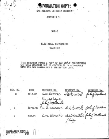
During the design phase, engineers may not focus on the impact of existing, adjacentpipelines. This is because a construction project focuses on isolating, protecting, andaddressing these conditions on a large scale. The original design should also address theneeds during maintenance and repairs. Unfortunately, many pipeline failures occurbecause of the lack of attention to affects on and from existing pipelines.The Need for Pipeline SeparationImportance of adequate separationMany people do not easily understand or recognize the role of pipeline separation inprotecting public health and the environment. However, pipeline contamination canexpose pipeline customers to pollutants. Contamination results from cross-connections,leaks, or complete pipe failure of adjacent underground pipes. Pipeline designers canincrease pipeline reliability through the proper selection of pipe materials, wall thickness,pipe joint systems, thrust restraint systems, pipe bedding, and internal and externalcorrosion control. But ultimately, pipelines corrode, leak, and fail. Adequate separationbetween pipelines provides the final barrier of protection. This minimizes incidentaldamage during the repair of other pipelinesand leakage effects between pipes.Adequate separation also assures sufficientroom to repair leaks and replace brokensections. Finally, separation reduces thepotential for pipeline failure caused by aleak or failure of its neighboring pipeline.Figure 1: Pavement damage due to pipe leakLeakage DamageThe benefits provided by assuring pipelineintegrity are neither readily recognized norFigure 1: Pavement damage due toeasily quantified, until a problem arises.pipe leakUnderground pipelines are out of sight, andout of mind. Commonly, we are aware of problems with these buried pipes only when awater line break shuts water off at home, or a sewer backs up into the basement. Butthese two instances represent inconveniences compared to more common results frompipeline leaks. The following photos show graphic damage created by leaking municipalutilities. Figure 1 shows pavement damage due to a leaking sewer and the consequencesof a water main break in a residential area. Figures 2 and 3 show extensive damagecaused to neighborhood streets by the collapse of a water or sewer line.Page 4Pipeline Separation Design & Installation Reference Guide
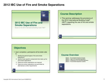
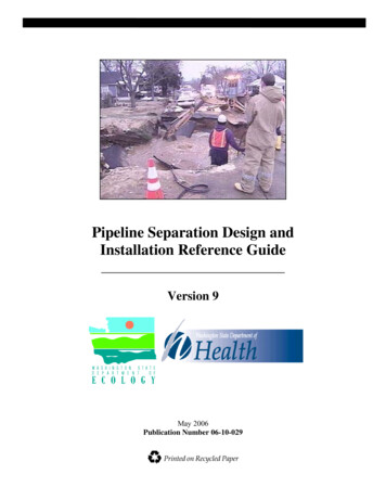
Public Health andSafety ProtectionIn extreme cases, attemptsto repair damage topipelines and the leaksfrom the pipeline canresult in the death ofutility workers. Between1992 and 2001, 542fatalities occurred in theUnited States that wereattributed to trench andexcavation cave-ins. 2However, fatalities arenot limited to utilityworkers alone. A leakingwater main in North CarolinaFigure 2: Water line break repairwas implicated in a mudslide.The mudslide, in turn, causedthe road to collapse into a house, killing a resident.Figure 2: Water line break repairThe risk to public safety is obvious. The extent of property damage and injury can rangefrom slight to catastrophic.All piped utilities sufferdamage, aging andwear. These problemscan allow leakage orinfiltration of groundwater into the pipe.This reduces the qualityof the pipeline contentsand results inadditional costs fordelivery, maintenance,or disposal of the pipecontents.Figure 3: Sewer breakLeaks in potable waterlines can pose asignificant health risk.Figure 3: Sewer breakIn addition, they cancause a loss of revenuefrom a water system that has an investment in the withdrawal, treatment, and distribution.2Centers for Disease Control, Occupational Fatalities During Trenching and Excavation Work --- UnitedStates, 1992—2001, April 23, 2004Pipeline Separation Design & Installation Reference GuidePage 5
Potable distribution and reclaimed water pipelines that operate under pressure and aresubject to customer demands, fluctuating reservoir levels, and pump operation cycles.Hydraulic transients result from pump starts and stops, power failures, main breakssystem operation, or sudden demand changes. This can result in both pressure surges andnegative pressure conditions in the pipe. 3 Leaks may push water out of the pipeline, aswell as pull water, soil, and naturally-occurring microbes back into the pipelines. Thiscan result in contamination of the pipeline contents from micro-organisms and chemicalspresent in the soils surrounding the pipeline. These micro-organisms inoculate the pipeand support microbiologic regrowth. Pathogenic microorganisms are often more prolificin microbiologic regrowth materials.Product ContaminationPipe leaks or breaks can cause contaminants to spread into the environment or from pipeto pipe. Either condition requires pipe repair to maintain product quality. During theexcavation and repair of onepipe, adjacent pipes remain inservice and vulnerable tofailure. Pipes exposed ordamaged during anexcavation repair of anadjacent pipe (Figure 4) oftenrepresent the largest source ofleaks. Pipelines undergoingrepair provide the bestopportunity for contaminantsto enter large openingscreated during the repairprocess.Figure 4: Pipeline exposure during repairContamination of thecontents of undergroundpipelines occurs when the contents of one pipe leaks out and into the soil, and then isdrawn into an adjacent underground pipe. Even small leaks present a contaminantsource. Materials outside the pipe can be drawn into the pipe during pressure surges andvacuum conditions created by hydraulic transients.Figure 4: Pipeline exposure during repairPipe-to-pipe contamination includes: 1) raw sewage leaking into water mains, 2)chemical leakage into reclaimed water mains, 3) raw ground water leaks entering potablepipelines, or 4) contaminated soil being drawn into drinking water systems. Raw sewage,petroleum, or chemical products can leak into the environment causing environmentaldegradation. In the case of natural gas pipelines, leaks can cause explosions.3Gullick, LeChevallier, Svindland, & Friedman, Occurrence of Transient Low and Negative Pressures inDistribution Systems, Journal AWWA, 96:11; November 2004Page 6Pipeline Separation Design & Installation Reference Guide
Collateral DamageAll underground utilities areat risk of a leak or pipefailure. The leak or failurecan severely damage adjacentutilities. The collapse of asewer can cause damage toadjacent utilities, as depictedin Figure 5. This figureshows a worker standing on awater main as the excavationis being dewatered fromanother portion of the hole.Figure 6 shows damage toelectrical, gas, and telephoneutilities.Figure 5: Waterline exposed by sewer collapseMaintenance & RepairAll underground pipelineseventually requiremaintenance and repair. Inan effort to maximize theirwater resources, public watersystems increasingly requireleak detection and correction.Maintenance to repair smallleaks, broken valves, orleaking valve stems requiresexcavation to access the pipeor valves.Figure 5: Waterline exposed by sewer collapseFigure 6: Collateral utility damage due to sewer collapseThe process of locating andexposing undergroundutilities for repair placesother buried utilities inFigure 6: Collateral utility damage due to sewerjeopardy of creating morecollapseleakage from movement ofunsupported, exposed joints, or directly from excavation equipment. Primarycomponents of any maintenance program include 1) ease of access for maintenance and2) repair and protection of workers and adjacent utilities. Proper design decisions easefuture maintenance just as poor design decisions complicate repair or replacement.Pipeline Separation Design & Installation Reference GuidePage 7
Pipeline Separation ChallengesThe protective barrier provided by adequate separation creates additional design andeconomic challenges. With increasing needs, utilities must maximize utility corridors inpublic right-of-ways. Either utilities must widen utility corridors at great expense foradditional land, if available, or remove and relocate an existing utility.Alternatively engineers can devise strategies that will provide an equivalent level ofprotection as that afforded by adequate spacing. This alternative process requires moretime; and stretches completion schedules. However, the benefits include reliability andprotection for public health and safety, with potential savings in construction materialsand effort.Page 8Pipeline Separation Design & Installation Reference Guide
Pipe Separation StandardsElements of Adequate SeparationExcavations are made to install or repair underground pipes. To do so, provide sufficientroom between the trench wall and the pipe on both sides to conduct the work. Theagencies recommend a 12- to 18-inch minimum distance.The design adage holds very true for underground pipelines:All of the really important mistakes are made the first day (during design).The design must focus on maintenance and repair, not just the installation of a newpipeline.Current StandardThe current pipeline separation standards address conditions where potable and nonpotable pipelines run parallel to each other, and where these pipelines cross vertically.The best-known standards are those published in well-known and used utility designguidelines and standards. However, parallel separation requirements follow theprinciples of soil mechanics. The approach based on soil mechanics provides a basis forreduction of horizontal separations under some conditions, and reinforces the need forsignificant separations in others.Published Separation CriteriaThe current standards are based on standard practices developed decades ago andpublished as the Ten State Standards. 4 These standards have been widely adopted andcan now be found in other industry standards and state regulations such as: American Water Works Association - Manual M24- Dual Distribution Systemsand California –Nevada Section AWWA – Guidelines for Distribution ofNonpotable Water Washington State Department of Ecology – Crit
Pipeline Separation Design & Installation Reference Guide Page 1 . Separation-the Final Protection Pipeline separation provides the final barrier of protection in the multi-barrier approach to pipeline protection. Other barrier