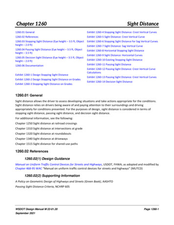
Transcription
Integration of In-Sight with AB PLCs runningRSLogixAuthor: Samantha FrostPublished: August 11, 2017Revision: 1.0Cognex
ContentsCommunicate with a Rockwell ControlLogix PLC . 4Integration with RSLogix 5000 . 4RSLogix 5000, Version 15 , using AOP version 1.28 . 4RSLogix 5000, Version 14 - 16, using Generic or EDS Generated profile: . 5RSLogix 5000, Version 17-19, using Generic or EDS Generated profile: . 6RSLogix 5000, Version 20 , using Generic or EDS Generated profile: . 7EDS Generated Profile or Add-on Profile. 7EDS Generated Profile . 7Add-On Profile . 8Establish the Connection Using the Add-On Profile . 9How to update a previously installed EDS profile, with the new AOP profile . 15How to update a previously AOP (rev 10 ) revision to current revision (rev 12) . 17Get Data from an In-Sight Vision System – 5.x.x Spreadsheet . 19EXAMPLE: Getting 32 bit integer data from an In-Sight vision system . 19EXAMPLE: Getting floating point value data from an In-Sight vision system . 20Send Data To an In-Sight Vision System – 5.x.x Spreadsheet. 22EXAMPLE: Sending 32 bit integer data to an In-Sight Vision System . 22EXAMPLE: Sending floating point value data to an In-Sight vision system . 23Explicit Messages - In-Sight Firmware 5.x.x . 26Example: Change a Job . 26Implicit Job Load Example from RSLogix PLC – 5.x.x . 29Get Data from an In-Sight Vision System - EasyBuilder . 32Send Data to an In-Sight Vision System – EasyBuilder . 34Input/Output Assembly Changes . 36Input/Output Assembly Changes When Upgrading In-Sight 4.x.x Firmware . 36Input/Output Assembly Changes When Migrating to In-Sight Vision Systems Running In-Sight 5.x.x Firmware. 37EtherNet/IP Object Model and Input/Output Assembly Objects - In-Sight 5.x.x Firmware . 38In-Sight Object Model . 38In-Sight Object Model . 39I/O Assembly Data Attribute Format - Input Assemblies - Instance 13 . 39I/O Assembly Data Attribute Format - Output Assemblies - Instance 22 . 43Mapping of I/O Assembly Data Attribute Components . 45Vision Object Attributes . 46Instance Attributes . 46Acquisition Attributes . 48Inspection Results Attributes . 48Behavior of InspectionStatusRegister . 48Job Attributes . 49Vision Object Services . 49Cognex
Common Services . 49Object Specific Services . 49EtherNet/IP Object Model and Input/Output Assembly Objects - In-Sight 4.x.x Firmware . 53EtherNet/IP Communications - In-Sight 4.x.x Firmware . 53In-Sight Object Model . 53Input and Output Assembly Objects . 54I/O Assembly Data Attribute Format - In-Sight Firmware Version 4.10.x . 54Input Assemblies - Instance 12 . 54Output Assemblies - Instance 21 . 57I/O Assembly Data Attribute Format - In-Sight Firmware Version 4.8.0 - 4.9.x . 59Input Assemblies - Instance 12 . 59Output Assemblies - Instance 21 . 61I/O Assembly Data Attribute Format - In-Sight Firmware Version 4.1.0 - 4.7.4 . 63Input Assemblies - Instance 11 . 63Output Assemblies - Instance 21 . 65Mapping of I/O Assembly Data Attribute Components . 66Vision Object Attributes . 67Vision Object Services . 70Common Services . 70Object Specific Services . 70Get Data from an In-Sight Vision System – 4.x.x Spreadsheet . 73EXAMPLE: Getting 32 bit integer data from an In-Sight vision system . 73EXAMPLE: Getting floating point value data from an In-Sight vision system . 74Send Data To an In-Sight Vision System – 4.x.x Spreadsheet. 77EXAMPLE: Sending 32 bit integer data to an In-Sight Vision System . 77EXAMPLE: Sending floating point value data to an In-Sight vision system . 78Explicit Messages – 4.x.x . 80Example: Change a Job . 80Establish the Connection Using the EDS Generated Profile . 84Establish the Connection Using a Generic ETHERNET-MODULE . 88Cognex
Communicate with a Rockwell ControlLogix PLCIn-Sight Communications ReferenceEtherNet/IP CommunicationsThis section describes how to transfer data between an In-Sight vision system and a ControlLogix or CompactLogix PLCon an EtherNet/IP network, using Rockwell RSLogix 5000 software. Integration with RSLogix 5000 EDS Generated Profile or Add-on ProfileIntegration with RSLogix 5000The steps to configure an implicit connection and transfer of data depend on the In-Sight firmware version installed to thevision system, and the version of RSLogix 5000 software.Please note: It is mandatory that you have RSLogix 5000 version 15.00 or later in order to use AOP version 1.28 of the profile. Thisversion of the profile is not compatible with earlier versions of RSLogix 5000. This version provides AOP support to the next generationmodels: IS8000 and IS7000 Gen 2; as well as the legacy In-Sight models.RSLogix 5000, Version 15 , using AOP version 1.28Cognex
RSLogix 5000, Version 14 - 16, using Generic or EDS Generated profile:Cognex
RSLogix 5000, Version 17-19, using Generic or EDS Generated profile:Cognex
RSLogix 5000, Version 20 , using Generic or EDS Generated profile:EDS Generated Profile or Add-on ProfileEDS Generated ProfileElectronic Data Sheets (EDS) are text files used by various network configuration tools to identify In-Sight vision systemson a network. EDS files can be used by any EtherNet/IP device and can be ported across many platforms and vendors.In-Sight EDS files are installed with In-Sight Explorer software in the Factory Protocol Files folder:Cognex
These EDS files are then imported into the appropriate software. For installation information using the EDS or GenericModule, please refer to the ESTABLISH THE CONNECTION USING THE EDS GENERATED PROFILE or theESTABLISH THE CONNECTION USING A GENERIC ETHERNET-MODULE section of this document.Add-On ProfileThe Add-On Profile is functionality added to RSLogix 5000 software and is used for communication with Rockwell PLCs.The user interface for Add-On Profiles provides enumerated access to the configuration and status data with full rangechecking. Data entered is validated to assure that selections made are correct and consistent with the desired setup. TheAdd-On Profile understands the structure of I/O and configuration data and creates tags using names assigned to thedevice in RSLogix 5000. There is complete enumeration of the tag to visibly differentiate the data and all data is availableusing the tag name.The In-Sight Add-On Profile installer is available from the In-Sight support site. Current version is 1.28 and includes all InSight vision systems including the new next generation models (IS8000, IS7500-IS7900 series).Notes: The Add-on Profile installs Major Revision 11 for In-Sight 2000, 57xx, 75xx-79xx, 8xxx, and 9xxx Series Systems,and Major Revision 12 for all legacy models (In-Sight 5xxx,70xx-74xx,10xx Series Systems). Major revision 12 adds TestRun bits to the legacy models. If the Add-On Profile is installed, the EDS generated profile is hidden for In-Sight vision systems with 4.x.x firmwareinstalled. While the latest In-Sight Add-On Profile contains all the contents from previous revisions and will not breakcompatibility with existing applications, whether or not the connection will be established is tied to the MajorRevision field in the Add-On Profile.Cognex
Establish the Connection Using the Add-On ProfileEtherNet/IP Communications - In-Sight 4.x.x Firmware / In-Sight 5.x.x FirmwareIn-Sight Communications ReferenceTo establish an implicit messaging connection with a single ControlLogix PLC using the Add-On Profile:1.Open RSLogix 5000 and load the PLC's project.Note: The PLC must be Offline to add connections in RSLogix 5000.2.Under the I/O Configuration node, select the Ethernet Node under the Ethernet Module, right-click on the icon and select NewModule from the menu:3.When the following dialog appears, select your model of In-Sight Vision System from the list. This option will appear once theAdd-On Profile is installed.Cognex
4.After the selection is made, the configuration dialog for the In-Sight Vision system will be displayed:Cognex
Note: The Time Sync tab is displayed only when connected to an In-Sight 5000, In-Sight 7500-7900 or In-Sight9000 series vision systems.The following fields need to be configured:5. Name: This is the name given to the In-Sight vision system; the tags created in RSLogix 5000 will be based on thisname. It is recommended that the In-Sight vision system's name be used, to maintain consistency. IP Address: The IP address of the In-Sight vision system. Host Name: This setting is optional; only use this setting if there is a Domain Name Server (DNS) on the network.After accepting the general communication parameters, the next step in the configuration process is displayed in the figurebelow:Cognex
The following fields can be configured: Requested Packet Interval (RPI): This field specifies the Requested Packet Interval (RPI), which defines theamount of time (in milliseconds) between data exchanges across an implicit messaging connection.Note: For best results, the RPI time should be set to no more than half the time between when theIn-Sight vision system completes the job execution and when the PLC requires the data. Major Fault On Controller If Connection Fails While in Run Mode: This option will cause the controller togenerate a major fault when the connection fails. Inhibit Module: Checking this box prevents the PLC from attempting to establish a connection with an In-Sightvision system.Note: If the In-Sight vision system appears to be stuck in "Standby" mode, then inhibiting and reenabling the module can cause the module to become operational again.6)After adding the module to ControlLogix, the I/O tree should appear as follows:7)RSLogix 5000 will then create tags that map to the In-Sight vision system's Input and Output Data, based on the namegiven to the device. InSight Top:I Scheduled Input: The table below represents the data that is sent FROM the In-Sight vision systemto the PLC:Cognex
InSight Top:O Scheduled Output: The table below represents the data sent TO the In-Sight vision system fromthe EtherNet/IP client (ControlLogix):Cognex
Cognex
How to update a previously installed EDS profile, with the new AOP profileEtherNet/IP Communications - 5.x.x FirmwareIn-Sight Communications ReferenceThese steps assume a vision system has already been setup in your RSLogix project with the EDS file.Notes: 1)Install AOP 1.28a)2)5)This will remove the controller tags but it will leave the tags in the ladder as Undefined tag, and the rungs will be markedwith a red X or e (for error).Add the cameras back using the AOP Module and use the same names and IP addresses of the deleted cameras.a)4)Make note of the EDS generated profile camera names & IP addresses that you want to replace with the AOP cameramodule.Delete the EDS cameras from the module list (you will get tag errors)a)3)When using Rockwell RSLogix Studio 5000 version 14 and earlier, an Allen-Bradley Generic ETHERNET-MODULE must beused. The EDS generated profile must also be used since the new AOP (1.28) requires RSLogix 15 or greater. Reference thecharts in the “Integration with RSLogix” section of this document for install guidance.The icon will be the grey Rockwell Automation moduleDelete the copy rungs needed for the EDS generated camerasa)These are no longer needed since the AOP creates module defined types and controller tags as structured data under theController- Controller tags. These rungs were needed to move the unstructured data under the MainProgram, to structuredcontroller tags.b)With the AOP, when the data is sent from In-Sight to the PLC, this data will appear in the input controller tags for the InSight: In-Sight Name:I. And when data is sent from the PLC to In-Sight, the data should be placed in the output controllertags for the In-Sight: In-Sight Name: OSearch and replace all the cameras tags to update them to the new tag names.a)Additionally, a search and replace of the structured tags that the EDS data was copied into by the rungs. These referencesshould be replaced with the new camera names: In-Sight Name:I and In-Sight Name: O .The EDS installation ladder would have used the insight11 in and insight11 out tags that were created from the rungimport. These tags use the user-defined types that map out the signals for control and status. Since these rungs are nolonger needed, search for those tags and replace with the In-Sight Name:I and In-Sight Name:O. The status andcontrol parts of the tag and signal names are there already.b)Below is an example of systems setup with the EDS profile and the AOP profile. Note the systems setup with the EDS profilehave a 1 appended at the end of each tag. While the systems setup with the AOP do not.Cognex
Cognex
How to update a previously AOP (rev 10 ) revision to current revision (rev 12)EtherNet/IP Communications - 4.x.x FirmwareIn-Sight Communications ReferenceThis section assumes AOP 1.26 has been used. This installs revision 10. To use the new AOP version 1.28 (installs revision 12), followthe steps below. Also make note of the assembly IO changes between revisions. These are highlighted in the Assembly I/O Changessection of this document.The following steps can be taken to use the new AOP:1)Install the AOP version 1.28.2)Open the camera module properties and press the Change . button.3)Select the current AOP revision (revision 12 for camera models running 4.x.x).4)Correct any errors in tags.a.There are updates to the IO assembly and you may see errors in the rungs using the tags highlighted in red below.The camera input/output tags for version 10 are on the left.The camera input/output tags for version 12 are on the right.Tag name changes are highlighted in red boxes on revision 12.Cognex
Cognex
Get Data from an In-Sight Vision System – 5.x.x SpreadsheetEtherNet/IP Communications - In-Sight 5.x.x FirmwareIn-Sight Communications ReferenceIn order to get data from the In-Sight Explorer Spreadsheet to a ControlLogix PLC, the data must be pushed into the EtherNet/IPstack by using the WriteResultsBuffer function. This function takes a buffer of data created by the FormatOutputBuffer function andwrites it to the data area in the In-Sight vision system's EtherNet/IP Input Assembly (input to the network). This data is thentransferred to the PLC during the next RPI cycle.The EtherNet/IP buffer writes to this data area are queued, meaning that they do not happen during Spreadsheet execution, but as aseparate event slightly after the execution of the Spreadsheet. This means that there is a small window of time during which aninspection will be complete, but a new buffer write will not have resolved.It is important to use the ResultsValid bit to decide when to read data to prevent subtle intermittent timing issues in your PLC logicthat can arise from this setup, as ResultsValid will only become high when data are ready to read, and not before. EXAMPLE: Getting 32 bit integer data from an In-Sight vision system EXAMPLE: Getting floating point value data from an In-Sight vision systemEXAMPLE: Getting 32 bit integer data from an In-Sight vision systemThe following steps explain how to format the data that will be sent from an In-Sight vision system to a ControlLogix PLC.1.2.3.4.5.6.7.8.9.10.To begin, using In-Sight Explorer, create a new job.From the Palette's Snippets tab, add these two Snippets to the spreadsheet: Acquisition AcqCounter and Math & Logic Random.Open the AcquireImage cell and set the Trigger parameter to Continuous.Right-click an empty cell and select Insert Function. From the left-side of the screen, expand the Input/Output category anddouble-click on the FormatOutputBuffer function to insert it into the spreadsheet.From the FormatOutputBuffer dialog, click on the Add button. This will initiate the cell selection mode; select the "Scaledrandom number" cell of the Random snippet.From the FormatOutputBuffer dialog, use the Data Type pull-down menu to change the Data Type to 32 bit integer.From the FormatOutputBuffer dialog, click on the Add button again. This will initiate cell selection mode; select the count cellof the AcqCounter snippet.Close the FormatOutputBuffer by clicking the OK button.Right-click an empty cell and select Insert Function. From the left-side of the screen, expand the Input/Output category, clickon the Network subcategory and double-click on the WriteResultsBuffer function to insert it into the spreadsheet.Set the WriteResultsBuffer function's Protocol parameter to EtherNet/IP, and the Buffer parameter as a cell reference to the justcreated FormatOutputBufferdata structure. Set a value of 3 in the WriteResultsBuffer Results Code parameter. (Orreference any cell with integer data)11.Place the In-Sight vision system Online.12.The data should now be displayed in the Controller - Controller Tags node of RSLogix 5000.Note: The RSLogix Monitor Tags tab must be selected in order to display the data values.Cognex
EXAMPLE: Getting floating point value data from an In-Sight vision systemIf a floating point or a mix of data types needs to be sent, in ControlLogix create a User Defined Type. Copy the floating point datainto the newly created User Defined Type from the In-Sight vision system's input tag.The steps below illustrate how to copy two cells as floating point values:1.Place the In-Sight vision system Offline.2.Open the previously created FormatOutputBuffer function.3.From the FormatOutputBuffer dialog, use the Data Type pull-down menu to change the Data Type from 32 bit integer to 32bit floating point.Note: Matching the Data Type being used by the vision system is not necessarily required. The bits are copied verbatim fromthe vision system's output buffers in the order that they appear in FormatOutputBuffer or the Format Outputs tab, regardlessof the data type used to receive the buffer in the PLC.4.Place the In-Sight vision system back Online.5.In RSLogix, go into Offline mode.6.Within RSLogix, right-click on the Data Types - User-Defined folder and select New Data Type from the menu.7.Give the new data type a descriptive name and add two floating point values to the Members: list.8.Next, add a new tag to the project's Controller Tags, using the user defined data type.Cognex
9.Finally, add a COP instruction to the MainRoutine ladder logic program, which will copy the data from theInSight Top:I.InspectionResults[0] tag to the InSight Top Input tag.Note: The Length field is the number of the input structures that should be copied to the output. In this case, the inputstructures are 32-bit floating point values, so the COP command copies 64 bits from the vision system's output buffer into theuser-defined type in the PLC. If we were using 16-bit integer types (INT)in the PLC's receiving buffers, then we would haveused a length of 4 to get the same 64 bits, and if we were using 8-bit integer types (SINT), then we would have used alength of 8 to copy all 64 bits.10.After this program has been downloaded to the ControlLogix PLC, the data from the Random and Acquisition Counter In-SightExplorer spreadsheet cells will now appear in the InSight Top Input tag in the floating point format:Cognex
Send Data To an In-Sight Vision System – 5.x.x SpreadsheetEtherNet/IP Communications - In-Sight 5.x.x FirmwareIn-Sight Communications ReferenceIn order to send data from the ControlLogix PLC to the In-Sight Explorer spreadsheet, the data must be pulled from the EtherNet/IPstack by using the ReadUserDataBuffer function. This function takes the data format created within the FormatInputBuffer functionand reads the data from the data area of the EtherNet/IP Output Assembly (output from the network), and formats this data into theIn-Sight Explorer Spreadsheet. This data is received from the PLC every RPI cycle; the corresponding Spreadsheet data is updatedonly when the Spreadsheet executes.EXAMPLE: Sending 32 bit integer data to an In-Sight Vision SystemFor this example, create a new job within In-Sight Explorer, then perform the following steps to configure the data that will bereceived by the ControlLogix PLC.1)Open the AcquireImage cell and set the Trigger parameter to Continuous.2)Right-click an empty cell and select Insert Function. From the left-side of the screen, expand the Input/Output category anddouble-click on the FormatInputBuffer function to insert it into the spreadsheet.3)From the FormatInputBuffer dialog, click on the Add button and add two 32-bit integers to the list.4)Close the FormatInputBuffer by clicking the OK button.5)Right-click an empty cell and select Insert Function. From the left-side of the screen, expand the Input/Output category, clickon the Network subcategory and double-click on the ReadUserDataBuffer function to insert it into the Spreadsheet.6)Set the ReadUserDataBuffer function's Protocol parameter to EtherNet/IP, and the Buffer parameter as a cell reference to thejust created FormatOutputBufferdata structure.7)The Data Access functions will automatically be added to the spreadsheet based on the fields added to theFormatOutputBuffer function.8)Place the In-Sight vision system in Online mode.9)Within RSLogix 5000, open the Controller Tags dialog and change the value of the InSight Top:O.UserData[0] andInSight Top:O.UserData[1] tags.10) Determine if the User Data handshaking is needed. If the User Data Bypass is enabled, the exchange of data will mimic thatof the 4.xx cameras. If the User Data Bypass is not enabled (default state), this new bit will add additional handshaking toCognex
the data exchange between PLC and In-Sight. Additional steps will be neede
Cognex These EDS files are then imported into the appropriate software. For installation information using the EDS or Generic Module, please refer to the ESTABLISH THE CONNECTION USING THE EDS GENERATED PROFILE or the ESTABLISH THE CONNECTION USING A GENERIC ETHERNET-MODULE section of this document. Add-On Profile
