Transcription
TM3 monitoringinstallation andusers manualunit
contentsintroduction2analogue names25product description2configuration page2634-20mA sensor configuration page27product certification3self test configuration page29related documents3temperature sensor configuration page30physical description4disabled alarms configuration page32uncleared alarms configuration page33inventory7general configuration page34additional parts8camera configuration page35SNMP configuration page36security configuration page37log out page38document overviewinstallation9install the TM3 unit9power cord, network cableand GSM antenna connections10sensor connection11front panel functions39temp39self test40disable/enable all alarms41clock41temperature sensors11flood sensors11dry contacts114-20mA sensors12enter41relay connection12GSM sms data access4213view data45initial configurationbefore the unit is used operationally the followinghome page46minimum configuration is required13alarm log47set the time and date13graph view48connecting laptop to TM314camera view49GSM configuration15SNMP50ethernet/internet configuration (first time)17configuration19maintenance51contact configuration page20trouble shooting52alarm profile configuration page21clean the TM3 monitoring unit53dry contact alarm configuration page22analogue alarms configuration page24disposal53specifications54transmission selection241
introductionproduct descriptionThe TM3 Monitoring Unit is a generic environmental monitoring system, capable of interfacing to varioussensors and communicating sensor status on Ethernet (web based), GSM and SNMP. Sensors which can beconnected include NTC temperature sensors, flood sensors, dry contacts and third party 4-20mA sensors.The unit can be configured through the web interface and by SMS. Temperature Thresholds can alsobe configured on the front panel keypad interface. Sensor levels and thresholds, alarm descriptions,alarm profiles, contact details and communication data are configurable on the unit.The TM3 Unit is capable of logging alarms and analogue sampled data which can be viewed from theweb interface. Images from a network enabled camera can be viewed on the web interface. Twoonboard relays for controlling external devices and a 12Vdc and 18Vdc power supplies are available onthe unit. The unit has battery backup capability during mains power failure. Onboard SD card saves allprogrammed information. In the event of a unit failing the SD card is removed from the faulty unit andinserted into a new unit and the TM3 is ready to monitor.2
document overviewThe TM3 Unit Installation and Users Manual describes how to install a TM3 Monitoring Unit, how sensors are connected and configurationof the sensor inputs is performed. It also describes maintenance and fault finding. After performing the installation and configurationprocedures as set out in this document, the TM3 Unit is ready for installation specific configuration and operational environmentalmonitoring.product certificationThe TM3 Unit CE certification is pending. The following IEC specifications are applicable to the TM3 Monitoring Unit:nElectrical Fast Transients (EFT)IEC 61000-4-4nElectrostatic Discharge (ESD)IEC 61000-4-2nSurgesIEC 61000-4-5nRadiated SusceptibilityIEC 801-3nVoltage Dips and InterruptionsIEC 61000-4-11nConducted SusceptibilityIEC 61000-4-6nEmissions and HarmonicsIEC 61000-3-3 and IEC 61000-3-2nGeneral Products Safety Directive2001/95/ECnRoHS Compliance2002/95/ECrelated documentsUnless otherwise noted, the following documentation and software is available on the CD provided with the device or on the applicableproduct page on the RT Systems website www.rtsystems.co.zanInstallation and Users ManualnICASA Approval CertificatenGSM Module Certification DatanIP Set SoftwarenIOD’snTM3 Base Station Programming Software.Refer to the software help file for installation and users instructions.nSD card default configuration filesnSNMP mib file3
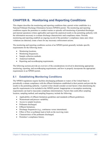
physical descriptionfront panel612345789 10 11itemdescription1TRMGSM Transmit IndicatorThis is a red LED and will light up during GSM transmission and reception.2TEMPTemperature setup select keyThe temperature sensor thresholds and calibration settings are configured when selecting the TEMP key.Press twice in succession to calibrate the sensors.3Down keyThe down key is used to scroll through menus and decrement numerical values during system configurationand setup.4Right keyThe right key is used to move the cursor to the right during system configuration and setup.5ENTEREnter keyPress Enter to enter the telemetry menu where raw input data can be viewed. The Enter key is also used tosave setup data.4
itemdescription6LCDLiquid Crystal DisplayThe LCD displays all the system data.7GSMn8SELF TESTSelf test select keyBy selecting the Self Test key the unit performs a sequence of tests to determine its own health status.GSM Status IndicatorFlashing once every second – Initialising, not registered on the GSM network.n Flashing once every three seconds – Registered on GSM network.9Up keyThe up key is used to scroll through menus and increment numerical values during system configurationand setup10Left key/Clock/CancelThis is a multifunction key. Press to set up the time and date of the unit. When in a setup menu this keycan be used to move the cursor to the left. This key is also used to cancel menu selections when in a menuselect mode.11DISABLEALLALARMSDisable All AlarmsBy selecting this key all alarms will be disabled. To enable alarms select key or unit enables alarms afterone hour. This will be indicated on the LCD and on the Web interface.5
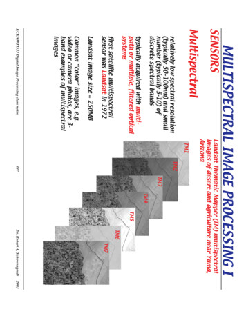
back panel1234567891011 12 13itemdescription1GSM AntennaConnectorSMA connector for GSM antenna connection.2VOLTAGE OUTPUTProvides one 18V dc, 50mA voltage output for sensor supply voltage.34-20mA InputsThree 4-20mA inputs available for connecting third party sensors.4TemperatureSensor InputsFour inputs available to connect NTC temperature sensors.5FLOOD SENSORINPUTSTwo inputs available for multiple flood sensors in series terminated with a 10kΩ end of line resistor.6Voltage OutputProvide two 12V dc, 200mA voltage outputs for sensor supply voltage.7DRY CONTACTINPUTSEight dry contacts available for dry contacts.8DRY CONTACTINPUTSSeven dry contacts available for dry contacts.9RELAY OUTPUTSUsed for relay controlled external devices.1010/100 Base-TNetwork PortProvides for a 10/100 Base-T network connection with status and link LEDs indicate network traffic.11On/OffOn/Off switch for unit power.12Inlet FuseProvides for input power protection. See maintenance parts for fuse rating.13AC Line InletProvides for the input power connection. See specification on page 54 for voltage information.6
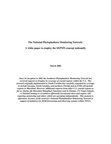
inventoryInspect the contents of the package to ensure that the parts included match those shown below. Reportmissing or damaged contents to RT Systems or your TM3 reseller. However, if damage was due to shipping,immediately report the damage to the shipping agent.itemdescriptionThe shipping and packaging materials are recyclable. Please save them for later use or dispose of themappropriately.TM3 monitoring unitThe main component in the shipment.utility cdThe utility CD contains the Installation and Users Manual, Certification data, TM3 Base Station Programming Software, ip Set Software,snmp MIB file, oid’s, sd card default configuration files and Freeware SNMP browser link.SD cardThe SD Card is installed on the TM3 Monitoring Unit and contains default configuration data.10 position terminal blockIncluded are six terminal blocks for interfacing to the terminals at the back of the TM3 Monitoring Unit.GSM antennaA GSM antenna is supplied. The antenna has a magnetic base for easy fitment.power cord:A mains lead with BS 546 plug is supplied.cross-over ethernet cableThe supplied cross-over Ethernet cable is used for interface directly to a laptop.installation packThe supplied installation pack consists of 10 cable ties, 4 screws for mounting TM3 unit on 19” rack and 6 cable tie mounts.7
additional partsAdditional parts are not supplied with the TM3 Unit. These parts are installation specific and are suppliedby the installer.NTC temperature sensorsAnalogue sensor.humidity/temperature sensor (dry contact)Alerts are activated by means of a contact closing/opening when threshold is reached.flood sensorThe water detector will detect potential flood risks in the server room caused by condensation water form air cons or burstwater pipes.4-20mA current transducerMonitor the amperage of ups and generator distribution boards.4-20mA humidity sensorMonitor humidity in server rooms. High humidity – condensation. Low humidity – static.smoke detector sensorAn important addition to security and safety. These smoke detectors are easy to install and configure. The smoke detector must bemounted on the ceiling for maximum smoke detection.door contact sensorMonitor and be alerted when there is access to server rooms, server cabinets.8
installationinstall the TM3 UnitThe TM3 Monitoring Unit is enclosed in a standard 1U 19” enclosure. Install the unit in the front of the rack, which requires one U ofrack space. When installing the TM3 Monitoring Unit, take into consideration the following:symboldescriptionCCaution: Only connect approved devices to ports on the unit as directed in this manual. Plugging in otherdevices may result in equipment damage.NNote: Install the appliance in an environment compatible with the maximum ambient temperature specifiedin “Specifications” on page 54. Units installed in a closed or multi-unit rack assembly can experience agreater operating ambient temperature than the ambient room temperature.NNote: Install the unit in a way that allows sufficient airflow for safe operation.NNote: When you install the unit in the rack, be sure that you do not create a hazardous condition due touneven mechanical loading. For example, do not use the unit as a shelf.NNote: When you install the GSM antenna, be sure that you have good GSM reception. Install the antennapreferably outside the rack assembly for improved reception.9
power cord, network cable and GSM antenna connectionssymbolCCdescriptionCaution: Before you energise the appliance, review the electrical specifications to avoid overloadingthe circuit.Caution: Make sure you properly ground the appliance by plugging the power cord directly into a wall outletor by verifying the ground path if using a power strip.NNote: The power cord provided is to be used only with the TM3 Monitoring Unit.NNote: Only use the GSM antenna provided with the unit.1.Connect the supplied power cord to the AC Line Inlet of the unit.2.Secure the power cord to the power cord retainer bracket using the tie wraps.3.Connect the supplied network cable to the 10/100 Base-T Network Port on the unit.4.Plug the power cord into a power source.5.Connect the GSM antenna to the unit.10
sensor connectiontemperature sensorsConnect the NTC temperature sensor at the back of the unit marked “Temperature Sensors” to any one of the available four inputs. DryContact Temperature sensors can be connected to any one of the 15 inputs marked “Dry Contact Inputs”. To extend the temperaturesensor use standard CAT-5 cable to a maximum distance of 100 metres. Tie the cable to the cable support at the back of the unit usingthe tie wraps provided.flood sensorsUse the supplied flood sensors on the TM3 Monitoring Unit. Connect the flood sensor at the back of the unit marked “Flood Sensors”to any one of the available two inputs. The flood sensors can be extended using standard CAT-5 cable to a maximum distance of 100metres. Tie the cable to the cable support at the back of the unit using the tie wraps provided. Flood sensors to be installed with the10kΩ end of line resistor terminated on the last flood sensor.connect toTM3 unit10Ωdry contactsThird party dry contacts can be used (Normally Open or Normally Closed contact). Connect the dry contacts at the back of the unitmarked “Dry Contacts” to any one of 15 available inputs. Extend the dry contact using standard CAT-5 cable to a maximum distance of100 metres. Tie the cable to the cable support at the back of the unit using the tie wraps provided. The dry contacts can be configuredactive open (HIGH) or active closed (LOW). Follow third party installation instructions provided with the dry contacts.11
4-20mA sensorsUse third party 4-20mA sensors as per specification on page 8. Connect the 4-20mA sensors at the back of the unit marked “4-20mASensors” to any one of three available inputs. Extend the 4-20mA sensors using standard CAT-5 cable to a maximum distance asspecified by the sensor manufacturer. Tie the cable to the cable support at the back of the unit using the tie wraps provided. The TM3Monitoring Unit implements a 100Ω sense resistor to which the 4-20mA sensor connects. At the back of the unit two 12V (200mA) powersupply and one 18V (50mA) power supply outputs are available for sensor power supply. Ensure that the 4-20mA sensor does notoverload the power supply. Two wire and three wire sensor connections are shown below. 4-20ma sensors that are available: Humidity,Temperature, Amperage.two wire sensor connection4-20mA sensorsthree wire sensor connection4-20mA sensorsTM3 unitTM3 unit V power in- V power in GND S signal output V power in S signal outputrelay connectionConnect the cable that is connected to external device to the back of the unit to either one of the two relays. Common/Normally Openor Common/Normally Closed contacts can be used. Relays can be Energised/De-energised by either going into the Dry Contacts AlarmsConfiguration Page and selecting 0 De-energise or 1 Energise or by sending an SMS command to the TM3 Unit.12
initial configurationbefore the unit is used operationally the following minimum configuration is requiredsymbolNdescriptionnSet the unit’s time and datenConnect TM3 to LaptopnConfigure the GSM settingsnConfigure the Ethernet/networkPower up the unit and wait 1 minute before starting with initial configuration. An “I” in the right hand corner of the LCD indicates theunit is busy initialising. “I” will only disappear when the GSM configuration is complete. The default display is displayed on the LCD. Thedata available on the default display is the Time, Day and Temperature value of Temperature Sensor 1.set the time and dateTo set the unit’s time and date press the “Left/Clock Key” on the front panel of the unit. The data available for configuration is the Time,Day of week and Date. Use the Right and Left keys to move the cursor to the data field which has to be adjusted. By pressing the Up orDown key the data field will be incremented or decremented. After all data fields have been adjusted to the correct values, press theEnter key to store the data.13
After the Enter key has been pressed the following display will appear for a couple of seconds.connecting laptop to TM3nConnect crossover cable from TM3 to LaptopnSet the local area connection on Laptop–Internet protocol (TCP/IP) Properties–General–Use the following IP address: 192.168.0.49 Access the web interface by opening Internet Explorer (IE) and enter http://192.168.0.50 in the address bar, the login page of theunit will be displayed on IE. Enter the default administrator user name “admin” and password “admin”, note that all letters arelower case, the user name and password are case sensitive. The Home Page will appear when logged in.14
GSM configurationThe GSM needs to be configured before the unit will be able to send SMSs. This is done on the web interface by performing the followingsteps:symbolNdescriptionThe GSM configuration should be done before the Sim Card is installed in the unit.From the Home Page of the TM3 Monitoring Unit select Configuration, now select GSM from the options and the following GSM setuppage will be displayed:15
The following data can be configured:nCellular Number Enter the cellular number of the Sim card installed in the unit. Internationalnumber format is required. The correct number is required for the unit’s Self Testfunction to operate correctly.nGSM Service Centre Number (SMSC) Enter the service provider Service Centre Number in this field. Obtain numbernPIN Code Enter the Sim card PIN code. If Sim does not have a PIN then refer to thenPUK Code Enter the Sim card PUK code.from the cellular service provider.section below ‘Steps to add Pin to Sim card.’Select Save to store data on the unit after all fields have been configured. Select Cancel and follow the prompted instructions to revertback to the previous settings. The data will not be stored in this case.Insert the Sim card in the unit. Refer to the maintenance section of this manual for the location of the Sim card holder. Wait a few secondsand the GSM status indicator will start flashing once every 3 seconds and the “I” on the display will disappear.symbolNdescriptionIf the “I” does not disappear then unit must be switched off and then on to complete initialisation.Steps to add PIN to Sim card (Steps 2 to 4 may vary on certain Cellphones):1. Insert Sim into a cellphone2. Go to ‘Security’ settings.3. Select ‘Phone and Sim card’4. Select ‘Pin code request’5. Change to ‘On’6. You will be prompted for a PIN number.7. Enter a unique Pin, Pin will be rejected 3 times.8. You will be prompted for the PUK number.9. Enter the PUK number.10. Enter Unique Pin.11. Pin will be accepted, then follow the ‘GSM Configuration’ steps.16
ethernet/internet configuration (first time)The unit is shipped with the following default network settings:nIP Address192.168.0.50nGateway Address192.168.0.2nSub-Net Mask255.255.255.0nDNS IP Address192.168.0.4The Ethernet data can be changed and configured on the web interface. Select Configuration on the Home Page icon bar, now selectEthernet/Internet and the Ethernet/Internet Configuration page appears.17
The following data can be configured:nE-mail address 1 E-mail address 1 to where alarm messages can be sent. A tick box is available,when ticked this address will be used.nE-mail address 2 E-mail address 2 to where alarm messages can be sent. A tick box is available,when ticked this address will be used.nTransmit alarms to e-mail addresses Enable the checkbox to send alarm message to the e-mail addresses providedabove.nIP Address of TM3 Configure a static IP Address for the TM3 Monitoring Unit.nSubnet MasknIP Address of gateway Configure the network gateway IP Address.nDNS Server IP Address Configure the network DNS server IP Address.nMAC Address of TM3nFrom e-mail address Configure the unit’s e-mail address.nOutgoing mail server Configure the outgoing mail server address.nOutgoing Mail Server (SMTP) Authentication Click on checkbox if SMTP server requires authentication.nSMTP User nameSMTP User name.nSMTP PasswordSMTP Password.Configure the network subnet mask.A read-only field which displays the Mac Address of the unitSelect Save to store data on the unit after all fields have been configured. Select Cancel and follow the prompted instructions to revertback to the previous settings. The data will not be stored in this case.The IP Set utility on the CD can be used to set the TM3’s IP Address. Enter the unit’s Mac Address and the required TM3 IP Address.symbolNdescriptionWhile the majority of SNMP servers do not require authentication, in a case where it is required pleaseprovide the information as described in the outgoing mail server (SMTP) authentication section. If you areusing the Microsoft Exhange E-mail Service, a mail box needs to be created and the log in credentialsentered onto the system.18
configurationThis section describes generic configuration procedures which are required to configure a unit for a specific operational installation.Configuring a unit entails the following basic steps by selecting the appropriate TABS on the web interface TAB bar:Set up your contacts in the Contacts Configuration Page. Here you specify all the numbers andnames to which SMSs have to be sent.Step 1:ContactsSet up the alarm profiles in the Alarm Profile Configuration Page. This specifies which alarms haveto be sent to which contacts.Step 2:Alarm ProfilesStep 3:Dry Contact AlarmsStep 4:Analogue AlarmsSet up the dry contact alarms in the Dry Contact Alarm Configuration Page. Alarm descriptions,active levels and Enable/Disable settings are done on this page.Set up the analogue alarms in the Analogue Alarms Configuration Page. Analogue alarms includethe temperature, flood, 4-20mA sensors and TM power supply. Transmission selection, Alarmdescriptions, and Enable/Disable settings are done on this page.Miscellaneous configuration is performed in the Configuration Page and include the following:n 4-20mA Sensors where threshold levels are configuredn GSM (refer to Initial Configuration GSM Configuration on page 15)n Ethernet/Internet (refer to Initial Configuration Ethernet/Internet Configuration on page 17)n Self Test where a weekly self test is scheduledn Temperature Sensors, where the temperature sensor sampling period, hysteresis levels andthreshold levels are configuredStep 5:n Disabled Alarms, where a daily disabled alarms report is scheduledConfiguration Pagen Uncleared Alarms, where a daily uncleared alarms report is scheduledn General, the Site identification name is specified as well as the dry contact alarm delay time.The software version of the unit is displayed in this pagen Camera. A network enabled camera can be viewed on the web – interface. In this page thecamera IP Address is configured. Change the administrator and user passwords in this pagen SNMP configuration is done on this page where access parameters are enteredChange the administrator and user passwords and configure the auto logout on this page.Step 6:Security19
contact configuration pageFrom the Home Page of the TM3 Monitoring Unit select Contact Configuration Page. The following page will be displayed:The following data can be configured:nCellular Phone Number Enter the cellular number of the contacts to which SMSs are required to besent. International number format is required.nDetailed name description Enter the name of the contact. This can be a person or machine.Select Save to store data on the unit after all fields have been configured. Select Cancel and follow the prompted instructions to revertback to the previous settings. The data will not be stored in this case.20
alarm profile configuration pageFrom the Home Page of the TM3 Monitoring Unit select the Alarm Profile Configuration Page. The alarm profiles are configurable onthree separate pages ie, Alarm Profile Matrix 1, Alarm Profile Matrix 2 and Alarm Profile Matrix 3. Each has to be configured in order tocomplete the profiles for all the alarms. The following page will be displayed for matrix 2:The following selections can be done:nAlarm tick boxes A particular alarm can be directed to send an SMS to a specific contact whenticked in the corresponding Alarm Input vs Contact tick box.nSelect/Deselect All To select or deselect All Alarms. Note that this selection is only applicable to thealarms displayed on this page.Select Save to store data on the unit after all fields have been configured. Select Cancel and follow the prompted instructions to revertback to the previous settings. The data will not be stored in this case.21
dry contact alarm configuration pageFrom the Home Page of the TM3 Monitoring Unit select the Dry Contact Configuration Page. The following page will be displayed:22
The following data can be configured:nName TagThis is the alarm name which uniquely identifies the alarm.nHI Description Tag This is the alarm fault condition if Active HI is selected. If Active LOW is selectedthe normal condition description of the alarm is entered.nHI SMS Tick Box Tick this box if an SMS is required when this alarm condition is activated.nLO Description Tag This is the alarm fault condition if Active LOW is selected. If Active HI is selectedthe normal condition description of the alarm is entered.nLO SMS Tick Box Tick this box if an SMS is required when this alarm condition is activated.nAlarm Message for LCD Enter the alarm condition description for the LCD.nActive HI/LOW Select the Active HI alarm condition for Dry Contacts which are normally closed,activating the alarm when open. Select Active LOW alarm condition for DryContacts which are normally open, activating the alarm when closed.nEnable/DisableThree selection options are available: 1 EnableNotification of alarm will be made on the LCD and SMSif selected. 0 DisableNotification of alarm is disabled. The daily Disabled Alarmsreport will include all disabled alarms. P Permanently DisabledNotification of alarm is disabled and is notincluded in the Disabled Alarms report.Select Save to store data on the unit after all fields have been configured. Select Cancel and follow the prompted instructions to revertback to the previous settings. The data will not be stored in this case.23
analogue alarms configuration pagetransmission selectionFrom the Home Page of the TM3 Monitoring Unit select Analogue Alarms Configuration Page and Transmission Selection. The followingpage will be displayed:The following data can be configured:nSMS tick boxSelect which alarms will be sent by SMS.Select Save to store data on the unit after all fields have been configured. Select Cancel and follow the prompted instructions to revertback to the previous settings. The data will not be stored in this case.24
analogue namesFrom the Home Page of the TM3 Monitoring Unit select Analogue Alarms Configuration Page and Analogue Names. The following pagewill be displayed:The following data can be configured:nName TagThis is the alarm name which uniquely identifies the alarm.nLCD IdentifierEnter the alarm condition description for the LCD.nEnable/DisableThree selection options are available: 1 EnableNotification of alarm will be made on the LCD and SMSif selected. 0 DisableNotification of alarm is disabled. The daily Disabled Alarmsreport will include all disabled alarms. P Permanently DisabledNotification of alarm is disabled and is notincluded in the Disabled Alarms report.Select Save to store data on the unit after all fields have been configured. Select Cancel and follow the prompted instructions to revertback to the previous settings. The data will not be stored in this case.25
configuration pageThe following configuration options are available on the Configuration Page:n4-20mA Sensor 1n4-20mA Sensor 2n4-20mA Sensor 3nGSMnEthernet/InternetnSelf TestnTemperature SensorsnDisabled AlarmsnUncleared AlarmsnGeneralnCameranSNMP26
4-20mA sensor configuration pageFrom the Home Page of the TM3 Monitoring Unit select Configuration Page. Select one of the three 4-20mA Sensor options forconfiguration. The following page will be displayed. (The configuration procedure for all three sensors is identical.)27
The following data can be configured:n4mA signal (zero level value) Enter the zero level of the connected sensor, corresponding to its 4mA level, inthis field.n20mA signal (full scale level value) Enter the full scale level of the connected sensor, corresponding to its20mA level, in this field.nUnits of measure Enter the connected sensor units of measure, ie %RH for a humidity sensor.nAlarm activation level The level at which an alarm needs to be activated is entered in this field.nHysteresis Enter the hysteresis level, below or above (depending on the activation direction)the activation level at which the alarm will be de-activated. (Ref. note 1, pg 31)nAlarm activation direction Select the alarm activation direction, ie increasing values or decreasing values.nSampling period Select the sampling period at which the sensor is sampled for display on theGraph View. A maximum of 1 440 sample points are stored.Select Save to store data on the unit after all fields have been configured. Select Cancel and follow the prompted instructions to revertback to the previous settings. The data will not be stored in this case.28
self test configuration pageFrom the Home Page of the TM3 Monitoring Unit select Configuration Page and from the option list select Self Test. The following pagewill be displayed:The following data can be configured:nDay of scheduled weekly Self Test Select the day of the week when the scheduled self test will be performed.nTime for scheduled weekly Self Test Enter the time of day when the scheduled self test will be performed.nSend Self Test Result to e-mail addresses Tick this box if the self test result is required to be e-mailed to the addressesconfigured in the Ethernet/Internet Configuration Page.Select Save to store data on the unit after all fields have been configured. Select Cancel and follow the prompted instructions to revertback to the previous settings. The data will not be stored in this case.29
temperature sensor configuration pageFrom the Home Page of the TM3 Monitoring Unit select Configuration Page and from the option list select Temperature Sensors. Thefollowing page will be displayed:The following data can be configured:nNon-critical Temperature sensor hysteresis (T1) Enter the hysteresis1 level below the Non-critical Threshold level, at which thealarm will be de-activated.nCritical Temperature sensor hysteresis (T2) Enter the hysteresis1 level below the Critical Threshold level, at which the alarmwill be de-activated.nSampling Period Select the sampling period at which the sensor is sampled for display on theGraph View. A maximum of 1440 sample points are stored.nNon-critical Threshold Enter the Non-critical Threshold level for the temperature sensor at which thealarm will be activated.nCritical Threshold Enter the Critical Threshold level for the temperature sensor at which the alarmwill be activated.30
Note 1: Hysteresis represents the di
The TM3 Monitoring Unit is a generic environmental monitoring system, capable of interfacing to various sensors and communicating sensor status on Ethernet (web based), GSM and SNMP. Sensors which can be connected include NTC temperature sensors, flood sensors, dry contacts and third party 4-20mA sensors. introduction