Transcription
DATA SHEETVGC10www.cobotsonline.co.uk · 44 (0) 1325 31337 · sales@cobotsonline.co.uk
1. Datasheet1.1. VGC10General PropertiesMinimumTypicalMaximumUnit5%-80 -6*[kg]--13.2 *[lb]-1015[kg]-2033.1[lb]Vacuum cups1-7[pcs.]Gripping time-0.35-[s]Releasing time-0.20-[s]Vacuum pumpIntegrated, electric BLDCDust filtersIntegrated 50µm, field replaceableIP ClassificationIP54Dimensions101 x 100 x 100[mm]3.97 x 3.94 x 3.94[inch]0.814[kg]1.79[lb]VacuumAir flowWith default attachmentsPayloadWith customized attachmentsWeight* By using three 40mm cups. More info in the table Number of Cups needed for non-porousmaterials depending on payload and vacuum.Operating ConditionsMinimumTypicalMaximumUnitPower supply20.42428.8[V]Current consumption506001500[mA]Operating temperature0-50[ C]32-122[ F]Relative humidity (non-condensing)0-95[%]Calculated operation life30 000--[Hours]2 ChannelsThe VGC10 has 4 holes to use fittings with vacuum cups or blinding screws as needed. It alsohas lines which show the holes that are communicated together. This is useful when usingchannels A and B independently for vacuum.www.cobotsonline.co.uk · 44 (0) 1325 31337 · sales@cobotsonline.co.uk
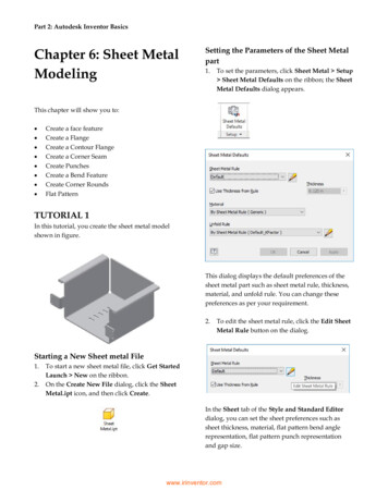
Adaptor PlateThe VGC10 comes with an Adaptor Plate which provides extra flexibility to locate the vacuumcups inconfigurations.The Adaptor Plate has 7 holes to use fittings with vacuum cups or blinding screws as needed.It also has lines which show the holes that are communicated together. This is useful whenusing channel A and B independently for vacuum.The Adaptor Plate can be placed inpositions by rotating it 90º. Having as referencethe letters A and B written on the gripper housing, the Adaptor Plate can be placed toseparate both channels or to communicate them. If the Adaptor Plate is placed as in picturebelow on the left, both channels will be separated, and they can be used independently orcombined. If the Adaptor Plate is placed as in picture below on the right, both channels will becommunicated and a higher air flow can be achieved, although both channels will have to beused combined.www.cobotsonline.co.uk · 44 (0) 1325 31337 · sales@cobotsonline.co.uk
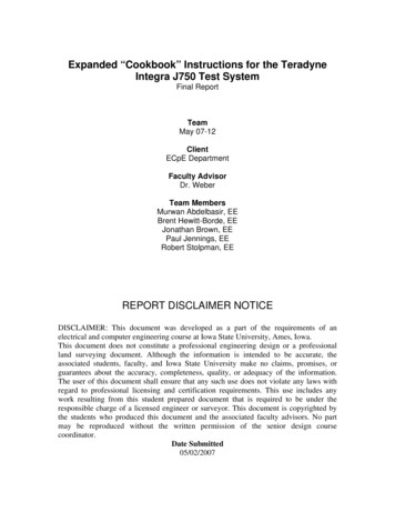
To mount the Adaptor Plate simply remove the 4 fittings or blinding screws from the gripper,place the Adaptor Plate by choosing the right angle according to the desired configuration,and tighten the 4 screws with 4 Nm tighten torque.NOTE:Please, note that the O-Ring in the Adaptor Plate is not glued therefore it canbe pulled out. If that happens simply put it back in place and the gripper willwork as before.Extension PipeThe Extension Pipe provides an extra length of 50 mm to reach narrow spaces.www.cobotsonline.co.uk · 44 (0) 1325 31337 · sales@cobotsonline.co.uk
iNOTE:Remember to use the Adaptor Plate rotated to achieve a higher air flow whenusing both channels together.The Extension Pipe can be mounted in any of the holes by simply screwing it in and adding afitting on top as shown in the image below.Belowmounting configurations with the provided attachments are shown.www.cobotsonline.co.uk · 44 (0) 1325 31337 · sales@cobotsonline.co.uk
Customized Adaptor Plates and Push-in FittingsThe design of the VGC10 is meant to facilitate the users to make their own adaptor plates tocreatekinds of configurations. The dimensions needed to create a customizedadaptor plate are shown in the image below.The Push-in Fittings are used to attach 4 mm vacuum tubes to create customizedconfiguration that required remote vacuum. In most cases, this size is enough for generatingthe needed vacuum from the pump in the gripper.www.cobotsonline.co.uk · 44 (0) 1325 31337 · sales@cobotsonline.co.uk
The commercial name of the Push-in Fittings is Fitting QSM-G1/8-4-I-R in case some moreunits need to be purchased.An example of a customized configuration with a homemade adaptor plate and remotevacuum is shown below.The image below shows how the push-in fittings and the normal fittings are communicated.www.cobotsonline.co.uk · 44 (0) 1325 31337 · sales@cobotsonline.co.uk
PayloadThe lifting capacity of the VG grippers depends primarily on the following parameters: Vacuum cupsVacuumAir flowVacuum CupsChoosing the right vacuum cups for your application is essential. The VG grippers come withcommon 15, 30 and 40 mm silicone vacuum cups (see table below) which are good for hardand flat surfaces, but not good for uneven surfaces and it might leave microscopic traces ofsilicone on the workpiece which can cause issues with some types of painting processesafterwards.ImageExternal Diameter [mm]Internal Diameter [mm]Gripping Area [mm2]1562930162004024450For non-porous materials, the OnRobot suction cups are highly recommended. Some of themost common non-porous materials are listed below: CompositesGlassHigh density cardboardHigh density paperMetalsPlasticPorous materials with a sealed surfaceVarnished woodIn an ideal case, working with non-porous material workpieces where there are no air flowgoing through the workpiece, the table below shows the number of cups and the cup sizeneeded depending on the payload (workpiece mass) and the vacuum used.Number of Cups needed for non-porous materials depending on payload and vacuum :www.cobotsonline.co.uk · 44 (0) 1325 31337 · sales@cobotsonline.co.uk
15 mmPayload (kg)iVacuum (kPa)30 mm40 mmVacuum (kPa)Vacuum 13-118614-------14-128715-------15-1397NOTE:To use more than 7 (15mm), 4 (30mm) or 3 (40mm) vacuum cups with theVGC10 a customized adaptor plate is needed.The table above is created with the following formula that equalizes the lifting force with thepayload considering 1.5G of acceleration.www.cobotsonline.co.uk · 44 (0) 1325 31337 · sales@cobotsonline.co.uk
AmountCups * AreaCup[mm] 14700Payload [kg]Vacuum [kPa]It is often a good idea to use more vacuum cups than needed, to accommodate for vibrations,leaks and other unexpected conditions. However, the more vacuum cups, the more airleakage (air flow) is expected and the more air is moved in a grip resulting in longer grippingtimes.When using porous materials, the vacuum that can be achieve by using the OnRobot suctioncups will depend on the material itself and will be between the range stated in thespecifications. Some of the most common non-porous materials are listed below: FabricsFoamFoam with open cellsLow density cardboardLow density paperPerforated materialsUntreated woodSee the table below with general recommendations, in case other suction cups are neededfor specific materials.Workpiece surfaceVacuum cup shapeVacuum cup materialHard and flatNormal or dual lipSilicone or NBRSoft plastic or plastic bagSpecial plastic bag typeSpecial plastic bag typeHard but curved or unevenThin dual lipSilicone or soft NBRTo be painted afterwardsAny typeNBR onlyVarying heights1.5 or more bevelsAny typeiNOTE:It is recommended to consult a vacuum cup specialist to find the optimalvacuum cup where the standard types are insu cient.Suction Cups for Foil and Bags Ø25This suction cup improves the vacuum gripper’s ability to pick and place workpieces withsurface of foil, thin paper, and plastic bags during irregular and angular arm movement.www.cobotsonline.co.uk · 44 (0) 1325 31337 · sales@cobotsonline.co.uk
25 mmNumber of Cups12Surface34kgFoil0.831.071.431.57Thin paper1.081.712.233.21Foil - round shape1.282.323.324.25Plastic bag0.320.540.630.74The vacuum cup is silicone rubber compliant with the USA Food and Drug Administration(FDA).Using this vacuum cup reduces the wrinkles made on thin workpieces (film, vinyl, and so on)during absorption:.This vacuum cup is an accessory and need to be purchased separately. To purchase thevacuum cup, contact the vendor from where the VGx gripper has been purchased. Suction Cups for foil and bags Ø25 - PN 105922Fittings and Blind Screwsthe fittings. It might be a bitIt is possible to change suction cups simply by pulling themchallenging to remove the 15 mm Diameter vacuum cups. As suggestion try to stretch thesilicon to one of the sides and then pull it out.www.cobotsonline.co.uk · 44 (0) 1325 31337 · sales@cobotsonline.co.uk
Unused holes can be blinded using a blind screw, and each fitting can be changed to atype to match the desired suction cup. The fittings and the blinding screws aremounted or dismounted by screwing (2Nm tightening torque) or unscrewing them with theprovided 3 mm Allen key.The thread size is the commonly used G1/8”; allowing for standard fittings, blinders andextenders to be fitted directly to the VG grippers.VacuumVacuum is defined as the percentage of absolute vacuum achieved relative to atmosphericpressure, i.e.:% vacuum BarkPainHgTypically used for0%0.00rel.0.00rel.0.0rel.No vacuum / No lifting capacity1.01 abs.101.3 abs. 29.9 abs.0.20rel.20.3rel.20%40%6.0rel.0.81 abs. 81.1 abs.23.9 abs.0.41rel.12.0rel.40.5rel.Cardboard and thin plasticsLight workpieces and long suction cup life span0.61 abs. 60.8 abs. 18.0 abs.60%0.61rel.60.8rel.18.0rel.Heavy workpieces and strongly secured grips0.41 abs. 40.5 abs. 12.0 abs.80%0.81rel.81.1rel.23.9rel.Max. vacuum. Not recommended0.20 abs. 20.3 abs. 6.0 abs.The vacuum in kPa setting is the target vacuum. The pump will run at full speed until thetarget vacuum is achieved, and then run at a lower speed necessary to maintain the targetvacuum.The pressure in the atmosphere varies with weather, temperature and altitude. The VGgrippers automatically compensate for altitudes up to 2km, where the pressure is about 80%of sea level.Air FlowAir flow is the amount of air that must be pumped to maintain the target vacuum. A completelytight system will not have any air flow, whereas real life applications have some smaller airsources:leakages from twowww.cobotsonline.co.uk · 44 (0) 1325 31337 · sales@cobotsonline.co.uk
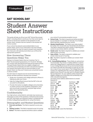
Leaking vacuum cup lipsLeaking workpiecesThe smallest leak under a vacuum cup can be hard to find (see picture below).Leaking workpieces can be even harder to identify. Things that look completely tight mightnot be tight at all. A typical example is coarse cardboard boxes. The thin outer layer is oftenover it (see figure below).requiring a lot of air flow to create a pressureTherefore, the users must be aware of the following: VG grippers are not suitable for most uncoated, coarse cardboard boxes.Extra attention must be paid to leakages, e.g. vacuum cup shape and surface roughnessThe air flow capability of a VG grippers is shown in the graph below:www.cobotsonline.co.uk · 44 (0) 1325 31337 · sales@cobotsonline.co.uk
iNOTE:The easiest way to check if a cardboard box is su ciently tight is simply to testit using the VG grippers.A high vacuum percentage setting does not give a higher lifting capacity oncorrugated cardboard. In fact, a lower setting is recommended, e.g. 20%.A low vacuum setting results in less air flow and less friction below the vacuumcups. This means VG gripper filters and vacuum cups will last longer.1.2. VGC10All dimensions are in mm and [inches].14 www.cobotsonline.co.uk· 44 (0) 1325 31337 · sales@cobotsonline.co.uk
All dimensions are in mm and [inches].www.cobotsonline.co.uk · 44 (0) 1325 31337 · sales@cobotsonline.co.uk
A high vacuum percentage setting does not give a higher lifting capacity on corrugated cardboard. In fact, a lower setting is recommended, e.g. 20%. A low vacuum setting results in less air flow and less friction below the vacuum cups. This means VG gripper filters and vacuum cups will last longer. 1.2. VGC10 All dimensions are in mm and .