Transcription
Programming GuideVLT Condition-based MonitoringVLT FC Series
Programming Guide VLT Condition-based MonitoringContentsContents1 Before you begin41.1Introduction to the Programming Guide41.2Reading the parameter table52 Overview of Condition-based monitoring72.1Introduction to Condition-based Monitoring72.2Alarms and Warnings83 Parameter Descriptions103.1Parameter Group 45 -** Condition-based Monitoring103.2Parameter Group 47 -** CBM Baseline Data164 Appendix4.14.24.320Motor Stator Windings204.1.1Alarm 510, Motor Stator Winding Alarm204.1.2Warning 510, Motor Stator Winding Warning 1204.1.3Warning 500, Motor Stator Winding Warning 220Vibration Monitoring204.2.1Alarm 512, Vibration Monitoring Alarm204.2.2Warning 512, Vibration Monitoring Warning 1214.2.3Warning 502, Vibration Monitoring Warning 221Load Envelope214.3.1Alarm 511, Load Envelope Alarm214.3.2Warning 511, Load Envelope Warning 1214.3.3Warning 501, Load Envelope Warning 221Danfoss A/S 2019.07AU310741645108en-000101 / 3
Programming Guide VLT Condition-based MonitoringBefore you begin1 Before you begin1.1 Introduction to the Programming GuideIntroductionThis chapter describes the purpose of the programming guide, intended audience, disclaimer, safety conventions, and additionalresources.Purpose of this Programming GuideThis programming guide provides information on working with Condition-based monitoring parameters on the VLT FC series.It provides an overview of parameters and value ranges for operating the drive. Installation and operating instructions are not in scopeof the programming guide.Intended AudienceThe intended audience of the programming guide is trained personnel, automation engineers, and programmers with experience inoperating with parameters and with basic knowledge of Danfoss AC drives.DisclaimerThis publication contains information proprietary to Danfoss. By accepting and using this manual, the user agrees that the informationcontained in this is used solely for operating equipment from Danfoss, or equipment from other vendors if such equipment is intendedfor communication with Danfoss equipment over a serial communication link. This publication is protected under the Copyright lawsof Denmark and most other countries.Danfoss does not warrant that a software program produced according to the guidelines provided in this manual functions properly inevery physical, hardware, or software environment.Although Danfoss has tested and reviewed the documentation within this manual, Danfoss makes no warranty or representation,neither expressed nor implied, concerning this documentation, including its quality, performance, or fitness for a particular purpose.In no event shall Danfoss be liable for direct, indirect, special, incidental, or consequential damages arising out of the use, or theinability to use information contained in this manual, even if advised of the possibility of such damages. In particular, Danfoss is notresponsible for any costs, including but not limited to those incurred as a result of lost profits or revenue, loss or damage of equipment,loss of computer programs, loss of data, the costs to substitute these, or any claims by third parties.Danfoss reserves the right to revise this publication at any time and to make changes to its contents without prior notice or anyobligation to notify former or present users of such revisions or changes.Safety SymbolsThe following symbols are used in this manual:DANGERIndicates a hazardous situation which, if not avoided, will result in death or serious injury.WARNINGIndicates a hazardous situation which, if not avoided, could result in death or serious injury.4 Danfoss A/S 2019.07AU310741645108en-000101 / 130R0901
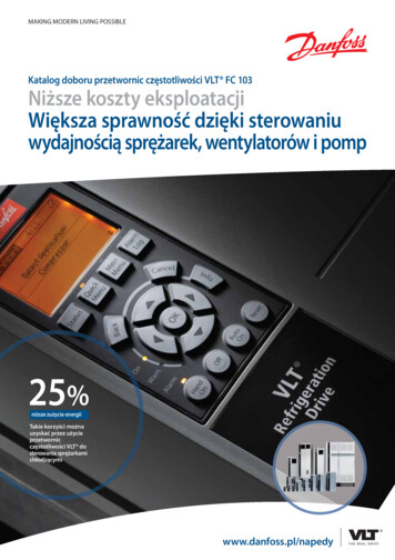
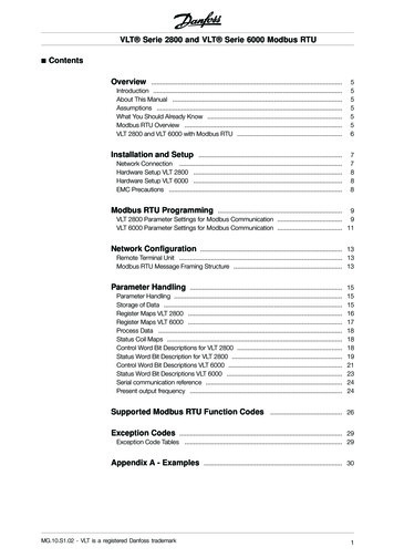
Before you beginProgramming Guide VLT Condition-based MonitoringCAUTIONIndicates a hazardous situation which, if not avoided, could result in minor or moderate injury.NOTICEIndicates information considered important, but not hazard-related (for example, messages relating to property damage).Additional ResourcesAdditional resources are available to help you understand related information.Technical documentation for various product options is available via the Danfoss home page in the Service and Support/Documentation section.1.2 Reading the parameter table235614Illustration 1:e30bu346.10This programming guide includes parameter and options tables. These descriptions explain how to read the parameter and optionstables.Parameter Table1 indicates the value set in factory.2 indicates whether the parameter type is option or range.3 indicates the manner of parameter set-ups. All setups means that the parameter can be set individually in each of the 4 setups. Forexample, 1 single parameter can have 4 different data values. 1 setup indicates that the data value is the same in all setups.4 refers to the conversion index. Parameter values are transferred as whole numbers only. Conversion factors are therefore used totransfer decimals. If a value is transferred as 100 and a conversion index of -1, the real value is 10.0.5 indicates the different data types for the parameters.6 indicates whether the parameter value can be changed while the frequency converter is in operation. False indicates that thefrequency converter must be stopped before a change can be made.Table 1: Conversion TableConversion indexConversion factor1001753600000Danfoss A/S 2019.07AU310741645108en-000101 / 130R0901 5
Programming Guide VLT Condition-based MonitoringConversion indexConversion 01Before you beginTable 2: Data typeData typeDescriptionType2Integer 8Int83Integer 16Int164Integer 32Int325Unsigned 8Uint86Unsigned 16Uint167Unsigned 32Uint329Visible stringVisStr33Normalized value 2 bytesN235Bit sequence of 16 boolean variablesV254Time difference w/o dateTimD6 Danfoss A/S 2019.07AU310741645108en-000101 / 130R0901
Programming Guide VLT Condition-based MonitoringOverview of Condition-based monitoring2 Overview of Condition-based monitoring2.1 Introduction to Condition-based MonitoringCondition-based monitoring in Danfoss VLT drives is launched as a factory-flashed licensed firmware, embedded within the Danfossdrive. The Condition-based monitoring requires control card MK II.NOTICEThe Condition-based monitoring software must be purchased separately along with the drive from the factory.Benefits of installing the condition-based monitoring firmware are as follows: Reduces unexpected downtime Optimizes drive or motor working conditions Eliminates unexpected halts in productionCondition-based monitoring enables to regularly check the condition and performance of the machine when the drive is in service anddetects mechanical, motor, or application failures in advance. Corrective actions can be performed before the process or application isimpacted. Alarms or warnings are triggered in the drive to notify customers or service technicians. Some of the corrective actionsinclude replacement of faulty motors or bearings and ensuring the motor is running within optimal conditions.Following are the monitoring capabilities introduced: Motor stator winding monitoring: During monitoring, inter-turn short circuit or unbalance in the motor winding is detected inadvance. Damages caused by motor stator winding isolation occurs over a period of time. When more winding turns are impacted,the overcurrent protection is activated due to extensive heating and stops the motor. Vibration monitoring: With the help of external sensors, the drive can monitor vibration levels in a motor. Vibrations affect motorcontrol and can lead to motor failure. During monitoring, early detection of motor misalignment is detected and wear and tear ofmechanical parts are identified earlier.NOTICEISO10816 standard provides guidance for evaluating vibration severity for machines operating within 10-200 Hz offrequency range. The standard shall be complied with before commissioning of vibration monitoring function. Load envelope: Mechanical load of an application is monitored by comparing current load curve with expected load curve basedon data gathered during commissioning. During monitoring, overload and under-load deviations which occur in applications aredetected.To begin condition-based monitoring a baseline must be generated. During this activity, the system captures motor stator winding,vibration monitoring, and load envelope speed points for each baseline. The user can define the duration, minimum and maximumspeed for baseline generation. During baseline generation, 20 speed points are captured. To secure a speed point, a provision isprovided to select a bandwidth of /- 2% for each speed point. The first and last speed point is captured based on the definedminimum and maximum speed respectively.When speed points are not captured properly, baseline generation fails. For more monitoring over a duration, a new baseline has to begenerated.The baseline serves as a reference for threshold limits. Using parameters, the user can select the type of baseline measurement.Danfoss A/S 2019.07AU310741645108en-000101 / 130R0901 7
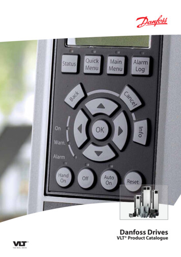
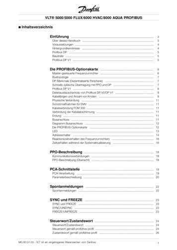
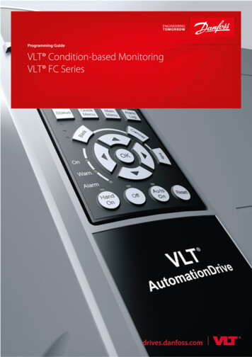
Programming Guide VLT Condition-based MonitoringOverview of Condition-based monitoring Baseline Run: The drive controls the motor speed and monitors required values to derive a baseline. The drive creates a speedprofile for baseline measurement. The drive interrupts the application during baseline run to operate on the speed profile createdfor baseline measurement. The duration for baseline calculation can be specified. Online Baseline: When the application begins operation, the drive measures the baseline automatically. The drive measures thebaseline without interfering with the motor control. Danfoss Drives recommend running the application for 24 hours to 1 week foreffective measurement of baseline data.BaselineComputationIllustration nt stages of condition-based monitoring are as shown.Condition-based monitoring stagesBaseline Computation: During the initial stage, baselines for different types of condition-based monitoring are computed, based onthe type of baseline mode selected by the user.Threshold Calculation: Once the baseline is computed, the thresholds for warnings (stage 1 and stage 2) and alarms are computedbased on the warning or alarm mode. The threshold and mode are set via parameters.Monitoring: After the thresholds are calculated, condition-based monitoring begins. Alarms and warnings are triggered duringdeviations to notify customers.2.2 Alarms and WarningsIn condition-based monitoring, for each feature, the user can define activation stages for warnings and alarms. The interpretation ofalarm and warning color codes are as follows:Green: No alarms are indicated. Condition-based monitoring operations continue.Yellow: First indication of warning stage 1 alarm is visible. Warning stage 1 faults is also shown as warning S1. Notification to users toplan for maintenance operations. In this stage, condition-based monitoring operations continue.Orange: Clear indication of warning stage 2 alarm is visible. Warning stage 2 faults is also shown as warning S2. Notification to users toact as soon as possible before the fault becomes critical.WarningNo Faults Stage 1FaultWarningStage 2FaultCriticalFaulte30bu345.10Red: A critical alarm has occurred and condition-based monitoring operations has stopped.ThresholdTimeIllustration 3:Alarm and Warning Stages8 Danfoss A/S 2019.07AU310741645108en-000101 / 130R0901
Programming Guide VLT Condition-based MonitoringOverview of Condition-based monitoringFor more information, see 4.1 Motor Stator Windings, 4.2 Vibration Monitoring, and 4.3 Load Envelope.Danfoss A/S 2019.07AU310741645108en-000101 / 130R0901 9
Parameter DescriptionsProgramming Guide VLT Condition-based Monitoring3 Parameter Descriptions3.1 Parameter Group 45 -** Condition-based MonitoringIn this parameter group, you can enable condition-based monitoring, define units, baseline computation, input sources, view baselinestatus, and progress.Parameter 45-00: FunctionTable 3: Parameter 45-0045-00: FunctionDefault Value:OffParameter Type: Option4-setup: 2 setupConversion Index: -Data Type: Uint8Change during operation: FalseSet type of notification level and to enable monitoring of the drive.Table 4: ion is disabled.[1]WarningWarning notifications are triggered.[2]Alarm & WarningBoth alarm and warning notifications are triggered.Parameter 45-01: StatusDefault Value: OffParameter Type: Option4-setup: 2setupConversion Index: -Data Type: Uint8Change during operation: FalseSet the parameter to view current monitoring status.OptionNameDescription[0]*OffStatus is disabled.[1]OnShows current monitoring status.[2]Waiting For BaselineBaseline computation is in progress.Parameter 45–20: TypeDefault Value: OffParameter Type: Option4-setup: All setupsConversion Index: -Data Type: Uint8Change during operation: TrueUse the parameter to select type of baseline computation.10 Danfoss A/S 2019.07AU310741645108en-000101 / 130R0901
Parameter DescriptionsProgramming Guide VLT Condition-based MonitoringOptionNameDescription[0]*OffBaseline computation type is not set.[1]Baseline RunSelect the option when the application can operate from minimum to maximum speed in one sweep. Onenabling this option, the condition-based monitoring function sets speed points. On completion ofbaseline computation, the motor is ramped down to 0. The option can only operate when Hand On modeis set via control panel.[2]OnlineBaselineSelect the option in applications where baseline run cannot be utilized. In this type of baselinecomputation, the drive is controlled by the application baseline and speed points are recorded and savedduring the duration specified in Parameter 45-24 Duration. The option can only operate when Auto Onmode is set via control panel.Parameter 45–21: StatusDefault Value: Not StartedParameter Type: Option4-setup: All setupsConversion Index: -Data Type: Uint16Change during operation: TrueShows the current status of baseline computation.OptionNameDescription[0]*Not Started-[1]Baseline Run running-[2]Online Baseline running-[3]Baseline Completed-[4]Baseline Failed-Parameter 45–22: ProgressDefault Value: 0%Parameter Type: [0-100%]4-setup: All setupsConversion Index: -Data Type: Uint8Change during operation: TrueShows the progress of baseline computation. 0% indicates that the baseline computation is not started and 100% indicates thatbaseline computation is completed.Parameter 45–24: DurationDefault Value: Size relatedParameter Type: Option4-setup: 2 setupConversion Index: -Data Type: Uint8Change during operation: FalseSelect a suitable duration for baseline computation. If a value is not selected, by default, the system considers 2 minutes for baselinerun and 1 hour for online baseline.Danfoss A/S 2019.07AU310741645108en-000101 / 130R0901 11
Parameter DescriptionsProgramming Guide VLT Condition-based MonitoringOptionNameDescription[0]1 Min-[1]2 Mins-[2]4 Mins-[6]10 Mins-[9]30 Mins-[13]1 Hour-[16]2 Hours-[19]4 Hours-[23]8 Hours-[27]1 Day-[30]2 Days-[33]5 Days-[36]1 Week-[40]2 Weeks-[43]1 Month-[46]2 Months-[49]4 Months-[52]6 Months-Parameter 45–25: Online Speed BandDefault Value: 2%Parameter Type: [0–5%]4-setup: 2 setupConversion Index: 0Data Type: Uint8Change during operation: TrueUse this parameter to define a window to capture the baseline data for different speed points when the speed of drive is within thespecified band percentage. Setting the parameter increases a chance to capture all speed points in online baseline mode.Parameter 45–26 Min. SpeedDefault Value: Size RelatedParameter Type: Range [parameter 4-11 – 3600 RPM]4-setup: 2 setupConversion Index: 67Data Type: Uint16Change during operation: FalseUse this parameter to set the minimum speed of the drive to begin condition-based monitoring functions. Ensure to set a value whichexceeds the minimum speed limit of motor. The minimum limit of motor speed corresponds to the setting in parameter 4-11 MotorSpeed Low Limit [RPM]. For more information, refer to VLT AutomationDrive FC 301/302 Programming Guide.12 Danfoss A/S 2019.07AU310741645108en-000101 / 130R0901
Parameter DescriptionsProgramming Guide VLT Condition-based MonitoringParameter 45–27: Max.SpeedDefault Value: Size RelatedParameter Type: [0 – parameter4-13]4-setup: 2 setupConversion Index: 67Data Type: Uint16Change during operation: FalseUse this parameter to set the maximum speed of the drive for condition-based monitoring functions. Setting the minimum andmaximum speed defines the speed range for condition-based monitoring functions to perform effectively. Ensure to set a value whichdoes not exceed the maximum limit of motor speed. The maximum limit of motor speed corresponds to the setting in parameter 4-13Motor Speed High Limit [RPM]. For more information, refer to VLT AutomationDrive FC 301/302 Programming Guide.Parameter 45–28: Speed PointsDefault Value: Size relatedParameter Type: Range [parameter 45-26 – parameter 45-27RPM]4-setup: 2 setupConversion Index: 67Data Type: Uint16Change during operation: FalseShows the baseline speed points calculated within the range defined in parameter 45-26 Min.Speed and parameter 45-27 Max.speed.Parameter 45–30: Baseline StatisticsDefault Value: MeanParameter Type: Option4-setup: 2 setupConversion Index: -Data Type: Uint8Change during operation: TrueSelect type of baseline statistical data for visualizing calculated threshold limits. The calculated threshold is used for erage of the baseline data is shown.[2]Maximum/MinimumMaximum and minimum of the baseline data is shown.[3]Mean /- 3 Standard DeviationMean and /-3 standard deviations of the baseline data is shown.Parameter 45–31: Warning ModeDefault Value: AbsoluteParameter Type: Option4-setup: 2 setupConversion Index: -Data Type: Uint8Change during operation: TrueSelect a mode to define threshold limit for warnings.OptionNameDescription[0]*AbsoluteAbsolute value is considered as threshold limit.[1]OffsetCalculates threshold as a sum of the computed baseline data and the offset values.[2]FactorCalculates threshold as baseline data * factor.The values can be specified in Parameter 45-34 Warning S2 High , Parameter 45-35 Warning S1 High, Parameter 45-36 Warning S1 Low,and Parameter 45-37 Warning S2 Low. For example, if you select Absolute as the option and an warning S2 low and warning S1 highvalue as 200 and 300 respectively. The threshold limit for warning stage 2 ranges from 200 to 300.Danfoss A/S 2019.07AU310741645108en-000101 / 130R0901 13
Parameter DescriptionsProgramming Guide VLT Condition-based MonitoringParameter 45–32: Alarm ModeDefault Value: AbsoluteParameter Type: Option4-setup: 2 setupConversion Index: -Data Type: Uint8Change during operation: TrueSelect a mode to define the threshold limits for alarms.OptionNameDescription[0]*AbsoluteAbsolute value is considered as threshold.[1]OffsetCalculates threshold as a sum of the computed baseline data and the offset values.[2]FactorCalculates threshold as baseline data * factor.The values can be specified in Parameter 45-33 Alarm High and Parameter 45-38 Alarm Low. For example, if you select Absolute and setan alarm low and alarm high value as 200 and 300 respectively. The threshold limit for alarms ranges from 200 to 300.Parameter 45–33: Alarm HighDefault Value: Size RelatedParameter Type: Range [0–100%]4-setup: 2 setupConversion Index: -2Data Type: Uint8Change during operation: TrueType the threshold value for high alarm notification. Based on the type of alarm mode selected by the user, a high alarm threshold iscalculated.Parameter 45–34: Warning S2 HighDefault Value: Size RelatedParameter Type: Range [0–100%]4-setup: 2 setupConversion Index: -2Data Type: Uint8Change during operation: TrueType the threshold value for computing a warning S2 high notification. Based on the type of warning mode selected by the user, awarning S2 high threshold is calculated.Parameter 45–35: Warning S1 HighDefault Value: Size RelatedParameter Type: Range [0–100%]4-setup: 2 setupConversion Index: -2Data Type: Uint8Change during operation: TrueType the threshold value for computing a warning S1 high notification. Based on the type of warning mode selected by the user, awarning S1 high threshold is calculated.Parameter 45–36: Warning S1 LowDefault Value: Size Related*Parameter Type: Range [0–100%]4-setup: 2 setupConversion Index: -2Data Type: Uint8Change during operation: TrueType the threshold value for computing a warning S1 low notification. Based on the type of warning mode selected by the user, awarning S1 low threshold is calculated.14 Danfoss A/S 2019.07AU310741645108en-000101 / 130R0901
Parameter DescriptionsProgramming Guide VLT Condition-based MonitoringParameter 45–37: Warning S2 LowDefault Value: Size RelatedParameter Type: Range [0–100%]4-setup: 2 setupConversion Index: -2Data Type: Uint8Change during operation: TrueType the threshold value for computing a warning S2 low notification. Based on the type of warning mode selected by the user, awarning S2 low threshold is calculated.Parameter 45–38: Alarm LowDefault Value: Size RelatedParameter Type: Range [0–100%]4-setup: 2 setupConversion Index: -2Data Type: Uint8Change during operation: TrueType the threshold value for computing a low alarm notification. Based on the type of alarm mode selected by the user, a low alarmthreshold is calculated.Parameter 45–39: Online Baseline CounterDefault Value: 2Parameter Type: Range [0–65535]4-setup: 2 setupConversion Index: 0Data Type: Uint8Change during operation: TrueType the minutes during which monitoring values are captured for a speed point during baseline generation. Speed points arecaptured for different types of condition-based monitoring during the minutes specified in this parameter.Parameter 45–50: Sensor 1 SourceDefault Value: NoneParameter Type: Option4-setup: 2 setupConversion Index: -Data Type: Uint8Change during operation: FalseSelect an analog input source for receiving sensor signals. Scaling of analog inputs is performed as defined in parameter group 6. Formore information on parameter group 6, refer to VLT Automation Drive FC 301/302 Programming Guide.OptionNameDescription[0]*None-[1]Analog Input 53-[2]Analog Input 54-[3]Analog Input X30/11-[4]Analog Input X30/12-[5]Analog Input X42/1-[6]Analog Input X42/3-[7]Analog Input X42/5-[8]Analog Input X48/2-Danfoss A/S 2019.07AU310741645108en-000101 / 130R0901 15
Parameter DescriptionsProgramming Guide VLT Condition-based MonitoringParameter 45–51: Sensor 1 UnitDefault Value: mm/sParameter Type: Option4-setup: 2 setupConversion Index: -Data Type: Uint8Change during operation: TrueUse the parameter to set unit of monitoring signals from the sensor. The unit is specified on the vibration m/s2-[3]g-3.2 Parameter Group 47 -** CBM Baseline DataIn this parameter group, you can view active and previous condition-based monitoring values.Parameter 47–04: Active SpeedDefault Value:-Parameter Type: Range [parameter 45–26– parameter 45–27RPM]4-setup: All setupsConversion Index: 67Data Type: Uint16Change during operation: TrueShows the current baseline speed and is shown when baseline computation is completed. An index parameter with 20 pointers whichshows all minimum to maximum baselines.Parameter 47-06: Active MaxDefault Value:-Parameter Type: Range [ parameter 45-26 – parameter 45-27 RPM]4-setup: All setupsConversion Index: -2Data Type: Uint16Change during operation: TrueShows the maximum stator winding readings for active baseline.Parameter 47-07: Active Mean 3 Std.DevDefault Value:Parameter Type: Range [0–100%]4-setup:Conversion Index: -2Data Type: Uint16Change during operation: TrueShows the mean and three standard deviations of stator winding readings for active baseline.Parameter 47-08: Active MeanDefault Value:Parameter Type: Range [0–100%]4-setup: All setupsConversion Index: -2Data Type: Uint16Change during operation: TrueShows the average of stator winding readings for active baseline.16 Danfoss A/S 2019.07AU310741645108en-000101 / 130R0901
Parameter DescriptionsProgramming Guide VLT Condition-based MonitoringParameter 47-09: Active MinDefault Value:Parameter Type: Range [0–100%]4-setup: All setupsConversion Index: -2Data Type: Uint16Change during operation: TrueThe parameter shows the minimum value of motor stator windings for active baseline.Parameter 47–10: Active CounterDefault Value:Parameter Type: Range [0–65535]4-setup: All setupsConversion Index: -2Data Type: Uint16Change during operation: FalseThe parameter shows the active minutes to capture monitoring alues for speed points.Parameter 47–16: Active MaxDefault Value:Parameter Type: Range [0–100%]4-setup: All setupsConversion Index: -2Data Type: Uint16Change during operation: FalseShows the active stator resistance.Parameter 47–17: Active Mean 3 Std. DevDefault Value: Size RelatedParameter Type: Range [0–100%]4-setup: 2 setupConversion Index: -2Data Type: Uint8Change during operation: TrueType the threshold value for high alarm notification. Based on the type of alarm mode selected by the user, a high alarm threshold iscalculated.Parameter 47–18: Active MeanDefault Value:Parameter Type: Range [0–100%]4-setup: All setupsConversion Index: -2Data Type: Uint16Change during operation: FalseShows the mean of stator resistance recordings for active load in active baseline.Parameter 47–19: Active MinDefault Value:Parameter Type: Range [0–100%]4-setup: All setupsConversion Index: -2Data Type: Uint16Change during operation: FalseShows the minimum of all stator resistance recordings for active load in active baseline.Parameter 47–24: Active MaxDefault Value:Parameter Type: Range [0–655%]4-setup: All setupsConversion Index: -2Data Type: Uint16Change during operation: FalseDanfoss A/S 2019.07AU310741645108en-000101 / 130R0901 17
Parameter DescriptionsProgramming Guide VLT Condition-based MonitoringShows the maximum load dependent stator resistance. An indexed parameter with 20 pointers showing stator resistors loadrecordings from minimum to maximum.Parameter 47–25: Active Mean 3 Std. DevDefault Value:Parameter Type: Range [0–100%]4-setup: All setupsConversion Index: -2Data Type: Uint16Change during operation: FalseShows the average and standard deviation of stator resistor load recordings for active baseline.Parameter 47–26: Active MeanDefault Value:Parameter Type: Range [0–655%]4-setup: All setupsConversion Index: -2Data Type: Uint16Change during operation: FalseShows the average of stator resistor load recordings for active baseline.Parameter: 47–27 Active MinDefault Value:Parameter Type: Range [0–655%]4-setup: All setupsConversion Index: -2Data Type: Uint16Change during operation: FalseShows the minimum value of stator resistor load recordings for active baseline.Parameter: 47–32 Active MaxDefault Value:Parameter Type: Range [0–655%]4-setup: All setupsConversion Index: -2Data Type: Uint16Change during operation: FalseShows the maximum positive load envelope recordings for active baseline. An indexed parameter with 20 pointers of positive loadenvelope recordings with minimum to maximum.Parameter: 47–33 Active Mean 3 Std. Dev.Default Value:Parameter Type: Range [0-655%]4-setup: All setupsConversion Index: -2Data Type: Uint16Change during operation: FalseShows the active mean and 3 standard deviation of load envelope recordings for active baseline.Parameter: 47–34 Active MeanDefault Value:Parameter Type: Range [0–655%]4-setup: All setupsConversion Index: -2Data Type: Uint16Change during operation: FalseShows the active mean of load envelope recordings for active baseline.18 Danfoss A/S 2019.07AU310741645108en-000101 / 130R0901
Parameter DescriptionsProgramming Guide VLT Condition-based MonitoringParameter: 47–35 Act. Mean - 3 Std. DevDefault Value:Parameter Type: Range [0–655%]4-setup: All setupsConversion Index: -2Data Type: Uint16Change during operation: FalseShows the active mean and 3 standard deviation of load envelope recordings for active baseline.Parameter: 47–36 Active MinDefault Value:Parameter Type: Range [0–655%]4-setup: All setupsConversion Index: -2Data Type: Uint16Change during operation: FalseShows the minimum value of load envelope recordings for active baseline.Parameter: 47–37 Active CounterDefault Value:Parameter Type: Range [0–65535]4-setup: All setupsConversion Index: -2Data Type: Uint16Change during operation: FalseDefault Value:Parameter Type: Range [0–100%]4-setup: All setupsConversion Index: -2Data Type: Uint16Change during operation: FalseParameter: 47–44 Active MaxShows the maximum recordings from vibration sensors for active baseline.Parameter 47-45: Active Mean 3 Std. DevDefault Value:Parameter Type: Range [0–100%]4-setup: All setupsConversion Index: -2Data Type: Uint16Change during operation: FalseShows the average and 3 standard deviations for upper threshold of recordings from vibration sensors for active baseline.Parameter 47–46: Active MeanDefault Value:Parameter Type: Range [0-100%]4-setup: All setupsConversion Index: -2Data Type: Uint16Change during operation: FalseShows the average value of recordings from vibration sensors for active baseline.Parameter 47–47: Active MinDefault Value:Parameter Type: Range [0–100%]4-setup: All setupsConversion Index: -2Data Type: Uint16Change during operation: FalseShows the minimum value of recordings from vibration sensors for active baseline.Danfoss A/S 2019.07AU310741645108en-000101 / 130R0901 19
Programming Guide VLT Condition-based MonitoringAppendix4 Appendix4.1 Motor Stator WindingsFollowing are the list of alarms and warnings for motor stator windings.
During monitoring, overload and under-load deviations which occur in applications are detected. To begin condition-based monitoring a baseline must be generated. During this activity, the system captures motor stator winding, vibration monitoring, and load envelope speed points for each baseline. The user can define the duration, minimum and .