Transcription
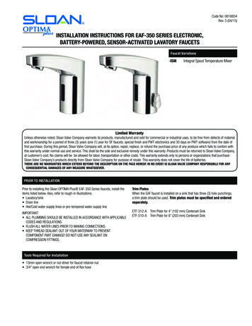
Code No. 0816308Rev. 2 (11/08)INSTALLATION INSTRUCTIONS FORSENSOR ACTIVATED HAND WASHING FAUCETSModel ETF-700-S-HModel ETF-500-S-H24 VAC, Sensor ActivatedHand Washing Faucet24 VAC, Sensor ActivatedHand Washing FaucetWith Surgical Bend Spout andShower Spray HeadWith Surgical Bend Spout andShower Spray HeadModel ETF-700Model ETF-50024 VAC, Sensor ActivatedHand Washing Faucet24 VAC, Sensor ActivatedHand Washing FaucetWith Standard Spout and LaminarFlow Spray HeadWith Standard Spout and LaminarFlow Spray HeadCompliant to: ASME A112.18.1and CSA B125.1LIMITED WARRANTYSloan Valve Company warrants its ETF-500 and ETF-700 Faucets to be made of first class materials, free from defects of material or workmanship under normal use and to perform theservice for which they are intended in a thoroughly reliable and efficient manner when properly installed and serviced, for a period of three years (1 year for special finishes) from date ofpurchase. During this period, Sloan Valve Company will, at its option, repair or replace any part or parts which prove to be thus defective if returned to Sloan Valve Company, at customer'scost, and this shall be the sole remedy available under this warranty. No claims will be allowed for labor, transportation or other incidental costs. This warranty extends only to persons ororganizations who purchase Sloan Valve Company's products directly from Sloan Valve Company for purpose of resale.THERE ARE NO WARRANTIES WHICH EXTEND BEYOND THE DESCRIPTION ON THE FACE HEREOF. IN NO EVENT IS SLOAN VALVE COMPANY RESPONSIBLE FOR ANY CONSEQUENTIAL DAMAGESOF ANY MEASURE WHATSOEVER.PRIOR TO INSTALLATIONPrior to installing the Sloan ETF-500 or ETF-700 Faucet, install the itemslisted below. Refer to Rough-in illustrations on Page 2. When Using Plug-In Transformer — Install electrical receptacle for plugin transformer (120 VAC, 2 amp service for each ETF-233(24 VAC, 35 VA) plug-in transformer used). When Using Box Mount Transformer — Install electrical wiring totransformer location (120 VAC, 2 amp service for each EL-248-40(24 VAC, 40 VA) transformer used). Scrub or wash-up sink Drain line Hot and cold water supply lines or tempered water supply lineMultiple FaucetsMultiple faucets can be powered by a single transformer, provided that thetransformer has been properly sized. Allow a minimum of 15 VA of currentrating for each solenoid valve used. Refer to “Step 4 — Install Transformer”for further information.Mixing ValveWhen installing the faucet with a Sloan mixing valve, these InstallationInstructions AND the Installation Instructions packaged with the mixing valveMUST be followed.Important: INSTALL ALL ELECTRICAL WIRING IN ACCORDANCE WITHNATIONAL/LOCAL CODES AND REGULATIONS. INSTALL ALL PLUMBING IN ACCORDANCE WITH APPLICABLE CODESAND REGULATIONS. A 24 VAC STEP-DOWN TRANSFORMER MUST BE USED. USE APPROPRIATE PRECAUTIONS WHILE CONNECTING TRANSFORMERTO 120 VAC POWER SOURCE. DO NOT PLUG TRANSFORMER INTO POWER SOURCE (RECEPTACLE)UNTIL ALL WIRING IS COMPLETED. ALLOWING 24 VAC TRANSFORMERWIRES TO TOUCH OR SHORT WHILE POWER IS BEING SUPPLIED WILLCAUSE PERMANENT DAMAGE TO THE TRANSFORMER AND CIRCUITCONTROL MODULE. KEEP THREAD SEALANT OUT OF YOUR WATERWAY TO PREVENTCOMPONENT PART DAMAGE! DO NOT USE ANY SEALANT ONCOMPRESSION FITTINGS. FOR THREADED PIPE FITTINGS, DO NOT APPLYSEALANT TO THE FIRST TWO “STARTER” THREADS. FLUSH ALL WATER LINES UNTIL WATER IS CLEAR BEFORE CONNECTINGSOLENOID TO SUPPLY STOPS.DO NOT INSTALL THE SPRAY HEAD UNTIL AFTER THE SUPPLYLINES HAVE BEEN FLUSHED.FLOW RATEThe ETF-500-H and ETF-700-H Faucets with a shower spray headincorporate a 2.2 gpm (8.3 Lpm) maximum flow control. If water flow is tooforceful, reduce flow to faucet by adjusting supply stops. If a pressurereducing valve has been installed, adjust valve until optimum spray isobtained. Best performance is obtained between 25 and 40 psi.BAK-CHEK TEE USAGEWhen connecting the Sloan ETF-500 or ETF-700 Faucet to both hot and coldwater supplies, a Bak-Chek Tee is provided and required as illustrated in theRough-in drawings on Page 2. Water temperature can be controlled byadjusting the supply stops.When connecting the faucet to a single line water supply or a pre-temperedwater supply, a Bak-Chek Tee is not required.A Bak-Chek Tee is not required or provided when a Temperature MixingValve is included with the faucet.TOOLS REQUIRED FOR INSTALLATION Open end wrenches for hex sizes:1/2”, 5/8”, 11/16”, 15/16”, 1-3/16” Slotted screwdriver (supplied) Pliers Pipe Wrench (ETF-500) Basin wrench Slotted screwdriver, 3/16” Phillips head screwdriver, #2 Wire stripper/crimping tool
FAUCET ROUGH-INETF-500 Faucet with Bak-Chek Teefor Hot and Cold Water SupplyETF-700 Faucet with Bak-Chek Teefor Hot and Cold Water SupplyETF-500-H with Standard Spoutand Shower Spray HeadETF-500 Faucet with BDM and BDTVariation Mixing Valves for Hot andCold Water SupplyETF-700 Faucet with ADM Variation MixingValve for Hot and Cold Water Supply(shown with 8” trim plate)ETF-700 Faucet with BDM and BDT VariationMixing Valves for Hot and Cold Water SupplyETF-700-H with Standard Spoutand Shower Spray HeadETF-500-S-H with Surgical BendSpout and Shower Spray Head2ETF-700-S-H with Surgical BendSpout and Shower Spray Head
1AInstall ETF-700 Faucet1BNote: When installing with a Sloan MIX-110-AA Mixing Valve,install Mixing Valve and Trim Plate before installing Faucet. Forcomplete installation guidelines, refer to the InstallationInstructions supplied with the Sloan mixing valve.AWhen optional Trim Plate is used, place Spacer between deck andTrim Plate making certain that Spacer is aligned with hole in TrimPlate and hole in deck.Insert Sensor Cable andSpout Shank throughRubber Washer and thenthrough center deck hole.TRIM PLATEW/SPACER(OPTIONAL)OPTIONAL ANTI-ROTATION FEATURENote: The anti-rotation feature uses a screw to anchor the faucet in thevertical position and is intended for use ONLY on stainless steel sinks.APlace the Base Gasket over the faucet mounting hole using it as atemplate.BMark the stainless steel mounting surface at the center of smallhole at the bottom of Base Gasket.FAUCET MOUNTING HOLE OFSTAINLESS STEEL SURFACESPOUTBInstall ETF-500 FaucetDRILL 7/64” (3 mm)HOLE AT MARKPLACED ON STAINLESSSTEEL MOUNTINGSURFACESTAINLESS ETSELF-TAPPINGSCREWFLAT WASHERLOCKWASHERCDrill a 7/64" (3 mm) diameter hole through the stainless steelmounting surface at the location just marked.DAfter Faucet body is mounted, insert the Self-Tapping Screwthrough the drilled hole and into the small hole in the back of theFaucet body. Tighten the Screw.NUTCSecure using Flat Washer, Lockwasher and Nut supplied.1BInstall ETF-500 Faucet (Continued)Note: When installing the faucet with a Sloan mixing valve, both these Installation Instructions AND those packaged with the mixing valve MUST be followed.TO MOUNT ON A SURFACE LESS THEN .41 INCH (10 mm) THICKARoute Sensor Cable through groove on side of Spout Shank.BInsert Sensor Cable and Spout Shank through Base Gasket andMounting Hole of sink.CSecure Faucet with the Flat Washer, Lockwasher and NutSupplied.NUT LOCKWASHERFLAT WASHERSENSOR CABLESPOUT SHANKTO MOUNT ON A SURFACE BETWEEN .41 INCH (10 mm) AND 1INCH (25 mm) THICKAScrew Mounting Stud into end of Spout Shank.BRoute Sensor Cable through groove on side of Spout Shank.CInsert Sensor Cable and Spout Shank through the Base Gasketand then through the mounting hole of scrub or wash-up sink.DFrom behind wall, install Mounting Spacer onto Faucet Shank asillustrated. The Mounting Stud should protrude through the smallerhole of the Mounting Spacer.ESecure using the Flat Washer, Lockwasher and Hex Jam Nutsupplied. Do NOT overtighten the Hex Jam Nut.FInstall Male Connector into Spout Shank.HEX JAM NUTDO TGASKETSHANKMOUNTINGSTUDFLAT WASHERHOLE OF SCRUB ORWASH-UP SINKBASE GASKETFAUCETMALE CONNECTORNote: Sloan Valve Company does NOT supply hardware necessary for mounting the faucet on surfaces thicker than 1” (25 mm) thick.3
2Install Solenoid ValveIMPORTANT: Keep thread sealant out of your waterway to preventcomponent part damage! DO NOT use any sealant on compressionfittings. For threaded pipe fittings, DO NOT apply sealant to the firsttwo "starter" threads.Note: Flow direction of Solenoid Valve is indicated by arrow onthe Valve Body.AAETF-500 Faucet Only — Thread Tube Compression Fitting intoinlet hole at bottom of Spout Shank; tighten securely to preventleaks.ETF-700 Faucet Only —Install the 3/8 inch Straight CompressionFitting onto the Spout’s copper Supply Tube.ETF-700ETF-500SPOUTSPOUTSPOUT SHANK1/8” (3 mm) NPTPIPE TO 3/8”(10 mm) TUBECOMPRESSIONFITTING1/8” (3 mm) NPTPIPE TO 3/8”(10 mm) /8” COPPERSUPPLY TUBE(NOT SUPPLIED)B33/8" COPPERSUPPLY TUBE(NOT SUPPLIED)3/8” (10 LENOIDVALVE3/8" COPPERSUPPLY TUBE(NOT SUPPLIED)3/8” (10 mm)BAK-CHEK COMPRESSIONTEE3/8" (10 mm)BAK-CHEK COMPRESSIONTEEAll Faucet Models — Connect 3/8 inch O.D. Supply Tube between Compression Connection on outlet side of Solenoid Valve and CompressionFitting on Spout.Connect Supply Line(s) fromSupply Stop to Solenoid Valve Inlet4Important: Keep thread sealant out of your waterway and preventcomponent part damage! Do not use sealant on compression fittings.When thread sealant is used, do not apply it to the first two “starter”threads.SOLENOIDMultiple faucets can be powered by a single transformer that has beenproperly sized. Allow a minimum of 15 VA of current rating for eachsolenoid valve used. Refer to the following example to determine therequired current rating for 3 OPTIMA faucets.For Dual Line Hot and Cold WaterSupply Applications3/8” (10 mm)SUPPLY TUBEInstall a 3/8 inch (10 mm) copper supplytube between Bak-Chek Compression Tee3/8” (10 mm)and hot and cold supply stops. (SupplyCOMPRESSIONstops and copper supply tube furnished byFITTINGinstaller.) Install a 3/8 inch (10 mm) coppersupply tube between Bak-Chek Compression Tee and inlet side ofSolenoid Valve. TightenCompression Fittings securely.3/8” (10 mm)Note: Failure to install the Bak-Chek TeeBAK-CHEK TEEUSED ON DUALcan result in a cross flow connectionSUPPLYWATER SUPPLYwhen the faucet is off and the supplySTOPAPPLICATIONSstops are open. If pressure of the hotONLYand cold water supply differ, hot watercan migrate into the cold water supply orSOLENOIDvice-versa. Most plumbing codes require thatVALVEthe Bak-Chek be used to prevent this.For Single Line Water Supply ApplicationsInstall a 3/8 inch (10 mm) copper supply tubebetween the supply stop and inlet side ofSolenoid Valve. (Supply stop and coppersupply tube furnished by installer.) TightenCompression Fittings securely.Example:Total number of OPTIMA faucets:Total number of solenoid valves:Multiply by current rating:3315 VA——Minimum current rating of required transformer: 45 VATransformers Available with the ETF-500 and ETF-700 FaucetsStandard Plug-In †Standard Box MountETF-233EL-248-40120 VAC120 VAC35 VA40 VA† In Canada, use ETF-416 (120 VAC, 35 VA).Optional Transformers Available from SloanBox MountFoot MountBox MountEL-154EL-208EL-342120 VAC120 VAC240 VAC50 VA100 VA50 VAAll Sloan transformers are 50/60 Hz.Other transformers (not supplied by Sloan) may be used, provided theymeet UL requirements for Class 2 transformers.3/8” (10 mm)SUPPLY TUBE3/8” (10 mm)COMPRESSIONFITTINGSUPPLYSTOPImportant: Flush dirt, debris, and sediment from the supply line(s).Install TransformerMultiple FaucetsVALVEABCOPPERSUPPLY TUBE3/8” COPPERSUPPLY TUBE(NOT SUPPLIED)SOLENOIDVALVE4
4Install Transformer (Continued)Plug-in TransformersCONTROLMODULEBASEImportant: DO NOT plug Transformer into receptacle until all wiring hasbeen completed.The Transformer is supplied with a 10 foot Cable; however, this Cablecan and should be shortened to meet installation requirements.AStrip ends of Transformer Power Cable approximately 3/16 to1/4 inch (5 to 6 mm).BInstall Strain Relief 3 inches (76 mm) from one end of PowerCable.CInsert Power Cable and Strain Relief into hole at back ofControl Module. Install right angle Strain Relief so that PowerCable enters the Control Module from the bottom.STRAIN RELIEFPLUG-INTRANSFORMER(ETF-233 SHOWN)PLUG-IN TRANSFORMERTRANSFORMERTERMINALSImportant: Twist stranded ends of Power Cable before inserting intoTerminal Block. Fraying of Stranded Power Cable Wire can cause ashort and damage the Control Module and Transformer when powered.DConnect Power Cable to Terminal Block on Connector Board.See Step 6.EInstall Crimp Connectors and connect Power Cable ends toTransformer Terminals.CRIMP CONNECTORSPOWER CABLEBox Mount Transformers5Important: DO NOT supply power to primary side of Transformer untilall wiring has been completed.Mount Transformer on a metal electrical junction box (supplied byothers). (“J” box should be mounted inside chase wall or aboveceiling.) Install Transformer within 50 feet (15.24 meters) of Faucet.18 gauge wire is recommended.ARun wires from secondary side of Transformer to 3/8 inch(10 mm) hole at back of Control Module Enclosure. Ifnecessary, wires can be run through wall and then insertedthrough hole in back of Control Module Enclosure.24 VACSECONDARYMount Control Module to WallAInstall the Control Module in an appropriate location as shown inRough-in. Control Module must be installed so that all cablesenter from the bottom of the unit. When installed, Cables from theSpout and Solenoid Valve to the Control Module should havesome slack.BMount Control Module to wall using Mounting Screws and PlasticAnchors.4” (102 mm)120 VACPRIMARYBOX MOUNTTRANSFORMER(EL-248-40 SHOWN)EXTENSION CABLESExtension Cables are available as an option from Sloan to allowfor installing the Control Module remote from the Faucet Spoutand Solenoid Valve. Refer to the Parts List for available lengths.5
6Control Module ConnectionARoute Cables from Solenoid Valve and Spout to the ControlModule.B7APlug In TransformerPlug Transformer into 120 VAC Receptacle.Insert Solenoid Valve Connector into the Modular Receptacle onConnector NAL BLOCK 1. REMOVETERMINAL BLOCK2. INSERT POWERCABLES3. SECURE WITHSCREWS4. REINSTALLTERMINAL BLOCKCONNECTORBOARDPOWERCABLESTRAIN RELIEF SLOTSTRANSFORMERFROM SOLENOIDVALVEFROM FAUCET SPOUTFROM TRANSFORMERCInsert Locking Connector from Faucet Spout into matingReceptacle on Connector Board. Allow 3 to 4 inches (76 to 102mm) of Cable to extend into the Control Module.DInsert each Conduit Cable into a strain relief slot in the ControlModule.8AStart-up9Range AdjustmentThe OPTIMA ETF-500 and ETF-700 Faucets are factory set to operatewhen hands are placed 4 to 5 inches (102 to 127 mm) from Sensor. Thisrange should be satisfactory for most installations.If range adjustment is required, refer to the following range adjustmentprocedures.Supply power to Transformer.Note: The Control Module is equipped with two LED lights. When poweris supplied by the Transformer, one LED will illuminate green. WhenSensor is activated, this LED will change to red. A second red LEDilluminates when Solenoid Valve is activated.TO MAKE A RANGE ADJUSTMENTThe Range Potentiometer and Dip Switches are located in Control Module.Important: Range Potentiometer adjustment screw rotates only 3/4 of aturn; DO NOT over-rotate.BMake certain that Dip Switch number 4 is in the UP position. Using thesmall screwdriver provided, adjust Range Potentiometer clockwise untilgreen (power ON) indicator LED turns red (Faucet is now picking up sink).Adjust Range Potentiometer back counterclockwise until red LED returnsto green. Range is now at maximum.Open Supply Stop(s). With Aerator removed, activate Faucet for30 seconds by placing hands in front of Sensor. The SolenoidValve should “click” and water should flow from the Spout. If thisdoes not occur, refer to the Troubleshooting section of thisinstruction instructions.Cycle Faucet several times to assure that range as adjusted will notinadvertently pick up IR reflection in lavatory. If IR reflection occurs (greenLED will flicker red), adjust Range Potentiometer counterclockwise veryslightly and again cycle Faucet.Repeat range adjustment counterclockwise until length of range is at bowlrim of lavatory (plus or minus 1” (25 mm)).CClose Supply Stop(s) and install Spray Head in Spout using theKey provided. Reopen Supply Stop(s), activate Faucet and checkfor leaks.6
9Range Adjustment (continued)Test Faucet OperationTime Out AdjustmentThe Faucet Time Out Setting determines the maximum time the Faucet willrun upon continuous activation. This timing can be changed to meetindividual application requirements.Refer to Table 1 or label on cover of Control Module along with thefollowing instructions to set the desired Time Out. The Dip Switches usedto set the Time Out are located in the Control Module.Set the Time Out by configuring the number 1, 2 and 3 Dip Switches asshown in Table 1.ETF-5001. A continuous invisible beam ofinfrared light is emitted from theOPTIMA sensor located at thebase of the lavatory faucet.Table 1 — Time Out SettingsTime Out2. As the user’s hands enter thebeam’s effective range (beneaththe spray head), the beam isreflected back into the sensorreceiver and activates thesolenoid valve. Tempered waterflows from the faucet into thesink until the hands are removedfrom the beam or until the faucetreaches an automatic time outlimit setting.Dip Switch SettingSwitch #1Switch #2Switch #33 SECONDSUPUPDOWNUP6 SECONDSDOWNDOWN12 SECONDSUPDOWNUP30 SECONDSUPDOWNDOWN45 SECONDSUPUPUP1 MINUTEDOWNUPUP3 MINUTESDOWNDOWNDOWN20 MINUTESDOWNUPDOWN3. When hands are moved awayfrom the sensor, the loss ofreflected light initiates anelectrical signal that deactivatesthe solenoid valve, shutting offthe water flow. The circuit thenautomatically resets and is readyfor the next user.Unless otherwise specified, all ETF-500/ETF-700 Faucets leave the factoryset with a 30 second Time Out.Note: The position of Dip Switch # 4 (range enhancer setting) does notaffect Faucet Time Outs.Push Cables into slots at the bottom of the Control Module.Install Control Module Cover using Screws provided. Refer to illustration inStep 7.CARE AND CLEANING OF CHROMEAND SPECIAL FINISHESDO NOT use abrasive or chemical cleaners (including chlorine bleach) toclean faucets that may dull the luster and attack the chrome or specialdecorative finishes. Use ONLY soap and water, then wipe dry with cleancloth or towel.When cleaning the bathroom tile, protect the faucet from any splattering ofcleaner. Acids and cleaning fluids will discolor or remove chrome plating.7ETF-700
TROUBLESHOOTING GUIDE2. PROBLEM: Sensing Range is too short.Note: Remove Cover from Control Module to check diagnostic lights.1. PROBLEM: No water is delivered when Faucet is activated.CAUSE: Extended Range Sensitivity is required.SOLUTION: Dip Switch number 4 should be in the “DOWN” (ExtendedRange Sensitivity) position. Increase range by adjusting RangePotentiometer clockwise (yellow phillips screw in blue base).ETF-500INDICATOR: If no LED lights illuminate:CAUSE: No electricity is being supplied toFaucet.SOLUTION: Ensure that the main power is turned“ON.” Check all Transformer,Sensor, Solenoid and CableConnections. Make sure thatTransformer is supplying 24 VACETF-700(Volts AC). If no voltage is detected,replace Transformer.CAUSE: There is an electrical systemmalfunction.SOLUTION: Reset electrical system. UnplugSensor Connection. Disconnectpower to circuit for ten (10)seconds. Reconnect.INDICATOR: If the GREEN LED does NOT illuminate when power isreconnected:CAUSE: There is an electrical system malfunction.SOLUTION: Reset electrical system. Unplug Sensor Connection.Disconnect power to circuit for ten (10) seconds. Reconnect.CAUSE: The Control Module circuit is “dead.”SOLUTION: Replace ETF-450-A Control Module.INDICATOR: If GREEN LED illuminates AND changes to RED whenhands are in the Sensor’s detection zone AND the RED SolenoidLED illuminates:CAUSE: Water supply stop(s) may be partially closed.SOLUTION: Open supply stop(s) completely.CAUSE: Debris is clogging Solenoid Filter.SOLUTION: Shut off water supply. Remove, clean and reinstall SolenoidFilter.INDICATOR: If GREEN LED illuminates AND changes to RED whenhands are placed in the Sensor’s detection zone AND the REDSolenoid LED flickers with a vibrating/clicking noise heard insidethe module:CAUSE: There is a direct short in the Solenoid or Solenoid Cable.SOLUTION: Replace with ETF-370-A Solenoid.INDICATOR: If GREEN/RED LED illuminates AND changes to REDwhen hands are NOT located in the Sensor’s detection zone BUTthe RED Solenoid LED (in upper left corner of circuit) does NOTilluminate:CAUSE: Sensor range is set too long and is detecting the sink.SOLUTION: Reduce Sensor detection range.CAUSE: Sensor is faulty.SOLUTION: Replace Sensor.INDICATOR: If GREEN LED illuminates BUT does NOT change toRED when hands are placed in the Sensor’s detection zone:CAUSE: Sensor range is set too short.SOLUTION: Increase Sensor detection range.CAUSE: Sensor is faulty.SOLUTION: Replace Sensor.3. PROBLEM: Faucet activates by itself (false triggers).CAUSE: Sensor range is set too long.SOLUTION: Decrease range by adjusting Range Potentiometercounterclockwise. If necessary, flip Dip Switch number 4 tothe “UP” (Reduced Range Sensitivity) position. Checksurroundings for factors that contribute to Sensor rangedetection problems (bright lights, highly reflective surfaces,sunlight, etc.).CAUSE: Faucet has Surgical Bend Gooseneck Spout.SOLUTION: For Long Range use (recommended for Surgical BendGooseneck Spout Faucet models), remove Range Jumper fromupper right hand corner of Circuit Board. Adjust RangePotentiometer.4. PROBLEM: Faucet delivers very low flow or just a dribble.CAUSE:SOLUTION:CAUSE:SOLUTION:Water supply stop(s) may be partially closed.Open supply stop(s) completely.Debris is clogging Solenoid Filter.Shut off water. Remove, clean, and reinstall Solenoid Filter orinstall Solenoid Valve repair kit ETF-1009-A.CAUSE: Solenoid is worn or faulty.SOLUTION: Rebuild with ETF-1009-A Solenoid Repair Kit or replace ETF370-A Solenoid.CAUSE: Debris is clogging Faucet Aerator or Spray Head.SOLUTION:Shut off water. Remove Aerator or Spray Head (use Key ifrequired). Clean and reinstall Aerator or Spray Head.5. PROBLEM: Faucet does not stop delivering water or continues todrip after user is no longer detected (even after power to theModule has been disconnected).CAUSE: Solenoid Valve is installed backward.SOLUTION: Disconnect Solenoid. Reconnect Solenoid with water flowtoward the Faucet (see arrow on Solenoid).CAUSE: Debris is clogging Solenoid.SOLUTION: Remove and clean Solenoid Operator. If necessary, rebuildwith ETF-1009-A Repair Kit.CAUSE: Seat in Solenoid Valve body is damaged or pitted.SOLUTION: Replace with ETF-370-A Solenoid.When assistance is required, please contact Sloan Valve CompanyInstallation Engineering Department at:1-888-SLOAN-14 (1-888-756-2614) OR 1-847-233-20168
PARTS LISTETF-500 MODELSETF-700 MODELS1A1D1C1B223B3B3A3A4B4B4A4A4AHARDWARE FOR USE WHEN MOUNTINGFAUCET TO A SURFACE BETWEEN 0.41”(10 mm) AND 1’ (25 mm) THICKOPTIONAL TRIM PLATESFOR ETF-700 MODELS58OPTIONAL MIXING VALVES1415A6121115B101315C79Item PartNo. No.DescriptionCOMPONENTS SUPPLIED WITH FAUCET1A—Faucet/Sensor Assembly, Standard Gooseneck Spout (ETF-500)1B—Faucet/Sensor Assembly, Surgical Bend Gooseneck Spout(ETF-500-S)1CETF-472-A Faucet/Sensor Assembly, Standard Gooseneck Spout (ETF-700)1DETF-473-A Faucet/Sensor Assembly, Surgical Bend Gooseneck Spout(ETF-700-S)2ETF-178Aerator Adapter (not required for Shower Spray Head)3AETF-8010.5 gpm (1.9 Lpm) Laminar Flow Spray HeadETF-6212.2 gpm (8.3 Lpm) Laminar Flow Spray Head3BAC-55-A2.2 gpm (8.3 Lpm) Shower Spray Head4AEBF-110-A Spout Mounting Kit, includes Base Gasket, Large Flat Washer,Large Lockwasher, Large Nut, Mounting Stud, Small Flat Washer,Small Lockwasher, Small Nut, Anti-rotation Screw, MountingSpacer, and ETF-591 Tube Compression Fitting ConnectorETF-5911/8” NPT Pipe to 3/8” Tube Compression Fitting Connector4BETF-503-A Spout Mounting Kit, includes Rubber Washer, Flat Washer,Lockwasher, Mounting Nut, and ETF-530 Union CompressionFitting5ETF-5303/8" x 3/8" Union Compression Fitting6ETF-370-A Solenoid Valve, 24 VAC, includes Wire Harness7ETF-617-A 3/8” Bak-Chek Tee Compression Fitting8ETF-450-A Control Module Assembly9ETF-233Plug-In Transformer10EL-248-40 Box Mount Transformer11ETF-458-A Power Cable with Strain Relief and Crimp Connectors (Transformerto Control Module)OPTIONAL MIXING VALVES121314MIX-60-A Below Deck Mechanical Water Mixing Valve (BDM Variation)MIX-135-A Below Deck Thermostatic Water Mixing Valve (BDT Variation)MIX-110-AA Optimix Deck Mounted Water Mixing Valve (ADM Variation)(only available for ETF-700 faucet)NOTICE: The information contained in this document is subject to change without noticeItemNo.PartNo.DescriptionOPTIONAL TRIM PLATES FOR ETF-700 MODELS15A15B15C—ETF-697-A4" (102 mm) Centerset Trim Plate Kit (Faucet Only); includesBack-up Spacer, Self-tapping Screw and CP Single Hole TrimPlate AssemblyETF-608-A 8" (203 mm) Centerset Trim Plate Kit (Faucet Only); includes two(2) Finger Nuts, two (2) Washer Gaskets, two (2) Fender Washers,Base Gasket, Back-up Spacer and CP Single Hole Trim PlateAssemblyETF-106-A 8" (203 mm) Centerset Trim Plate Kit for Faucet with OptionalMixing Valve, includes Back-up Spacer, Self-tapping Screw andCP Dual Hole Trim Plate AssemblyMIX-101-A 4" (102 mm) Centerset Trim Plate Kit for Faucet with OptionalMixing Valve, includes Back-up Spacer, Self-tapping Screw andCP Dual Hole Trim Plate Assembly (not shown)FAUCET CABLE EXTENSION CORDSFaucet to Control ModuleETF-1005-26 26” (0.7 meter) LengthETF-1005-36 36” (0.9 meter) LengthETF-1005-72 72” (1.8 meter) LengthETF-1005-108 108” (2.7 meter) LengthSolenoid to Control ModuleETF-1003-36 36” (0.9 meter) LengthETF-1003-48 48” (1.2 meter) LengthETF-1003-72 72” (1.8 meter) LengthETF-1003-108 108” (2.7 meter) LengthSOLENOID VALVE REPAIR KIT——ETF-1009-A Solenoid repair kitETF-437-A Solenoid compression fitting kitFor additional information about Sloan Mixing Valves or Trim Plates, consult ourInstallation Instructions and Maintenance Guides.If further assistance is required, please contact the Sloan Valve Company InstallationEngineering Department at:1-888-SLOAN-14 (1-888-756-2614)SLOAN VALVE COMPANY 10500 Seymour Avenue Franklin Park, IL 60131Phone: 1-800-982-5839 or 1-847-671-4300 Fax: 1-800-447-8329 or 1-847-671-4380www.sloanvalve.comCopyright 2008 SLOAN VALVE COMPANY11-08
3 1BInstall ETF-500 Faucet(Continued) Note: When installing the faucet with a Sloan mixing valve, both these Installation Instructions AND those packaged with the mixing v alve MUST be followed. A Route Sensor Cable through groove on side of Spout Shank. Insert Sensor Cable and Spout Shank through Base Gasket and Mounting Hole of sink. B Secure Faucet with the Flat Washer, Lockwasher and Nut
