Transcription
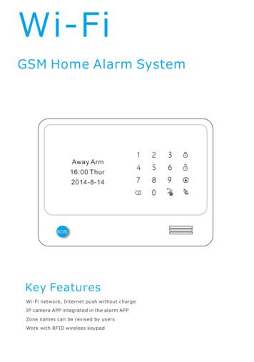
Wi-FiGSM Home Alarm SystemAway Arm16:00 Thur2014-8-14SOSKey FeaturesWi-Fi network, Internet push without chargeIP camera APP integrated in the alarm APPZone names can be revised by usersWork with RFID wireless keypad
Table of ContentsProduct IntroductionPreface1key features2Technical information/Front panel view3Back panel view4Main Function IntroductionAway arm4-5Home arm5-6Disarm6Voice message7Surveillance7Call up7Initialization8System setting8Detailed Functions SettingLearning Alarm SensorsRegister8-1111-12Defense Zone13Wireless Siren13Push/SMS AlertPhone NumberPasswordAlarm RecordingWi-Fi bonding1414-151515-1616
Time Set16-18Volume18-19Default setting19Machine Info19How to use Appvoice message functionIP camera function2020-22Home automation function22Call alarm host function23history checking function23alarm host setting function23-24Instruction for Wifi setting24-27Add equipment27Unbind equipment28Switch Equipment28Authorization29Logout29Wired zones sensor connectionWired beansWired PIR motion sensorwired door sensor3030-3131Wired and wireless relay outputsWired relay outputMaintenanceThe instruction for use wireless relay outputs3131-32MaintenanceSystem detection and Notice33
PrefaceThanks for choosing our GSM Wi-Fi home alarm system.GSM Wi-Fi home alarm system has implanted the most advanced andpopular Wi-Fi technology into traditional GSM alarm systemtechnology, with very simple wireless set up and easy-readwords OLED display.Itʼs very convenient for users to set up the alarm system viakeyboard or APP. Compared with traditional SMS APP, Wi-Fi APPis much more simple and quicker operation.Caution:To ensure that you can enjoy the impeccable warrantyservice, do not open the host-housing to repair and renovationby yourself or we will not provide free warranty service. All thelosses and the adverse consequences it makes will be assumedby users.1
Key features1.WIFI GSM word menu home alarm system.2.Android IOS APP application easily control, Easily Authorized.3.Notification push via Wifi, compare with traditional SMS, it'sfree.4.Work with IP camera, The IP camera APP intergrated in the hostAPP. you can view the IP camera by phone.5.Workable with RFID wireless keypad ,support doorbell function.6.Zone names can be revised by users.7.Relay usages name can be revised by users.8.Independent zones. Every zone can be set be independent zone,which can be only disarmed by APP and alarm host keypad.9.Leaving message remotely in APP. When leaving message in APP,such as: I will go home late,donʼt wait for me.Next the message isautomatically mapping to the host. Users will see LCD display note toremind.10. Information push promptly when AC power lost or recovered ordetectors in low voltage.11. Build-in wireless transmitter, can control 4 wireless relay outputsand wireless sound&strobe siren.12. 96 wireless zones 4 wired defense zones 4 wired relay, Canstore 6 alarm call phone No.13. Wireless encoding between host and detectors, innumerabledetectors for each wireless zone.14.Arm /alarm Delay for each defense zone. Timed arm /disarm function.15. 10-second voice message recording.16. Support Monitoring and two-way intercom function.17. The host can be used as a hand-free phone.2
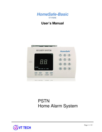
Technical informationPower supply: AC 100 230V 50Hz /60Hz Working voltage: DC12V 1A Static current: 35mA (when not in charging) Alarm current: 120mA Backup Battery: 3.7V 1750mA Standby time: Around 36 hours Charging time: 10 hours GSM frequency: 850/900/1800/1900MHz WiFi frequency:2.4G GSM Transmission power: 2W Receiving and emitting frequency: 433MHz (868MHzFront panel view:Away ArmOLED Display---------16:00 Thur2014-8-14-------SOSsos3------- Away Arm------- Disarm------- Home Arm- - -------- Dial /Confirm /Play-------- Return /Setting---------- Delete------ Siren
Back panel viewZ1Z2GND------------------------------- PowerJack------- ------- ----- Power Switch----------- Sim Card SlotZ3Z3GNDZ5Z6GND------------ Wired terminalZ7Z8GND 9VBZ- BZ Back panel viewZ1Z2GNDZ3Z3GNDZ5Z6GNDZ7Z8GND 9VBZ- BZ 9V Power supplyFour wired relay outputsFour wired zonesWired siren interfaceAway armIt means to guard all around your house while everyone is goingout;all the detectors of the host are always working; when thedetector is triggered by detecting source(anti-theft, fire prevention,gas leak, etc.),the alarm system will sound the alarm.4
SOSRemote Controller ArmApp ArmHost Panel ArmWireless Keypad ArmHome armIt means, for the safety, while somebody is at home, you need toenable the peripheral: door, window, balcony and boundary detectorsof the alarm system while prevent from triggering the indoor detectors,whichmay cause improper warning; then, you shall select Home Arm,let just part of the detectors work and disable the other parts.SOSRemote Controller Arm5Host Panel Arm
App ArmWireless Keypad ArmDisarmIt means to stop the alarm when the host sounds the alarm or makesthe alarm system in the state of non-warning. After disarming, evenif you trigger the detector, the host would not sound alarm (excluding24- hour defense areas).SOSRemote Controller DisarmApp Arm6Host Panel DisarmWireless Keypad Arm
Voice messageIt means recording voice message from APP to alarm host in orderto communicate between family members.Recording voice messagefrom APP to alarm host:Hold on touchbutton, start to record themessage,and no limitation for voice message length, the recordedvoice message will map to alarm host automatically.a new message2015-1-5SurveillanceIt means user can control IP camera directly from APP.(details takethe introduction of APP function for reference)Call upIt means alarm host can be used as a hand-free phone:(1)User can make dial directly from alarm host, touch phone number onnumeric keypad then touchtouchto make dial, after finish conversationagain to end the call.(2)User can make dial to alarm host, the person beside the alarm hostcan touchto answer the call. after finish conversation touchagain to end the call.7
InitializationFirst install sim card and connect the power supply in alarm host, thenswitch on the alarm host ,OLED display will appear “Wifi&GSM with ipcamera easy phone app 108sensors 101 devices more. Welcome!”,10seconds later, GSM signal icon and battery icon appear on OLED display,then initialization successes.Wifi&GSM withip camera easyphone app108 sensors101 devicesmore. Welcome!System settingTouchbutton, input 4 digital administration passwords, then canenter the setting menu for all the functions. If without furtheroperation for 35 seconds, alarm host will return to first page.Note: the factory default password is [0000]Detailed functions settingLearning alarm sensorsTouchbutton, input 4 digital administration passwords, Choose“learning sensor”menu, touchto get into sub-menu,display appear“is learning”,at the meantime trigger the alarm sensor, while it finishlearning,display will appear“success!”and the system will switch tozone type setting,user can choose alarm sensor type and defenseline in this sub-menu. Then touchto enter into “Zone Attribute”,user can choose function of delay alarm, join link, detect door, doorchime and independent in sub-menu.8
Main MenuStudy SensorLearning SensorRegisterDefense ZoneWireless SirenPush/SMS AlertAlarm Type24 Hours1st2ndZone TypeDoor SensorGlass DetectorGas DetectorSmoke DetectorSOS Detectoris learningZone AttributeDelay AlarmJoin LinkDetect DoorDoor ChimeIndependent[[[[[]]]]]How to learn RFID keypadTouchbutton, input 4 digital administration passwords, Choose“learning sensor”menu, touchto get into sub-menu,display appear“is learning”.Main MenuLearning SensorRegisterDefense ZoneWireless SirenPush/SMS AlertStudy Sensoris learningNow,user input user password or Administrator password on RFID keypadand then press any one button of away arm /disarm /home arm /doorbell .If the alarm panel make a sound like “beep”, then coding succeed. Users canchoose RFID keypad sensor type on panel. Then users can use RFID keypadcontrol alarm panel.Zone TypeWater DetectorPIR MotionBean DetectorRemoteRFID Detector9Zone TypeSuccess.
Zone typeUnder this menu, user can choose alarm sensor type, such as door/window sensor, gas detector, PIR motion sensor, fire detector, etc.Defense line124H defense line: it means 24 hours protection, the alarm sensorsin this line will trigger the alarm system whenever in arm status ordisarm status,usually panic button, smoke detector, gas leakagesensor, etc. should learn to 24H defense line.21st defense line: it means perimeter protection, the alarm sensorsin this line will work in both away arm and home arm modes.32nd defense line: it means interior protection, the alarm sensors inthis line will only work in away arm mode, but will be de-activated inhome /stay arm mode.Zone attribute1Alarm delay: Alarm delay setting is that the host will not alarm untildelayed time arrives.Touchto active and touchto de-active thisfunction.Note: for alarm delay time setting part, should refer to the menu“time set”,andchoose “alarm delay” sub-menu, enter time 00 to 99 sec for delayed time.Main MenuPhone NumberPasswordAlarm RecordingWifi BondingTime SetTime SetAlarm DelayArm DelayAlarm DelayAuto Arm/DisarmKeyLight TimeRing TimeAlarm DelayEnter Time00 Secupdate.2 Join link: If alarm sensor choose “join link” , then means this alarmsensor will active to work, if not chosen means will not work anytimein any status. Touch to activeand touch to de-active(factory default is active)Zone AttributeDelay AlarmJoin LinkDetect DoorDoor ChimeIndependent10[[[[[]]]]]this function.
3Door Chime:this function is suitable for main entrance gate installationto remind home owners that someone is coming in when the alarm systemin home arm or disarm status. Firstly, user need to program door sensorwhich want to set door chime function in 2rd defense line. secondly opendoor chime function under the “zone attribution” menu. After settingsucceed, if alarm system in disarm or home arm status, somebodyopen the main entrance gate, alarm host will make sound like“ding-dong”.Zone AttributeDelay AlarmJoin LinkDetect DoorDoor ChimeIndependent4[[[[[]]]]]Independent:Every zone can be set to be independent zone, whichcan only disarm by APP or alarm control panel, but can't disarm byremote controllers. The feature is suitable for important room orprivate room.Zone AttributeDelay AlarmJoin LinkDetect DoorDoor ChimeIndependent[[[[[]]]]]Register(wireless relay outputs /wireless siren)1 Wireless relay outputs: Touchbutton, input 4 digital administrationpasswords, choose “Register”menu, touchchoosing Device number touchto enter into sub-menuto learn ,OLED will display“register .”,at the meantime touch the learning button of relay output, after display“ success!”,then learning success.The device 4 to device 7 in alarm hostand APP are corresponding to wireless relay outputs control .11
Main MenuLearning SensorRegisterDefense ZoneWireless SirenPush/SMS AlertRegisterDEVICE-4DEVICE-5DEVICE-6DEVICE-7RF Socket2 RF Socket: TouchRF Device No.1Register.Successbutton, input 4 digital administration password,choose “Register”menu, touchSocket” touchRF Device No.1to enter into sub-menu choosing “RFto learn ,OLED will display “register .”,at the meantimepress the learning button of RF socket, after siren sound “beep-beep”andOLED display“ success!”,then learning success.RegisterRF SecketDEVICE-4DEVICE-5DEVICE-6DEVICE-7RF SocketRegister.3 RF indoor siren: TouchSuccessbutton, input 4 digital administration password,choose “Register”menu, touchsiren” touchRF Device No.1to enter into sub-menu choosing “ RF indoorto learn ,OLED will display “register .”,at the meantimepress the learning button of wireless siren, after siren sound“beep-beep”and OLED display“ success!”,then learning success.4 RF Outdoor siren: Touchbutton, input 4 digital administration password,choose “Register”menu, touchoutdoor siren” touchto enter into sub-menu choosing “RFto learn ,OLED will display “register .”,at themeantime press the learning button of wireless siren, after siren sound“beep-beep”and OLED display“ success!”,then learning success.12
Defense ZoneTouchbutton,input 4 digital administration passwords, choose “Defensezone”menu, Touchbutton to save operation. All the alarm sensors learnedinto alarm host would be automatically listed on screen. Users can chooseone sensor and touchbutton to review, edit and delete that sensor.ReviewIf the chosen alarm sensor has been already set zone type, defenseline,zone attribute, etc. then user can choose review to check theprevious setting history.Main MenuLearning SensorRegisterDefense ZoneWireless SirenPush/SMS 005ReviewReviewEditDeleteDefenseMain MenuZone Sensor Type Magnetometer Alarm Type 1stEditUnder the edit menu, user can set zone type of the chosen alarm sensor ,type defense line, zone attribute information or revise previous zone settinginformation.EditReviewEditDeleteZone TypeDoor SensorGlass DetectorGas DetectorSmoke DetectorSOS DetectorAlarm Type24 Hours1st2ndZone AttributeDelay AlarmJoin LinkDetect DoorDoor ChimeIndependent[[[[[]]]]]DeleteUser can delete the learned alarm sensors from this menu.DeleteReviewEditDeleteConfirmAre you sure?Revise zone name:user should refer to APP to revise zone name (take page 24 for reference)13
Wireless sirenTouchbutton, input 4 digital administration passwords, users canchoose “wireless siren” and then touchwireless siren. Touchsiren,and touchbutton to active or de-activeto active and touchto de-active wirelessbutton to save operation, then user can input thesiren ringing time (from 000 Sec to 999 Sec) in this sub-menu and pressbutton to save operation.Note: the factory default siren ring time is 300 Sec.Main MenuWireless SirenLearning SensorRegisterDefense ZoneWireless SirenPush/SMS AlertOutdoor On/Off [ ]Indoor On/Off [ ]Wireless SirenEnter Time300 SecPush /SMS AlertThis Function is for setting AC fail and recover alart, Arm /Disarmalert, alarm host battery low voltage alert, Sensor low battery alert,Wi-Fi ok or discon alert. Touchbutton, input 4 digital administrationpassword,user may choose “Push /SMS alert”.Enter the sub-menuTouchto active and touchto de-active the chosen function .Onceactive the listed event report, users can receive push /SMS alert whenevens happen.Main MenuLearningRegisterDefense ZoneWireless SirenPush/SMS AlertPush/SMS AlertAC FailAC okArm/DisarmBattery LowSensor Low[[[[[]]]]]Push/SMS AlertArm/DisarmBattery LowSensor LowWifi okWifi Discon[[[[[]]]]]Phone numberTouchbutton, input 4 digital administration passwords, user maychoose “phone number”, touch14button to enter alarm phone number
setting page. choose one group and touchnumber, touchbutton, then enter phonebutton to save operation. If user want revise the pre-setphone number, users may enter the chosen phone number page, andtouchtouchto delete the old phone number, and input new phone number,to save operation.Main MenuRegisterDefense ZoneWireless SirenPush/SMS AlertPhone NumberPhone NumberPhone NumberNo NumberNo NumberNo NumberNo NumberNo Number13555555555Phone Numberupdate.PasswordTouchbutton, input 4 digital administration passwords, user maychoose“Password”,Enter the sub-menu, user can revise “User Password”and “Admin Password”, choose one via touchto enter the next page,input new password and re-enter password to confirm, touchto savethe operation.Main MenuDefense ZoneWireless SirenPush/SMS AlertPhone :Modfy Pinupdate.Note:the factory default User password is 1111the factory default Admin password is 0000Alarm recording.Touchbutton, input 4 digital administration passwords, user maychoose “Alarm Recording” to start record voice message. this voicemessage will happen when user answering alarming call.15
Main MenuWireless SirenPush/SMS AlertPhone NumberPasswordAlarm RecordAlarm RecordingRecording.Wi-Fi bondingFor this part setting, user should refer to APP introduction to connectWi-Fi network (take page 24 for reference).Time SetThis Function is for setting time for set time zone, build-in Siren, Armdelay, Alarm delay, Auto Arm /Disarm etc.Main MenuPhone NumberPasswordAlarm RecordingWifi BondingTime Set1Time SetSet Time ZoneBuilt-in SirenArm DelayAlarm DelayAuto Arm/DisarmSet Time ZoneThis function is for auto timing via internet.Under this sub-menu,after user choose time zone,alarm host will auto timing.2Built-in SirenThis function is for setting the ringing time of build-in siren, user canchoose 000 Sec to 999 Sec. If choose 000 Sec, then means whenalarming, alarm host will keep mute.16Time SetBuilt-in SirenSet Time ZoneBuilt-in SirenArm DelayAlarm DelayAuto Arm/DisarmEnter Time300 SecBuilt-in Sirenupdate.
3Arm delayArm time delay setting is that the host will not be armed until delayedtime arrives. this function is mainly used for touch“arm”button in alarmhost to arm the system and leave time for user to deviate from house .Time SetSet Time ZoneBuilt-in SirenArm DelayAlarm DelayAuto Arm/Disarm4Arm DelayEnter Time00 SecArm Delayupdate.Alarm delayFirst user should active “alarm delay”function under the sub-menuof “zone attribute”which is mentioned in page 10. then setting timefor delayed alarm. this function is usually apply to leave time fordisarm via touching“disarm”button on alarm host panel.5Time SetAlarm DelaySet Time ZoneBuilt-in SirenArm DelayAlarm DelayAuto Arm/DisarmEnter Time00 SecAlarm Delayupdate.Auto Arm /DisarmIn total user can set three groups auto arm /disarm time .Under “TimeSet”, choose sub-menu “Auto arm /disarm”, choose “timer 1” as firstgroup, enter arm time and disarm time, and then press left /right buttonto choose day, pressTime SetClockBuilt-in SirenArm DelayAlarm DelayAuto Arm/Disarm17button to save.Auto Arm/DisarmArm/Disarm TimeTimer1Timer2Timer3Arm Time:10:00Disarm Time:12:00
Day uto Arm/Disarm]]]]]update.Key light timeUnder “Time Set”, choose sub-menu “Key light time”, and then entertime (00 99)(seconds).pressbutton to save.Note: if there is no further operation within key light time, then the panelwill exit setting status.Time SetBuilt-in SirenArm DelayAlarm DelayAuto Arm/DisarmKeylight Time7Keylight TimeEnter Time00 SecKeylight Timeupdate.Call in SettingUnder “Time Set”, choose sub-menu “Call in Setting”, and then enterringtime(00 99)(seconds).pressTime SetArm DelayAlarm DelayAuto Arm/DisarmKeylight TimeCall in Settingbutton to save.Call in SettingEnter Time00 SecCall in Settingupdate.VolumeTouchbutton, input 4 digital administration passwords,choose “volume”menu, touchbutton to enter system volume setting menu. In total usercan set key volume, voice volume alarm volume and ringer volume.18
Main MenuVolumePasswordAlarm RecordingWifi BondingTime SetVolumeVolumeKey VolumeVoice VolumeAlarm VolumeRinger VolumeDefault SettingAlarm RecordingWifi BondingTime SetVolumeDefault SettingVOL Machine InfoDefault SettingMain MenuVOL-Are you sure?Machine Info{Update Time}Jan 17 201520:22:44{Serial No}GAABDE51300014How to use AppAvailable on theApp StoreApple user search:"e wifi gsm alarm system"Google playAndroid user search:"WiFi GSM alarm system"User need input phone number,E-mail address, password in thisinterface.Firstly User need to register in APP. User need inputphone number, E-mail address, password in this interface.19
User need to Understand APP main interfaceAway Arm,Home arm /Stay arm,IP camera function.function,Disarm,voice message.Home automation function,history checking function,Call alarm hostsetting alarm host function.Introduction of voice message function as belowHold on pressing “message”button, record yourvoice message ,such as “donʼt wait for me fordinner ,I will go home late today”,this voicemessage will be automatically mapping to thehost. If user want to record a new voice message,just press “message”button again to start a newmemo, the new voice message will cover the oldvoice message automatically.Introduction of IP camera function as belowFirst:To better experience the convenience of this product, beforeusing this product, please download the Phone App.IOS users can go to the APP Store to search and download IP cameraApp:”2CU”Android users can visit the website (www.2cu.com) to download IPcamera App:”2CU”Second:Install IP camera APP in smart phone and register.Third:Enter alarm panel APP interface, pressmonitor buttonunder IP camera “Device List” interface, press button onthe top right corner to enter “Add device” interface.Add Device20Next
Fourth:Users can enter IP camera ID , pressNextbutton and then inputdevice name and input device password. PressSaveto finish adding.Note: IP camera ID is at the bottom sticker of IP camera. Users can definedevice name and default device password is 123.Fifth:Power on the IP camera and then connect IP camera with networkcable.Then the IP camera can connect with network. Refrash “Devicelist” , then users can see that IP camera would be “online”.Sixth:Connect IP camera with WiFi network.Click that IP camera device, appear “playback”, “setting” and “edit”buttons.Choose “Setting” to enter below interface.21
Seventh:Choose “Network Settings” to enter below interface.Eighth:Choose the accessable WiFi in the list, enter password, and pressOK button to finish setting.Finally:Then device can work with WiFi network and users can pull upthe network cable.Then press next step to finish installation.After installation, Once IPcamera is online(connect Power and Wi-Fi /wired internet), user cancheck what happening in his house any time and everywhere.Introduction of Home automation functionFor the method to connect wireless relay outputs , user can take page11, part 1 content for reference. Once connect wireless relay outputs(touch pad switch) successfully. User can control relays directly frombelow APP interface:Device 4 to Device 7 is for wireless relay outputs.Device 0 to Device 3 is for wired relay outputslocated in the behind of alarm control panel.22
Introduction of Call alarm host functionFirst Touchbutton, and find phone number setting in the first line,click it skip into next page like below picture. User need to input alarmhost SIM card No. in the last form.After store alarm host phone successfully, usercan touchbutton to call alarm host directlyfor listen-in what happen in house or intercomwith the person beside alarm host.Introduction of history checking functionThe history checking includes all pushes history and different typeof alarming history.Introduction alarm host setting functionIt includes host setting, zone attribution setting, and wireless sirensetting.Alarm host setting is for phone No. Setting,build-in siren ring time,arm delay,alarm delay,call in setting,auto arm&disarm,push /SMSalert,key press volume and keyboard lock setting.all the functionssetting listed in this page is same meaning as alarm host functionsetting.Zone attribution setting, all the learned alarm sensors will be listedin this page automatically.From zone-97 to zone-100 is for wired alarm sensor setting.From Zone-1 to Zone-96 is for wireless alarm sensors setting.23
Touch each zone number, the popping sub-page is for detailed functionsetting, including revising zone name(limitation for 16 letters),joinlinkage, door Chime and independent zone setting.Wireless Siren setting, user can revise siren name, join linkage ornot,set alarm time in this page.Instruction for Wifi setting.There are two way to connect Wifi Network.First, log in APP application, clickbuttonat top right corner in APP main interface.Second,click”wifi setup”of login interface.24
Android:Input userʼs house Wi-Fi name and password first, then wait for alarmpanel appear Now AP mode click"connect".Go to alarm control panel, log into main menu on setting. find Wi-FiBonding.Main MenuPush/SMS AlertPhone NumberPasswordAlarm RecordingWifi BondingWifi BondingNow AP mode click“Connect”Go to APP to click“connecting”When connect Wi-Fi success,APP will appear “smart configsucceed”When wifi iconappeared on first page, then means alarm hostconnect Wi-Fi network successfully.25
IOS:Firstly, enter APP WiFi setup interface.Secondly, click to enter panel “WiFi bonding”menu.Main MenuPush/SMS AlertPhone NumberPasswordAlarm RecordingWifi BondingWifi BondingNow AP mode click“Connect”Now, panel enter AP modeThirdly, users now press “home” button on iPhone to enter smartphone main interface, find the WiFi setting page.At this time userscan see the IWTAC hotspot which is also the hotspot of panel showedon iPhone. Users can connect iPhone with this hotspot, no need toenter password.Forthly, after successfully connect iPhone with IWTAC, users now canoperate APP, enter ssid and password of usersʼhome WiFi. Click“Connection”, then panel and APP enter bonding process.26
Wifi BondingSuccess!Fifthly, wait several seconds, then notification of operation succeedwill pop up both on panel and APP.Finally, after bonding success, APP will exit WiFi setup interface. Userscan connect iPhone with home WiFi hotspot. Then users can use APPcontrol panel.Note: if external power is cut off,alarm host use backup battery to work,then only GSM network works,but Wifi network will not work,asbackup battery is hard to support Wifi working for long time.Add equipmentFirst, log in APP application, clickbutton at top right corner in APPmain interface.Then Choose sub-menu “add equipment”,popping thebelow picture to scan the QR Code.27
Unbind equipmentFirst, log in APP application, clickbutton at top right corner in APPmain interface. Then Choose sub-menu “Unbind equipment”,poppingthe below picture ,user can touch “Unpin less” to unbind the presentequipment. Once unbinding success, popping tip “unpin less succeed”.Switch EquipmentFirst, log in APP application, clickbutton at top right corner in APPmain interface. User can touch “Switch Equipment”,popping the belowpicture ,and Short touch device name to switch the system.1.The iconturns green, means this device is online;if the iconturnsgray, means this device is off line.For example in picture 1 device nameGAA8DE4CW000030 is online and GAA8DE4CW000003 is off line.28
2. Hold on touch device name same as picture 2 to revise devicename. it will pop-up the dialog box as picture 3,input the new devicename in dialog box, touch ok button to confirm. After appear the tip“modify name success”,then modify device name is succeed.AuthorizationThe APP admin account can give authorization to two other mobilephone APP sub-account.First, log in APP application, clickbuttonat top right corner in APP main interface. Then Choose sub-menu“Authorization”.After choose the controlled device,user can touch dialog box themobile phone contact list will be pop-up.after choosing sub-accountmobile phone number from the contact list, the authorized phonenumber will be listed in picture 4.Note:authorize 2 phone No. at the most.After authorization is finished,user can revise the relation for eachnumber. click the member list,and input the name of relation into poppingdialog box,touch ok to confirm,then the relation name will be updated.LogoutUser can touch29button to return to login page.
Wired zones sensor connectionOnly mainstream wired sensors will be introduced here, such as wiredbeams, wired indoor PIR sensor and wired door sensor. These threekinds of wired sensors powered by panel, so users need to connectthem with panel power terminal.Wired Beamsusers need to connect bemas positive wire with 9V power terminalon panel and connect beams negative wire with GND terminal on pane.Wired beams signal output terminal should be connected with Z1/Z2/Z3/Z4 termina on panel, another output terminal should be connectedwith GND terminal on panel.Z1Z2GNDZ3Z4GNDZ5Z6GNDZ7Z8GND 9VBZ- BZ Note: For wired beams detector,its power consumption is a little large,so if install over than 2 pairs beams,need to use external power supply.Wired PIR motion sensorusers need to connect PIR positive wire with 9V power terminal onpanel and connect PIR negative wire with GND termina on panel. WiredPIR signal output terminal should be connected with Z1/Z2/Z3/Z4terminal on panel, another output terminal should be connected withGND terminal on panel.30
Z1Z2GNDZ3Z4GNDZ5Z6GNDZ7Z8GND 9VBZ- BZ Wired door sensorusers need to connect one output terminal with Z1/Z2/Z3/Z4 terminalon panel and connect another output terminal with GND terminal on panel.Z1Z2GNDZ3Z4GNDZ5Z6GNDZ7Z8GND 9VBZ- BZ Wired and wireless relay outputsWired relay outputThere are four wired relay output on panel, that is Z5,Z6,Z7 and Z8.Below is an illustration of lamp connection diagram.Z5AC adapter -31Z6GNDZ7Z8GND
The instruction for use wireless relay outputs----------------------------------- learning indicator light------------------------------------ programming button------------------------------------ jumper point̶ power supply------- appliances connection terminalsABCABCABCABCAC adapterAB CAttention:When you plug the Jumper between the 1, 2 pins, four bulbs willsimultaneously be opened and closed, or opened /closed several ofthem; when Jumper between the 2, 3 pins, you can only turn on onebulb once, for example, if you have already opened the '1' bulb,when open the “2” bulb,the'1' bulb will go off.123123There are four groups of "A/B/C" in a relay and one group will controlone set of circuit. As known to all that only a closed circuit formed theappliance works, that's to say the relay is a switch in this circuit.For example: If you would like the beside lamp controlled by the firstgroup, simply cut off the Fire Wire of bedside lamp circuit and reconnectthe two sides of A B. Of course, you can also be cut off the zero line toplug in A and B of the first group as well. Same goes for the second,third and fourth group.32
MaintenanceSystem detectionAlarm
Thanks for choosing our GSM Wi-Fi home alarm system.GSM Wi-Fi home alarm system has implanted the most advanced and popular Wi-Fi technology into traditional GSM alarm system technology, with very simple wireless set up and easy-read words OLED display. Itʼs very convenient for users to set up the alarm system via keyboard or APP.