Transcription
1STRUCTURAL INTEGRITY INVESTIGATIONSOnAdministration block located on Plot , Amuria District LocalGovernment HeadquatersProject No. 0071/AMRT/NOV-INT/2018REP. NO.: 0071/K’LA/NOV-INT/2018Prepared For:Project Contact: 256Prepared By:NOVEMBER, 2018Structural Integrity Assessment reportfor Administrative block on Plot ,Amuria district.
2TABLE OF CONTENTSECTIONPAGEEXECUTIVE SUMMARY . . 3INTRODUCTION . 4OBJECTIVE . 4SCOPE OF SERVICE . 7ACTIVITY DETAILS . 7STRUCTURAL DESCRIPTION . 8SITE AND SUBSURFACE CONDITIONS . 9REP. NO.: 0071/K’LA/NOV-INT/2018CLIMATIC DESCRIPTION .9REGIONAL GEOLOGY .11SESMOLOGICAL ASPECT .12METHODOLOGY .13STRUCTURAL INSPECTION AND ASSESSMENT .13SUBSOIL/ GEOTECHNICAL INVESTIGATION .14LABORATORY SOIL TESTING . 16PICTORIAL REPRESENTATION .22FINDINGS .28CONCLUSIONS AND RECCOMMENDATIONS .34APPENDIX .37REFERENCE AND BIBLIOGRAPHY .52Structural Integrity Assessment reportfor Administrative block on Plot ,Amuria district.
31.0.EXECUTIVE SUMMARYThis Executive Summary is provided as a brief overview of our laboratory based structuralintegrity assessment for the project and is not intended to replace more detailedinformation contained elsewhere in this report.For the design and analysis of the structural system of the as built structure, sub-soil andmaterials investigation had to be carried out to provide the design team with the requiredreliable information. As an overview, this summary inherently omits details that could bevery important to the proper application of the provided structural integrityrecommendations. Therefore, it should be read and used to its entirety with periodicREP. NO.: 0071/K’LA/NOV-INT/2018consultation with the investigating team. Below is a summary of key considerations;Material assessment of the existing structures was carried out by determining the as builtcompressive strength of selected structural members using a Schmidt rebound hammer forcompressive strength, rebar assessment, visual inspection for defects, structural memberdimension assessment, and sub soil investigation to ascertain foundation properties andsuitability.The subsurface exploration program consisted of two test pits (designated as TP 01through TP 02). Site subsurface conditions generally consisted of blackish clayey finegravel soils in the surficial layers, underlain by reddish brown clayey gravels. The as builtstructure was found to be supported on pad and strip foundation systems bearing on soilsof maximum allowable bearing pressure of 180Kpa at an average depth of 1.40 - 1.50mbelow ground level.Visual inspection was also done to check for any concrete surface defects. Some honeycombed surfaces were observed and sufficient concrete cover was observed to be providedto the reinforcement. Please note that all main bars in the as-built structure were of Ribbedtype (approx. 500 MPa tensile strength)Structural Integrity Assessment reportfor Administrative block on Plot ,Amuria district.
4With reference to the seismic hazard map of Uganda, the mean peak ground acceleration(PGA), which is exceeded on average once every 50 years, was calculated. It should benoted that the area in which the structure is located is in zone 3 of the seismic zoning ofUganda and far away from the rift valley regions, it is therefore unlikely for earthquakes tooccur with high frequency and magnitude.The rebound hammer test revealed that the both the assessed buildings had a compressivestrength that varies from 26 – 29Mpa. It is therefore recommended that a maximumcompressive strength of 26MPa be used to assess the existing building for structuralstability.REP. NO.: 0071/K’LA/NOV-INT/2018Some slab soffit areas were observed to have some staining, efflorescence, and blistering in,an indication of water penetration and saline conditions. This can easily lead to barcorrosion, later undermining reinforcement strength. We therefore call for immediateapplication of finishes to the slabs.There were a few exposed reinforcement bars as a result of insufficient concrete cover,though all the bars were observed to have undergone less corrosion.Compiled byEndorsed byP. OchiengLab EngineerDr. J. NyendeHEAD OF DEPARTMENTStructural Integrity Assessment reportfor Administrative block on Plot ,Amuria district.
52.0INTRODUCTION2.0.1 BACKGROUNDStructural integrity investigation is an assessment carried on an existing building to checkon limit state requirements as an assessment for suitability of its intended purpose. Thedesign of a structure is always based on the criterion of Safety -strength, stability androbustness, economy and appearance; however, in this case the structure underinvestigation was partially checked and assessed for the safety criteria.Amuria District is one of the Local Governments under the Uganda Governmentdecentralization policy, it is approximately 37 kilometers by road North of Soroti Districtand it is one of the largest towns in the Sub region. It is bordered by Otuke District to theREP. NO.: 0071/K’LA/NOV-INT/2018North, Napak and Kapelebyong District to the Northeast, Katakwi District to the East, SorotiDistrict to the South, Kaberemaido District to the Southwest, and Alebtong District to theWest. Amuria district made procurement procedure to construct its district localgovernment offices and it commenced with putting up the ground floor under the Worksand Technical Services Department. A proposal has been made to add more floor levels tothe building and this required to first ascertain the current structural stability conditions ofthe existing ground floor.As requested by the district Engineer, a team from the soil and concrete Laboratory of KyambogoUniversity set out to conduct a Laboratory based Structural Integrity assessment on the existingadministrative block, on plot No. , Amuria district local government. The structure is currentlyunder management of the district local government. The investigation was commenced on 04thNovember, 2018.This report details the engineering characteristics as discovered from the investigation thatinclude hardened concrete strength, rebar assessment details, sub soil investigation details,terrain and some building defects. It describes the general methodology that was used toconduct the investigations, and studies undertaken to assess structural stability and subsoil suitability.Structural Integrity Assessment reportfor Administrative block on Plot ,Amuria district.
6Information obtained from geological maps and available reports was used to set up thegeological outline of the project area and determine the foundation suitability for theexisting building.2.1OBJECTIVESThe main objective of this investigation was as to assess the stability and serviceability ofthe as-built structure with respect to the design and required standards as specified by thedesigner and city authority. It should be noted that structural drawings were not availed atthe time of the investigation.2.2SPECIFIC OBJECTIVESREP. NO.: 0071/K’LA/NOV-INT/2018The investigation comprised of:I.II.Carrying out Insitu Non-destructive concrete tests on selected structural members.Visual inspection on the structural masonry and concrete to establish signs of andfailure, and fatigue.III.Carrying out dimension inspections of the different structural members used inconstruction.IV.V.Carrying out a geotechnical/subsoil investigation on the siteAssessing the findings in comparison to the availed drawings and attachedgeotechnical investigation findings.VI.Compiling and submitting of a technical report.The positions of members to be tested were predetermined and marked out on thestructure for ease of identification during a field reconnaissance with the aid of the availedstructural Drawings. The key out puts of the both the laboratory and field activities areclearly stipulated in the following chapters.Structural Integrity Assessment reportfor Administrative block on Plot ,Amuria district.
72.3 ACTIVITY DETAILSThe table below indicates the planned activities and schedule of works as executed by theinvestigating team.S/N1234567REP. NO.: 0071/K’LA/NOV-INT/20182.4Works/activitySite visit and reviewField work (sampling)Insitu testLaboratory testsAnalysis and compilingreviewSubmission of reportInvolved teampersonnelTime (days)1 2 3 4 5 6 7 8 9 10Lab client consultantLab consultantLabLabLab consultantLab consultantLab client consultantSCOPE OF SERVICESThe purposes of our involvement on this project were to 1) provide general descriptions ofthe subsurface soil conditions encountered at the locations explored, 2) provide foundationdesign recommendations, and 3) comment on other geotechnical aspects of the proposeddevelopment. In order to accomplish the above objectives, we undertook the followingscope of services:I. Visited the site to prepare and mark points to be tested, on all selected concretestructural members.II. Reviewed and summarized readily available information regarding the proposedproject and the area.III. Conduct non - destructive concrete strength test on selected concrete members.IV. Executed a subsurface exploration consisting of two test pits excavations up tomaximum depth of about 2.5 - 3.00m in predetermined positions as required by thedesign team.V. Rebar assessment, building defects analysis and dimension checks on the differentstructural members.VI. Evaluation and analysis of the findings and prepare a technical reportStructural Integrity Assessment reportfor Administrative block on Plot ,Amuria district.
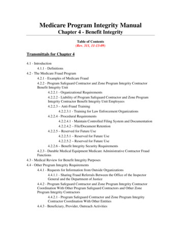
83.0STRUCTURAL DESCRIPTIONThe building under investigation is an incomplete single storied administrative building atthe time of investigation. The structure is a framed reinforced concrete structure havingreinforced concrete beams, columns, stair cases, footings and max span suspended slab.The walling infill material was found to be of common burnt clay bricks bonded in cementsand mortar of unknown ration/mix. The existing structure was as seen in the photo plateREP. NO.: 0071/K’LA/NOV-INT/2018below.Photo plate 01: the as built structure under investigation.Structural Integrity Assessment reportfor Administrative block on Plot ,Amuria district.
94.0SITE AND SUB SURFACE DESCRIPTION4.1SITE DESCRIPTION AND TOPOGRAPHYThe structure under investigation is located in within the district local governmentpremises of Amuria, on plot No. , Amuria District as previously stated. The site istopographically located along a gently sloping terrain. The areas in which the site is locatedis a renown Administrative area with other administrative department building within thevicinity. The site vegetation cover was found to be comprising of short grass cover withmature tropical trees with an on-road orientation.4.2PROJECT INFORMATIONREP. NO.: 0071/K’LA/NOV-INT/2018Our understanding of the project is based on information provided by mainly the districtEngineer, previous design documents and our experiences with similar projects. Thisreport is therefore purposed to aid in the structural - stability analysis of the existingunfinished administrative building under investigation and preparation of safe structuraldesigns and drawings for submission so as addition construction can safely be commenced.4.3PREVIOUS REPORTS AND INFORMATIONThere was no integrity or subsurface exploration information availed and therefore it wasassumed that this report entails the first ever investigation executed on the proposedstructure and site.Structural Integrity Assessment reportfor Administrative block on Plot ,Amuria district.
104.4CLIMATIC DESCRIPTIONThe rainfall pattern is greatly influenced by the existing relief and the presence of waterbodies, vast swamps and the area topography, which generally encourage evaporation anduplifts of winds causing precipitation during most parts of the year without any specifieddry and wet seasons. The average annual rainfall is estimated to exceed 1285mm perREP. NO.: 0071/K’LA/NOV-INT/2018annum. The temperature here averages 23.6 C. The average annual rainfall is 1285 mm.Structural Integrity Assessment reportfor Administrative block on Plot ,Amuria district.
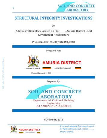
114.5 REGIONAL GEOLOGYThe site is located in an area underlain by partly Proterozoic rocks and Archean plutonicrocks partly reworked during later orogenic events. The soils were largely consisting oflaterite gravel material. The soils resulting from in-situ weathering of the rocks, withoutsignificant transportation, are called residual soils and these were observed through outthe site. The residual soil profile generally grades downward gradually from thin finegrained strata to coarse grained plastic strata up to explored depth as presented in the testpit logs. Some rock out crops were observed within the site and in the neighborhood.Further details about the site geology and geotechnical properties are represented in theREP. NO.: 0071/K’LA/NOV-INT/2018attached geotechnical report section.FIGURE 02: GEOLOGICAL MAP OF UGANDAStructural Integrity Assessment reportfor Administrative block on Plot ,Amuria district.
124.6SEISMOLOGICAL ASPECTSThe site is located in zone 3 of the seismic zoning of Uganda, implying that there is aslightly low frequency (and magnitude) of earthquake occurrence in the area. ( SeismicCode of practice for Structural Designs; Uganda National Bureau of Standards, FirstREP. NO.: 0071/K’LA/NOV-INT/2018Editions: June 2003) below is a seismological map of Uganda to justify this information4.7GROUND WATER TABLE (G.W.T)The standard method of determining GWT was adopted, in which whenever ground wateris encountered during excavation or drilling, the pits were covered to allow the water levelto stabilize for about 24 hours. The actual level of the static water table is there aftermeasured using a tape measure. In this case, the ground water was not encountered in anyof the excavated pits as presented in the test pit loggings.Structural Integrity Assessment reportfor Administrative block on Plot ,Amuria district.
135.0 METHODOLOGY5.1 STRUCTURAL INSPECTION AND ASSESSMENT METHODSBuilding inspection is a general surface examination of those parts of a property which areaccessible. In order to carry out the inspection, the engineer required some basicequipment to be used during the survey. In general four types of inspection weredistinguishable: these include visual inspection, concealed object inspection, Dampnessinspection, stress survey.5.1.1 Non-Destructive Rebound Hammer Test.This test was carried out with an N-type Schmidt mechanical rebound hammer. Theconcrete surface to be tested was first prepared by smoothening with a carborundumREP. NO.: 0071/K’LA/NOV-INT/2018stone. Care was taken to avoid honeycombed regions and wet surfaced concrete. At leastten shots of the hammer were taken on each chosen member, and the mean reboundreading of each member was recorded, corrected and used to obtain the averagecompressive strength. In the case of this building, no chiseling or hacking was required toremove plaster, since most of the members were exposed.5.1.2. Structural Member Dimensions AssessmentThis activity involved ascertaining the dimensions of the different structural members i.e.;the beams, slabs, and foundation footings. A calibrated tape measure was used, and werepossible, a Vernier caliper came into play.5.1.3. Reinforcement detail assessmentThis was carried out with the help of hand tools and equipment e.g. chisels mallets,micrometer screw gauge, and a Vernier caliper. Since the buildings under investigationwere found complete, a few members were chosen from each of the buildings, such thatthey can be chiseled to expose the reinforcement for analysis and assessment. Afterexposure, some of the exposed reinforcements were assessed to check for defects andmeasured to obtain their individual sizes. The chiseled points were later filled and finishedback to original surface finish.Structural Integrity Assessment reportfor Administrative block on Plot ,Amuria district.
145.2SUB-SOIL /GEOTECHNICAL INVESTIGATIONThe output of the sub-soil investigation is detailed in the geotechnical investigationfindings including all activities undertaken by the laboratory to ascertain the geotechnicalconditions. All structural foundation stability should be assessed with reference to thissection of the report.5.2.1 SUBSURFACE EXPLORATION PROCEDURES AND METHODSFollowing a review and evaluation of existing information regarding soil conditions, surveyreports and architectural details for the project, an investigation and testing program hasbeen developed and implemented. Field testing, sampling and laboratory testing has beenREP. NO.: 0071/K’LA/NOV-INT/2018designed to provide information as follows:5.2.2 Trial PitsTwo trial pits were sunk at approximate nominal distribution as presented on the sitelayout plan, each pit attaining a target depth of about 2.5 - 3.0m. Two of the test pits werelocated at foundation points. The test pitting operations were carried out manually with aidof hand tools such as hoes, spades and pick axes.The test pits were located in alternate positions of the site as requested by the design team.The aim of the excavation of trial pits was to determine the structure of existing sub soils,the type of underlying soils, including extraction of both disturbed and undisturbedsamples. In-situ density tests to determine the actual density of the underlying stratawhere carried out with aid of the core cutter method.5.2.4 Sampling:Bulk samples were taken from each of the test pits at 1.0 – 1.5m depth intervals forlaboratory testing. Representative soil samples obtained throughout the explorationprogram were placed in air tight containers and transported to the laboratory. In thelaboratory, the soil samples were classified in general accordance with techniques outlinedin the visual-manual identification procedure (ASTM D 2488) and the Unified SoilClassification System.Structural Integrity Assessment reportfor Administrative block on Plot ,Amuria district.
155.2.3 Dynamic Cone Penetration Test (DCP)Dynamic Cone Penetrometer (DCP) tests were conducted through the ground belowsurfacing to provide an estimate of the in-situ bearing capacities of the layers underneath.DCP tests at this stage were performed in the test pits at depth intervals of 1.50m,commencing from ground level as presented in the appendix on the site layout. Theprogram of dynamic cone penetrometer testing was carried out, using the TRL model conepenetrometer with 8kg hammer falling through a shaft of drop height 575mm, which internforces a 20mm diameter/60 degree cone into the encountered strata.The TRL DCP is an instrument designed for the rapid in-situ measurement of the structuralproperties of existing sub soil structure. Correlations have been established betweenREP. NO.: 0071/K’LA/NOV-INT/2018measurements with the DCP, CBR (California Bearing Ratio) and allowable bearingcapacity, so that results can be interpreted and presented appropriately for foundationdesign.5.2.5 Test pit loggingTest pit layer details were also examined recorded as profiles and are shown in detail in theappendix. The stratigraphy revealed by each pit was carefully logged with special notetaken to the thicknesses and conditions of the various layers. The soil descriptions andclassifications discussed in this report and shown on the attached test pit logs are generallybased on visual observation and should be considered approximate. Copies of the test pitlogs are provided and classification procedures are further explained in the Appendixattachments.Structural Integrity Assessment reportfor Administrative block on Plot ,Amuria district.
165.2.6 LABORATORY SOIL TESTINGLaboratory testing was carried out on samples obtained from the excavated test pits toidentify the physical properties of the soils, and obtain parameters for determining theirstrength and compressibility characteristics. The tests were conducted according to thefollowing standard methods given in table 03:Table 03; Laboratory tests carried out on samplesREP. NO.: 0071/K’LA/NOV-INT/2018Classification TestsStandard Test MethodSample statusMoisture contentBS 1377: Part 2: 1990DisturbedParticle size distributionBS 1377: Part 2: 1990“Liquid LimitBS 1377: Part 2: 1990“Plastic LimitBS 1377: Part 2: 1990“Plasticity IndexBS 1377: Part 2: 1990“Specific gravityBS 1377: Part 2: 1990“Chemical testsSulphate testsBS 1377: Part 3: 1990DisturbedChloride testsBS 1377: Part 3: 1990DisturbedpH testsBS 1377: Part 3: 1990DisturbedBS 1377: Part 4: 1990UndisturbedCompaction testsIn situ DensityLab Density determination BS 1377: Part 4: 1990DisturbedStrength testsShear strength testBS 1377: Part 7: 1990UndisturbedStructural Integrity Assessment reportfor Administrative block on Plot ,Amuria district.
175.2.6.1 CLASSIFICATION TESTSNatural Moisture ContentThis was carried out in accordance with BS 1377: Part 2: 1990. A specimen was obtainedfrom each of the samples delivered to the laboratory, and its weight taken. The specimenwas oven dried at temperatures between 1050C and 1100C for 24 hours and the dry weightwas also taken. The ratio of moisture loss (wet mass – dry mass) to the mass of the driedsoil expressed as a percentage is the moisture content of the specimen.Particle size distribution determination (sieve analysis)The standard method of wet sieving which conforms to BS 1377: Part 2: 1990 was adopted.A representative sample was taken from the main sample and oven dried at temperaturesREP. NO.: 0071/K’LA/NOV-INT/2018between 1050C and 1100C for 24 hours. The dried soil was weighed to obtain its dry mass,and after it was washed through a 0.063mm BS test sieve in accordance with the testmethod.The retained fraction was again oven dried for 24 hours at temperatures between 1050Cand 1100C, after which it was sieved through a series of BS test sieves arranges indescending order of aperture sizes to form a nest. Sieving was done. The fraction retainedon each sieve was weighed and the percentage passing each sieve was determined.Plastic Limit (PL)Plastic limit is the moisture content below which soil is not plastic (non-plastic). This testwas also carried out in accordance with BS 1377: Part 2: 1990. The samples used in thistest were prepared in the same manner as those for the liquid limit tests. The test consistedof rolling balls of soil pastes between the hands and then into threads between the palmand a glass plate. The plastic limit was the moisture content at which the threads developtransverse cracks when they were about 3mm diameter.Structural Integrity Assessment reportfor Administrative block on Plot ,Amuria district.
18Liquid Limit (LL)Liquid limit is the moisture content beyond which soil behaves like a viscous fluid.Therefore Liquid limit is a consistency limit of soil. The Liquid limit test was carried outusing the BS Cone Penetrometer in accordance with BS 1377: Part 2: 1990. A BS conePenetrometer fitted with an automatic timing device that ensures 5 second penetrationunder an 80gm load was used. Air dried representative samples were ground in a mortarand sieved through a 0.425mm BS test sieve. 200g of each of the sieved samples weremixed thoroughly with distilled water and there after the water was allowed to permeatethe samples overnight in an air tight container. The soils specimens were then remixed thefollowing day with sufficient water to achieve two penetrations in the range betweenREP. NO.: 0071/K’LA/NOV-INT/201815mm and 25mm. After each penetration, the respective moisture contents of thespecimens were determined. Moisture content, Penetration curve was plotted for each ofthe specimens from which the moisture content at 20mm penetration was taken to be theliquid limit.Plasticity Index (PI)The Plasticity index was determined in conformity with BS 1377: Part 2: 1990. ThePlasticity index is the numerical difference between the LL and PL. (PI LL – PL)Specific Gravity of soils (Gs)Specific gravity is in simple terms the relative density of soil, hence the ration of mass of agiven soil sample to the mass of an equal volume of water. This test was carried out withaccordance to BS 1377: Part 2: 1990. The density bottle method was used in this test wereeach of the air dried sample were ground with a mortar and pestle, and after sievedthrough a 2mm BS test sieve. About 50g of each of the sieved samples were placed inrespective bottles and there masses taken.These were treated to procedure complying with BS 1377: Part 2: 1990 to obtain theSpecific gravities for each of the samplesStructural Integrity Assessment reportfor Administrative block on Plot ,Amuria district.
195.2.6.2 CHEMICAL TESTSChemical tests were also conducted on the extracted soil samples, the sand material foundon site and also ground concrete samples from hardened concrete specimensSulphate testsIn this test, the gravimetric method was used, in accordance with BS: 1377: Part 3: 1990. Itinvolved obtaining 50gms of air dried samples were placed in extraction bottles and 100mlof distilled water added to each before covering tightly. These were then mounted ontoshakers and agitated for 16 hours. The soil suspensions were then filtered into clean anddry flasks. 50ml of the soil suspensions were dissolved in distilled water, after whichBarium chloride solution was added to each, to form a precipitate of Barium sulphate,REP. NO.: 0071/K’LA/NOV-INT/2018which was collected, dried and weighed. The Sulphate content was then calculated from themass of water used in the analysis and the mass of Barium sulphate precipitated.Chloride testsThis was done in accordance with BS: 1377: Part 3: 1990. 5gms of material passing the0.150mm BS test sieve was put in a beaker of 500ml volume. 50ml of distilled water wasadded followed by 15mlof concentrated nitric acid. The mixture was then heated to nearboiling point, cooled and filtered through coarse graded filter paper.The residue was washed with distilled water and all the filtrate collected. Silver nitrate wasthen added to the filtrate from burette until all the chlorides were precipitated.Titration was done with standard Potassium thio-cynate using ferric alum as an indicator.3, 5-5 trimethylhexan-1-ol was used to coagulate the precipitate.pH testThis test was performed in accordance with BS: 1377: Part 3: 1990, in which theElectrometric method was used to determine the pH of the soils. 10gms of an air driedsoil/sand/pulverized concrete sample was dissolved in distilled water and introduced intoa 100ml beaker and stirred for a few minutes then covered and allowed to stand for 8hrs.Calibration of the Ph meter was done initially using a standard buffer solution. Theelectrode was then washed with distilled water and immersed in the dissolved sample. Thecorresponding reading was taken with brief stirring between each reading.Structural Integrity Assessment reportfor Administrative block on Plot ,Amuria district.
205.2.6.3 SOIL COMPACTION TESTSIn situ Density DeterminationThis test was carried out in accordance with BS 1377: Part 4: 1990. The Core cutter methodwas used. This was done to determine the dry density (mass of dry soil per cubic meter) ofnatural or compacted soil in situ, since density is also an important parameter of strengthand a measure of the Degree of Compaction. The core cutter is a cylindrical metal of knowndimension (volume) and weight, and has a cutting sharp edge. The core cutter was driveninto the floor of the excavated pit at a suitable depth using a steel dolly. The core cutter wasthen later carefully extracted out of the pit, and it contained a core of soil. A small portion ofsoil was also taken and placed in an air tight container for relative moisture contentREP. NO.: 00
It should be noted that structural drawings were not availed at the time of the investigation. 2.2 SPECIFIC OBJECTIVES The investigation comprised of: I. Carrying out Insitu Non-destructive concrete tests on selected structural members. II. Visual inspection on the structural masonry and concrete to establish signs of and failure, and fatigue.