Transcription
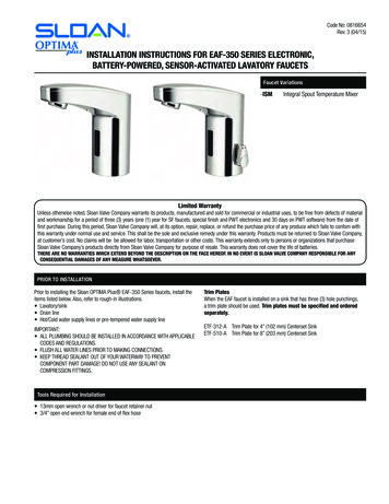
Code No: 0816654Rev. 3 (04/15)INSTALLATION INSTRUCTIONS FOR EAF-350 SERIES ELECTRONIC,BATTERY-POWERED, SENSOR-ACTIVATED LAVATORY FAUCETSFaucet Variations-ISMIntegral Spout Temperature MixerLimited WarrantyUnless otherwise noted, Sloan Valve Company warrants its products, manufactured and sold for commercial or industrial uses, to be free from defects of materialand workmanship for a period of three (3) years (one (1) year for SF faucets, special finish and PWT electronics and 30 days on PWT software) from the date offirst purchase. During this period, Sloan Valve Company will, at its option, repair, replace, or refund the purchase price of any produce which fails to confom withthis warranty under normal use and service. This shall be the sole and exclusive remedy under this warranty. Products must be returned to Sloan Valve Company,at customer’s cost. No claims will be be allowed for labor, transportation or other costs. This warranty extends only to persons or organizations that purchaseSloan Valve Company’s products directly from Sloan Valve Company for purpose of resale. This warranty does not cover the life of batteries.THERE ARE NO WARRANTIES WHICH EXTEND BEYOND THE DESCRIPTION ON THE FACE HEREOF. IN NO EVENT IS SLOAN VALVE COMPANY RESPONSIBLE FOR ANYCONSEQUENTIAL DAMAGES OF ANY MEASURE WHATSOEVER.PRIOR TO INSTALLATIONPrior to installing the Sloan OPTIMA Plus EAF-350 Series faucets, install theitems listed below. Also, refer to rough-in illustrations. Lavatory/sink Drain line Hot/Cold water supply lines or pre-tempered water supply lineIMPORTANT: ALL PLUMBING SHOULD BE INSTALLED IN ACCORDANCE WITH APPLICABLECODES AND REGULATIONS. FLUSH ALL WATER LINES PRIOR TO MAKING CONNECTIONS. KEEP THREAD SEALANT OUT OF YOUR WATERWAY TO PREVENTCOMPONENT PART DAMAGE! DO NOT USE ANY SEALANT ONCOMPRESSION FITTINGS.Tools Required for Installation 13mm open wrench or nut driver for faucet retainer nut 3/4” open end wrench for female end of flex hoseTrim PlatesWhen the EAF faucet is installed on a sink that has three (3) hole punchings,a trim plate should be used. Trim plates must be specified and orderedseparately.ETF-312-A Trim Plate for 4” (102 mm) Centerset SinkETF-510-A Trim Plate for 8” (203 mm) Centerset Sink
2-1/8”103 mm33.5 mm45 mm54 mmSide View13-49/64”FAUCET ROUGH-INFront View4-3/64”103 mm5-5/32”131 mm5-5/8”EAF-3501.5 gpm (5.6143Lpm)mm Max. Flow or9/16”0.5 gpm (1.9 Lpm) Max. FlowUNEFFaucets with Single Line Water Supply4-3/64”103 mmSpoutO-ringSide View2-1/8”EAF-350-ISM54 mm1.5 gpm (5.6 Lpm) Max. Flow or0.5 gpm (1.9 Lpm) Max. FlowFaucetswith Hot/Cold Water Supply5-5/32”Mixing Lever131 mm350 mm5-5/32”131 mm4-3/64”103 mm(Can be set andremoved)Max.Spout1-49/64”45 mmO-ring1-5/16” 33.5 mmMin. HoleRequired2-1/8”54 mmSide View4-3/64”103 mm1-5/16”1-5/16”33.5 mm33.5RequiredmmMin. HoleFrontViewViewFrontSide ViewSide View2-1/8”54 mm5-5/8”1 ¾”GasketRetainerNut45 mm4-3/64”TemperedSupplyMax. DeckThickness143 mm113-49/64”Gasket5-5/32”Retainer350 mm131 mm 4-3/64”Nut103 mm103 mm13” 330 mmLong Flex HoseHotSupplyIf a connection to separate hot and coldwater supplies is desired, then aBak-Chek tee fitting or BDM or BDTSpout(not supplied) must be used prior toconnecting to the faucet.¾”45 mm9/16”UNEF13” 330 mmLong FlexHosesO-ringMax.1-49/64”45 mmCold 2-1/8”Supply 54 mm1-5/16”33.5 mmO-ring(Can be set andremoved)1-5/16” 33.5 mm9/16” RequiredMin. HoleUNEFM1 - INSTALL FAUCETARemove nut, faucetretainer and gasket.DO NOT remove theo-ring from base offaucet.DO NOT remove sensorlabel until step.44-3/64”103 mmMixing Lever13-49/64”Spout350 mm1-5/16” 33.5 mmMin. Hole Required4-3/64”103 mm5-5/32”131 mm5-5/32”131 mmMax. DeckThicknessSpoutSpout1 ¾”Install faucet with o-ringinto the centerhole in33.5deckGasket1-5/16”mmor lavatory –45mm1-5/16” (33 mm)Retainerminimum hole required.Min. Hole RequiredNOTE: if installing theO-ringfaucet on a three (3) hole sink, a trimplateshouldO-ringMax. kness1 ¾”GasketRetainerNutB45 mmFAUCETTemperedFAUCETSupplyO-RING –DO NOT REMOVEGASKETFAUCETRETAINER(CreRemovebefore use13” 330 mmLong Flex HoseIf a connection to separate hot and coldwater supplies is desired, then aBak-Chek tee fitting or BDM or BDT(not supplied) must be used prior toconnecting to the 1 ¾”GasketRetainerNut45 mmCold13” 330 mm Max. DeckSupplyLong Flex ThicknessHoses13” 330 mmLong Flex HoseRemovebefore useHotSupplyIf a connection to separate hot and coldwater supplies is desired, then aBak-Chek tee fitting or BDM or BDT(not supplied) must be used prior toO-RINGconnecting to the faucet.CENTER HOLE INDECK OR LAVATORY213” 330 mmLong FlexHoses
2 - SLIDE GASKET OVER FLEX HOSE(S) AND SECURERemovebefore lex Hose3/8” Compression ConnectorGasket3 - INSTALL STRAINER AND FLEX HOSE ONTO SUPPLY STOP. OPEN SUPPLY STOPS.Strainer/IMPORTANT: Flush dirt, debris, and sediment from supply line(s) before connecting flex hose(s).FilterInstall strainer andOpen supply stop(s).ACflex hose(s) ontoFlex Hosesupply stop.3/8” Compression ConnectorSupply StopGasketStrainer/FilterBTighten the flex hose(s)(with strainer in place)securely to the supplystop(s).Supply StopNote:If water flows immediately after turning water stop to open position, then proceed to step 4 (leave waterrunning; there is a ‘water off’ signal when faucet is first activated).3
4 - REMOVE LABEL FROM SENSORARemove Label from Sensor Window.Sensor LabelRemovebefore use5 - ACTIVATE FAUCETABActivate Faucet by holding installation instructions approximately 1-1/2”(38 mm) in front of the sensor window until red light appears, thenremove instruction sheet. Faucet will run for four (4) seconds and therange will automatically adjust to its environment. Wait ten (10) secondsafter water shuts off before using faucet.Activate Faucet and check for leaks. If faucet does not function, refer tothe Troubleshooting section of this instruction manual.6 - SET AND FIX TEMPERATUREAAdjust lever to settemperature.B4Optional – To fixtemperature, set lever tothe desired position, thenremove lever and plughole with cap.
7 - BATTERY REPLACEMENTNote: Replace battery when RED LED indicator flashes each time faucet is inuse or when faucet stops functioning.ADClose supply stop(s).Flex HoseBLoosen screw with hexwrench and removecap.EInsert a new 6V type CR-P2 lithium battery./ A20A10A10/ A20A30A30The RED LED will flash for one (1) minute.Reinstall battery cover. If LED doesn’tflash or if it just lights up, remove andthen reinsert the battery. If water flowscontinuously after inserting the new batteryand opening the supply stops, wait 15seconds, remove and then reinsert thebattery.Replace cover andtighten screw withhex wrench.3/8” Compression ConnectorGasketStrainer/FilterFOpen supply stop(s).10 Sec.Supply StopGCMove battery retainertab away from battery.Remove old battery.Dispose of properly.Wait 15 seconds beforeinstalling new battery.Wait ten (10) secondsbefore using faucet.10 Sec.10 Sec.SETTINGSIR-Click FeatureThe IR-Click is a detector located in the sensor windowof the faucet spout that allows the user to place thefaucet into the following function modes: Continuous Run,Temporary Off and Auto Set Range Adjustment.To use the IR-Click, cover bottom half of sensor with finger,wait 2 seconds for Green light, then remove finger. Whenin programming mode, each touch of IR-Click will producea quick Green flash.10 Sec.FunctionPress ButtonLED SignalTemporary OFF(2 min)1. 1 time for 2 seconds2. 2 times (double push)1. LED Green (1)2. LED Red pulsating flashesreset:1 time or will resetautomatically after 2 minsContinuous Run2 min default setup(adjustable from 1-20 min)1. 1 time for 2 seconds2. 1 time for 3-5 secondsreset:1 time or will resetautomatically after 2 minsAuto Set RangeAdjustment10 Sec.Details Shown in NextSection51. 1 time for 2 seconds2. 2 times (double touch)3. 1 time for 4 seconds thenhold till requested range isreached4. Release1. LED Green (1)2. Water flows after releasing1. LED Green (1)2. LED Red blinks3. LED Red (1-8)4. LED Green (1)
SENSOR RANGE ADJUSTMENTFACTORY SETTING IS APPROPRIATE FOR THE MAJORITY OF APPLICATIONS AND SHOULD NOT REQUIRE RESETTING UNLESS UNDER EXTREME SITUATIONS.AIR activation (see page 5). To enter programming mode place1x 2Bfinger on IR-Click (covering bottom half of sensor) 1 time for2 seconds and remove, GREEN light will come on. Then, placefinger 2 times then remove. Light on sensor should blink REDto indicate programming mode.1x 2 Sec.Cover IR-Click (bottom half of sensor) untilSec.LED flashes RED 4 times - hold IR-Click untilLED flashes 1 to 8 times from minimum tomaximum range. See diagram below. Releasewhen requested range is reached.DC10 Sec.10 Sec.4 Sec.Wait untilLED flashesGREEN1010 Sec.Sec.4 Sec.SENSOR RANGE ADJUSTMENT DIAGRAM1x1x 22 Sec.Sec.8x7x4 Sec.6x factory setting5x44 Sec.Sec.4x3x2x1x10touchSec.autoOFF12/24 LINE PURGE FEATUREautoThis feature will operate the faucet every 12 or 24 hours since last use, or if notused, to prevent stagnant water conditions.OFF4 Sec.Default purge duration is two minutes.touchAConsult factory regarding other timing options.1xautoautoOFFOFFDeactivateSteps to activate purge line feature:1. Activate IR: cover lower part of sensor window with a white card/paper untilLED flashes GREEN to confirm program mode is active.touch2. Cover lower part of sensor window once more with a white card/paperfor approximately 24 seconds (ignore LED indications during this period).Release when requested program is reached. (See LED indications to right.)B.2xActivate 12HRautoOFFtouchC.3xActivate 24HRD.4xActivate 48HRtouch(bottom half)6
Flex Hose3/8” Compression ConnectorHOT LIMIT STOP ADJUSTMENTAClose supply stop(s).Gasket/ A20A10A10/ A20Strainer/FilterA30A30CESupply StopOpensupply stop(s). Adjust temperature to desired limit Adjust screw to meet limit settingBLoosen screwwith hex wrenchand remove cap.DReplace coverand tighten screwwith hex wrench.FWait ten (10) secondsbefore using faucet.10 Sec.OPERATIONAs the user’s hands enter the beam’s effective range, the beam is reflectedback into the sensor receiver and activates the solenoid valve allowing water10 Sec.to flow from the faucet. Water will flow until the hands are removed or until thefaucet reaches its automatic time out setting.CARE AND CLEANINGDO NOT USE abrasive or chemical cleaners (including chlorine bleach) to cleanfaucets that may dull the luster and attack the chrome or special decorativefinishes. Use ONLY mild soap and water, then wipe dry with clean cloth or towel.While cleaning the bathroom tile, protect the faucet from any splattering ofcleaner. Acids and cleaning fluids will discolor or remove chrome plating.TROUBLESHOOTING GUIDE1. Problem Faucet does not function.10 Sec.CauseAdhesive packaging label affixed over sensor eye.SolutionRemove adhesive label from sensor eye.CausePermanent Off Activated shown by RED flashing LED.SolutionTouch button on sensor window for 2 seconds, RED flashingLED will 10stop andconfirmed with GREEN LED.Sec.2. Problem Faucet delivers water in an uncontrolled manner.CauseFaucet is defective.SolutionContact Sloan Technical Support (see below).3. Problem Faucet does not deliver any water with hands in sensorrange.Indicator Solenoid valve produces an audible “click.”CauseWater supply stop(s) closed.SolutionOpen water supply stop(s).CauseWater supply stop strainer(s) clogged.SolutionTurn off water at supply stop(s). Remove, clean and reinstallwater supply stop strainer(s). Replace strainer(s), if required.Turn on water at supply stop(s).Indicator Solenoid valve does not produces an audible “click.”CauseBattery low.SolutionReplace battery (refer to battery replacement).SolutionContact Sloan Technical Support (see below)4. Problem After removing label water does not flow.5. eSolution6. ProblemCauseSolution7. ProblemCauseSolution8. ProblemCauseSolutionCauseUse this installation guide as a target by placing it in front of thesensor (approx. 1-1/2” away) until water begins flowing, thenremove installation instruction from sensor.Water will stop flowing, wait 10 seconds before using faucet.SolutionFaucet delivers only a slow flow or dribble when sensoris activated.Water supply stop(s) are partially closed.Completely open water supply stop(s).Water supply stop strainer(s) clogged.Turn off water at supply stop(s). Remove, clean and reinstallwater supply stop strainer(s). Replace strainer(s), if required.Turn on water at supply stop(s).Spray head is clogged.Remove, clean, and reinstall spray head. Replace spray head, ifrequired.Faucet is defective.Contact Sloan Technical Support (see below).Faucet does not stop delivering water or continues todrip after user is no longer detected.Faucet is defective.Contact Sloan Technical Support (see below).LED indicator blinks RED when faucet is in use.Battery low.Replace battery (refer to battery replacement)The water temperature is too hot or too cold on a faucetconnected to hot and cold supply lines.Supply stops are not adjusted properly.Adjust supply stops.For models with integral mixing valve – Mixing valve is setimproperly for the water temperature desired.Rotate mixing valve handle clockwise to decrease watertemperature or counterclockwise to increase watertemperature.When assistance is required, please contact Sloan Technical Support at:1-888-SLOAN-14 (1-888-756-2614)7
REPAIR PARTS onCover1Cover Clip – Battery SupportBattery Replacement Kit (with 2.5 mm hex key)1.5 gpm (5.6 Lpm) AER Spray Head0.5 gpm (1.9 Lpm) AER Spray HeadElectronic Sensor (15 Second Shut-off) with Fixing Clip Kit (0.5 gpm only)Electronic Sensor (7 Second Shut-off) with Fixing Clip Kit (1.5 gpm only)Mixer Handle Assembly and Cartridge KitSolenoid Valve Cartridge (IQ Faucet)Integral Side Mixer Handle KitBack Check (2 required for ISM models)Faucet Mounting Kit13” (330 mm) Flexible Supply Hose (2 required for ISM models)Filter (2 required for ISM models)4A234B65AWhen assistance is required, please contact Sloan Technical Support at:1-888-SLOAN-14 (1-888-756-2614)785B91311101412Sloan10500 Seymour AvenueFranklin Park, IL 60131P: 847-671-4300 / 800-9-VALVE-9F: 847-671-4380 / anvalve.com 2015 SLOAN VALVE COMPANYCode No.0816654 – Rev. 3 (04/15)
Remove nut, faucet retainer and gasket. DO NOT remove the o-ring from base of faucet. DO NOT remove sensor label until step.4 A B 1 - INSTALL FAUCET EAF-350 1.5 gpm (5.6 Lpm) Max. Flow or 0.5 gpm (1.9 Lpm) Max. Flow Faucets with Single Line Water Supply EAF-350-ISM 1.5 gpm (5.6 Lpm) Max. Flow or 0.5 gpm (1.9 Lpm) Max. Flow Faucets with Hot/Cold .