Transcription
Lower maintenance.These filters have a medium to high efficiency andcorrespond to Classes F5, F6, F7 and F8 of Group F (finedust filters) as per UNE-EN 779.The filters correspond to Classes G1, G2, G3 and G4 ofGroup G (coarse-dust filters) and Class F5, F6 and F7 forGroup F (fine-dust filters), as per UNE-EN 779.Extended filter.Flexible filter.
Air handling units Filters can also be classified asfollowsClassification of filter in accordance with EN779ClassAbility to separatesynthetic dust, AmMean value of thecollecting efficiency, EmEurovent 4/5ASHRAEG150 Am 65---G265 Am 80---G380 Am 90-EU3G85G490 Am-EU3G90F5-40 Em 60EU5F45F6-60 Em 80EU6F65F7-80 Em 90EU7F85F8-90 Em 95EU8F95F9-95 Em--Rigid bag filtersAbsolute filtersRigid bag filters have similar filtering capacity as flexiblebag filters with the following advantages:Require careful installation that guarantees complete airtightness of all gaskets. They are designed to eliminatevirtually even the smallest particles in the air, i.e., thosein continuous suspension (the smallest of these are onlyvisible using electronic microscopes). Solid, sturdy construction for fast, easy installation. Compact, reduced-volume design.They have a medium to high efficiency and correspondto Classes F5, F6, F7, F8 and F9 of Group F (fine-dustfilters) as per UNE-EN 779.Both the rigid and the flexible bag filters are speciallyrecommended for:They are specially recommended for: Hospitals. Food industries. Pharmaceutical companies. Hospitals. Clean rooms. Pharmaceutical companies. Absolute filtering of air in environments withcontrolled contamination. Food industries.They should be installed immediately before the spacerequiring this virtually sterile air that these filters cansupply. Computer rooms. Office buildings.Likewise, both rigid bag filters and the flexible bagfilters of Class F8 and F9 trap particles below 6 microns,which correspond to the smallest particles of thosein temporary suspension that are visible under amicroscopic.Rigid filter.They correspond to Classes H10, H11, H12, H13 and H14of Group H: absolute filter, HEPA and ULPA, as per UNEEN 1822.Absolute Hepa filters.15
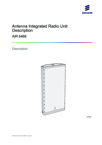
Air handling unitsCHARACTERISTICS OF THE MAIN ATMOSPHERIC POLLUTANTSContinuous suspension particlesTemporal suspension particlesSMOGThick particlesFOGTABACCO SMOKEDRIZZLEATMOSPHERIC DUST AND ASHESVIRUSBACTERIASRAININDUSTRIAL DUSTPOLLENHumanAirFUEL SMOKEVisible under electric microsc.COAL SMOKEVisible under the microscopeELECTROSTATIC FILTRATIONVisible under the human eyeNORMAL FILTRATIONø particles0,1110Drop Speed0,0000350,00350,296CYCLONES10029,61 000MicronsMICRAS395cm/sAIR PURITY CONDITIONS IN CLEAN ROOMSCONDICIONES DE LA PUREZA DEL AIRE EN SALAS LIMPIAS100 00035010 000351 0000,35Particles per cubic foot3 5003,5Particles per litre16TYPETYPE100TYPE*100,05110209 a10003 5 000000035010035510PARTICLE SIZE (Microns)(Micras)* Counts below 10 particles per cubic foot (0.35 per litre) are dubious.Example: admissible particles for a Class 10,000 system:10.000per cubic foot, 0,5 microns.1.200per cubic foot, 1 micron.70per cubic foot, 1 micron.50100
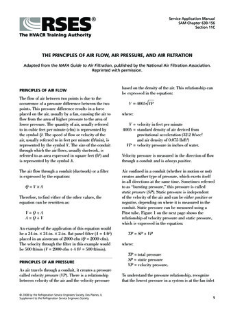
Air handling units Reference: Delhi Metro “DMRC”, Delhi, IndiaThe “Delhi Metro” is a new era in the sphere of mass urban transportation in India. These modernMetro are comfortable, air conditioned and eco-friendly. A revolution in the mass transportationscenario not only in the National Capital Region but the entire country.Products/Solution:Modular air handling unitsAir Distribution ProductsTunnel Ventilation ProductsFire Safety Products17
18 Air handling unitsHeat transfer coilsThe cooling and heating units are composed in theenclosure described above, which contains the tube-andfin heat transfer unit, mounted on a special joint cover.determined by the working width of the interior of theair handling unit and expressed in mm. The depth of theheating/cooling unit is composed of a specific numberof rows of tubes facing the direction of air flow. Thenumber of rows is calculated according to the air flowconditions at the inlet and outlet of the unit, based onthe cooling or heating energy used by the equipment.The number of rows is defined by a number, followed bythe letter “R”.Based on the above, a unit designated as 20T 3R 950means:20 T Height of 20 tubes, equal to 635 mm;3 R Depth of three tubes950 Length of finned coil, in mm.The standardised Air Handling Unit range uses thefollowing heating/cooling units:For air cooling processes, units composed of copper pipesand aluminium fins (Cu/Al) are normally used.At thebottom, the cooling section has a aluminium/stainlesssteel pan for collecting condensation and a small hoseto drain the condensation toward the outside. The panis slightly tilted for easier drainage, in order to preventthe proliferation of harmful bacteria such as Legionellapneumophila.Direct expansion units are also used for cooling. Theseunits can be equipped with one or two manifolds. Forheating processes, the same type of copper/aluminiumunits used for cooling is normally used. If the air mightcontain corrosive chemicals, copper tube and fin (Cu/Cu)units should be used to improve the corrosion resistanceof the equipment. This type of unit is more expensivethan the copper/aluminium unit.This range can be used with any cooling or heating fluidexcept steam, where the length of the finned coil isslightly lower, since collectors must be mounted on bothsides of the unit instead of one side only, as normallydone with other fluids.e deformed under these conditionsdue to excessive expansion of the metal.Heat RecoveryRotating regenerative air-to-air recovery unitSpecially designed to transfer sensitive (temperature)and latent (humidity) heat from the exhaust air to thesupply air.The supply air stops in one of the halves of the heatrecovery unit, while the exhaust air circulates incounterflow through the other half.Electrical heating units can also be installed uponrequest, depending on the customer’s needs.Copper tube and aluminium fin heating/coolingunitsThis class of heating/cooling unit is most commonlyinstalled in air handling units and is composed of a coil ofcopper pipes covered with thin aluminium fins to greatlyincrease the primary heat transfer surface of the tube,due to the large transfer surface of the fins.The front air velocity surface (Afo) expressed in m2 isdetermined by the dimensions (width x height) of the airhandling unit internally.The maximum horizontal length of the finned coil isWhen the impeller turns, the small air flowing channelscomprising the impeller are alternately in contact withclean air and with return air, transmitting heat andmoisture from one circuit to the other.
Air handling units Static recovery unitheat recovery systems: Reduced heating plant power, minimising equipmentsizes in terms of boilers, fuel tank, circulating pumps,heat pipes and heating units. Reduced cooling plant size (compressors andcondensers or cooling towers), circulating pumps, pipegrid and cooling units. Savings in operating powerconsumption for heat and cold generation.Any of the recovery systems mentioned in this sectioncan be installed upon request only, as they are notincluded in the BA standardised range.Designed with air-to-air crossflow to transfer sensitive(temperature) heat; in this type of heat recovery unit, thesupply air is completely separate from the exhaust air, inorder to prevent any type of contamination from one airstream to the other. Heat transfer takes place through the plate separatingthe two streams. Two adjacent plates form a small duct for exhaust orsupply air. The plate-to-plate distance varies, depending on the sizeand efficiency requirements.Run around heat pipeDesigned to transfer sensitive (temperature) heat, usingunits manufactured with copper pipes and aluminium fins(Cu/Al).FansThis section is composed of a centrifugal fan with ananchor bedplate, drive and electric motor or plug-fan.The centrifugal fan motor assembly is mounted onSilentbloc bushings and the discharge outlet is joined tothe opening in the enclosure by means of a flexible fireretardant synthetic seal.This allows the unit to run without external transmissionof the small vibrations normally caused by fan motorassemblies.Centrifugal fanThere are three types of fans that cover all needs: theforward and aerofoil models for low pressures and thebackward for medium and high pressures.The method is simple and economic, as the return airflows through one of the units, heating the water thatcirculates inside and is then exhausted.The outside air flows through the other unit, which heatsthe air while it cools the circulating water, with the latterheated again in the return circuit, creating a continuoussensitive-heat recovery cycle in the air.Forward curve fan.Backward curve fan.Once the fan model is selected, check the respectivebehaviour curve to obtain the unique characteristics.Based on two essential factors (air flow and total staticpressure), the following is obtained: Revolutions per minute Efficiency, in % Input power at the shaft, in kW; Mean sound power level of the octave bands, in dB;In order to ensure proper system operation in winter,facilities with an extremely low outside air temperaturemust use glycol water.Benefits achieved from the installation of any of these Air outlet velocity, in m/s; Dynamic pressure, in mm w.g. Peripheral velocity, in m/s.19
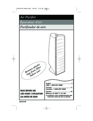
Air handling unitsPlug fanSpecial design: -30/ 60 C.Plug fan built into an acoustically insulated air handlingunit. A plug fan supplies air at the fan section outletwith a low and even air speed. In certain situations itcan, therefore, be an advantage to position air handlingcomponents on the outlet side of the fan.All fans are fully balanced both statically anddynamically. The fan and motor are built on a stable baseframe that is connected to the unit casing with rubbervibration isolators. These are designed for high levels ofvibration absorption.The fan inlet is flexible connected to the unit casing. Thisensures a good vibration absorption.EC fanThe EC fan is equipped with a Single Inlet CentrifugalImpeller with High Efficiency Backward curved bladesand external rotor EC (Electronically Commutated) motor,Plug fan.Single inlet plug fan with open outlet into the airhandling unit. The fan impeller is fitted directly to themotor shaft. This fan type has low sound power levels inthe lower frequencies. Efficiency up to 75%.The motor is supplied with a 1-speed motor. In order toregulate the fan speed to its actual operating point themotor must be fitted with a frequency converter.The frequency converter can continuously control the fanspeed and airflow. Power consumption can be greatlyreduced by operating the fan at lower speed.Operating temperatures:energy optimized for operation without spiral housing forhigh efficiency and favourable acoustic behaviour. Thehigh efficiency backward curved impeller with rotatingdiffuser, made of high performance composite material/ welded aluminum sheet material, with external rotormotor balanced together statically and dynamicallyAREA OF APPLICATIONMost efficient of the centrifugal fansGeneral ventilation/air conditioningMost efficient operating conditions are achieved with maximum flow of 40-50%Mainly large systemsPower is also peaked at the maximum efficiency levelSignificant energy savings in large industrial fresh air systemsEfficiency is slightly lowerGeneral ventilation/air conditioningSimilar efficiency with Aerofoil fanFan should not be operated on the right side of maximumpressureFansEC fan.EFFICIENCYFansBackward CurvedAerofoil FansStandard design: -10/ 40 CForward Curved20Most efficient operating conditions are achieved with maximum f low of 50-60%Lower maximum efficiency than the other centrifugal fansCertain industrial applications where air foil fans might beexposed to corrosion and wearMainly for low pressure ventilation/air conditioning applications
Air handling units according to DIN ISO 1940 Part 1.Panel humidifierThe EC fan is capable of being fitted in horizontalor vertical position in the AHU, depending on theapplication. Inlet cone is provided with a nozzle forvolume flow measurement of the fan.Composed of a standardised enclosure, including astainless steel drip pan at the bottom.SilencersThe baffles of the silencer section are constructed ofnatural galvanized steel sheet, with a peak at the airinlet end to decrease the head loss. The baffles are alsofilled with a sound-insulating material composed offibreglass with an appropriate density. This material isalso heat-resistant and its outer face is protected againstair erosion.There are two options: PA. The sound insulation is protected against erosiondue to air flow by a flame-retardant protective layer.This is the most common approach in ventilation andair conditioning systems. PAM. Similar to PA, but with an additional polyesterfilm coating (Melinex).Used for applications with acidic, alkaline or oilygases, as it can be steam-cleaned.Recommended for hospitals, since bacterial colonyformation is not possible.These two models can be constructed with four lengthsof baffle.HumidifierTwo different types of air humidifiers can be installed inBA air handling units. In both cases, the units are adiabatic humidifiers.The enclosure houses the humidifier panel, which hascrosswise corrugated channels to ensure minimum airresistance as well as a large contact surface betweenthe air and water, thereby releasing moisture into thecirculating air.The top of the panel contains a water manifold, to
6 Air handling units 5.56 11.11 16.67 22.22 27.78 33.33 38.89 44.44 50.00 55.55 m3/h m3/s Systemair has a wide range of air handling units for use in various applications from small office premises to larger