Transcription
SPACE FRAMES --STATIC ANALYSIS
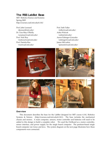
VIBRATION ANALYSIS AND DESIGN OPTINISATIONSTUDIES OF SPACE FRAMESI - STATIC ANALYSISBYS. K. TIWARIA ThesisSubmitted To The Faculty of Graduate Studiesin Partial Fulfilment of the Requirementsfor the Degree ·Master of EngineeringMcMaster UniversityMay,1968
McMASTER UNIVERSITYHamilton Ontario. STEROF ENGINEERING (1968)(Mechanical Engineering)TITLE:Vibration Analysis and Design Optimisation Studiesof Space .FramesAUTHOR:- Static AnalysisSanat Kumar Tiwari, B.Sc. (Banaras Hindu University)B.E. ·(Hons.) (Saugor University)SUPERVISOR:Professor J. N. SiddallNUf·1BER OF PAGES:vii9·108SCOPE AND CONTENT:An oblique four bar structural model with fixed member ends,being the most general building block for space frames, is analysedfor establishing its influence coefficients, using the FiniteElementi' atrix 1ethod.Experimental techniques for measurement of the flexibilityinfluence c.oeffi ci ents of the mode 1 are described.-Experimental results have been compared against analyticalones .ii
ACKNOWLEDGEMENTSIt is a pleasure to the author to be able to record hisgratitude to Professor J. N. Siddall and Dr. M. A. Dokainish fortheir interest, guidance and many valuable suggestions.The author feels indebted to the Department of MechanicalEngineering and the Canadian Armament Research & DevelopmentEstablishment for the opportunity to participate in the project.Further the author wishes to express his appreciation to allwho directly or indirectly offered help at various stages.Finally, the assistance of Mrs. Anne Woodrow in typing themanuscript ts thankfully acknowledgedoiii
TABLE OF CONTENTSLIST OF ILLUSTRATIONSvABSTRACTviINTRODUCTION1THE PHYSICAL MODEL12THEORETICAL ANALYSIS12The Mathematic ModelAnalysis1415EXPERIMENTAL ANALYSIS25RESULTS AND CONCLUSIONS35FIGURES43APPENDICES58II.,Computer ProgrammesAnalytical Flexibility MatrixIII .Experimental Flexibility Matrix85IV.Percentage Error99I.r atiivrx71
LIST OF ILLUSTRATIONSFLO CHARTHISTOGRAMS(Computer Programme)21(Results)37FIGURES431Overall Picture of the Set Up442Details of Displacement Transducer453Details of Ball Joint for Loading Frame454Overall Picture of Angular Measurement Arrangement46Detail of Telescope466Installation of Devise to Eliminate RotationError in Linear Displacement·477Devise to Eliminate Rotation Error in LinearDisplacement Measurements478Discretised Mathematical Model488aModel Dimensions and Material Properties499Top Plate and the Composite Element5010Error in Angular5111Sign Conventions5211 aTenns in Matrix R5312Resolution of Linear Displacement54·5r easurementv
ABSTRACTThis researchp ogrammehas the general objective ofestablishing analytical techniques for analysis of indeterminatespatical frames and shells under dynamic loading, and the designoptimisation of these structures under the constraints of dynamicloading.Although techniques developed should have wideapplicability, emp0asis will be placed, for experimental and .illustrative purposes, on structural configurations common tomachine structures.Recent success of the finite element matrix method andprogress in the field of nonlinear optimisation provide a rationalbasis for the synthesis of space frames, with emphasis on configurations common to mechanical engineering structures.For the initial stage of the project a highly redundant obliquefour bar space frame was selected toinvesti ateinto the nature of·:.Problems involved in the optimisation of generalised space framessubject to dynamic constraints.The present work relates to thest ticanalysis of the frameincluding a theoretical analysis based Qn the finite element approachand experimental determination of the influence coefficients.vi
The average percentage error ·;n actual measurement variesapproximately from four percent for larger flexibility influencecoefficients to about ten percent for smalller ones.Related studies will examine the dynamic analysis of thestructure, and the optimisation prob1emevii
INTRODUCTIONThis research programme has the general objective of establishinganalytical techniques for analysis of indeterminate spatial framesand shells under dynamic loading, and the design optimisation ofthese structures under the constraints of dynamic loading.Althoughtechniques developed should have wide applicability, emphasis willbe placed, for experimental and illustrative purposes, on structuralconfigurations common to machine structures.This present work relates to the first stage of this programmein which the problem. is explored by examining a simple discreteelement space frame with generalized characteristics.Morespecifically, this thesis is concerned with the static analysisof the structure, including a theoretical and experimentaldetermination of influence coefficients and stress-load transfermatrices.Related studies· will examine the dynamic analysis ofthe structure, and.the optimisation problem.discussion reviews· the overall problem.1The following
2Design systhesis essentially is an evolutionary spiral processinvolving a complex feed back interrelating the fields of creativity,past experience and tools of analysis.The role of the designeris to optimise the value of a synthesis on the basis of somecriteria through a balanced exploitation of the evergrowinginformation from all the three fields.The basic techniques andthe criteria of evaluation themselves need refinement from time totime in the light of achievements in the foregoing areas.The process has been marked with a rather slow progress in thefield of mechanical engineering structures, mainly due to theirinherent nature.These have not received the intensiveinvestigation that civil and aerospace engineering configurationshave.Analysis of mechanical engineering structures has perhaps1agged behind because they are. much more di ffi cult to categorisethan in the· other fields where a few highly typical configurationscan berecognised modelled and studied .in a concentrated way. Inaddition, the analytical tools available until lately have hadtheir own limitations.1 ,2These methods can be broadly classified into two divisions,(1) Methods based on exact solution of the differential equationsdescribing the structure.Apart from the difficulties in se-tting up and solving theequations subject often to awkward boundary conditions, in case of
3. complex structures the basic assumptions proved too restrictivefor accurate solution.(2)Approximate methods involving mathematical approximationscan be subclassified into (a)Those based on finite difference procedures.Theseare unsatisfactory in their formulation of boundaryconditions and convergence characteristics, and(b) Those which approximate the stress or displacementdistribution by a series of analytical expressions andhence are unsuited for complex structures.The classical ·analytical tools are thus incapable of providingan integrated approach even for structures of moderate complexity.Hence iti not surprising that the practical design of mechanicalengineering structures has relied more on past practical experiencesupported by rough analytical checks wherever possible, rather thanon the analytical tools.The need for a tool well suited to complex configurations wasmost acute in the aircraft industry where the designer had to workwithin extremely narrow margins of practical expediency3. Theextensive efforts over years by numerous and often isolated workersculminated in the finite element approach which is a major breakthrough from the past.
4Based on structural as against mathematical approximation, themethod essentially seeks to idealise the structure into an assemblyof a finite number of discrete elements connected at a finitenumber of points, and then proceeds to solve for the system responseon an exact mathematical basis.It is the finite connectivitywhich permits a complex continuous structure to be analysed by asystem of algebraic equations and forms the basis of the technique.Although earlier work was restricted to the field of aeronauticalengineering, recently results of applications to nonaeronauticalproblems 4' 5 ' 6 and extensions to three dimensional discrete elements 7have been reported.It is realised that, although the finite element techniqueis still developing, it provides a unified approach to the analysisof any type of structural assembly, from any field and with anycombination of one, two or three dimensional elements of differentcharacteristics 4 It thus provides a reliable analytical toolwhich is a prerequisite for design systhesis.A rather limited amount of work appears to have been done onthe general problem of elastic vibration of structures and theproblem of optimisation under vibrational constraints, althoughtechniques for calculating the natural modes and frequencies oflumped mass spatial structures are fairly well established foressentially beam like aircraft structures, and to a lesser extent
5the rectangular frames of civil engineering.The significanceof rotary inertia in spatial frames does not appear to have9been studied.Archer8 ' has provided two useful new papersin this field and has related it to the finite element stiffnessmatrix technique.Hurty10has developed a method for analysingcomplex structural systems that can be divided into interconnectedcomponents.The concept of optimum design has registered a drastic changesince the advent of high speed digital computers.Ear 1i e r, themagnitude of computation involved acted as a deterent and a feasiblesolutionw s.accepted·-·to handle thein lieu of the optimum.arit metic,With computerssystematic design synthesis has becomea reality.Very many general techniques of optimisation appear in theliterature that might be applied to structural optimisation.Mostpromising are the Direct Search Method first suggested by Hookeand Jeeves and further deve 1oped by Flood and Leon 11 , the r ethodof Successive Linear Approximation due to Griffith and Stewartand the. Random Method of12,Di kinson 13 Minimisation of weight, weight stiffness ratio, cost, volumefor a homogeneous structure, etc. have been suggested as criteriafor optimisation of structures, but mjnimisation of weight appearsto have been accepted as the most satisfactory one even though the
Gminimum weight design is not always the minimum cost design.The optimisation of a statically determinate truss subjectedto single loading is a problem in analysis rather than synthsiseFor strength design, member cross sections are proportioned todevelop maximum allowable stress for the required failure mode.For optimum stiffness design based on minimisation of weightper unit stiffness, stiffness being defined as the reciprocal ofstrainenergy the members should carry stresses proportionalto the square root of the product of the modulus of elasticity andspecific 111eight.The constant of proportionality i's based onstiffness requirements 14For a. given determinate truss under multiple load conditionthe problem essentially remains the same.All the member crosssections carry the maximum allowable stress, based on strengthor stiffness design, at least under one load condition.Theoptimum design has come to be recognised'as a fully stresseddesign.In the case of indeterminatetrusses for a given configuration,applied loading and allowable stress, the cross sectional areaof the members and hence the weight of the structure are functionsof forces in the redundant membersoSved15 has shown analyticallythat under single load conditions the minimum weight structure isalways determinate.
7Using the Lagrange multiplier·technique L C. Schmidt16hasshown that under alternative loads numerous fully stressed designsof an indeterminate truss existoDue to the prohibitive natureof computations involved in arriving at the minimum weight he hassuggested two complementary relaxation methods to arrive at afully stressed design.The beginning of the present decade marked a radical departurein the approach to structural optimisation.It came to be acceptedas a problem in mathematical programming with Schmit17as thepioneer.Utilising the joint force and displacement formulation18of structural analysis as first proposed by Klein , he has optimiseda fixed configuration three bar truss subject to three alternate1oads.He treated it as a problem in nonlinear programming byadopting a modified steepest descent method designated as the methodof alternate steps. On encountering an inequality constraint:. v1hichmust be convex, the earchmoves along a constant weight plane in thefeasible region until the constraint is again contactedoIt thensteps back halfway, and then continues.to move along the steepestslope .On the basis of numerical results he concludes that interms of design parameter space the minimum we.ight design need notbe a fully stressed design lying at the apex of constraint hyperplanes .
8Subsequently19:.20 .1ncollaberation with Mallett and Kicherhe extended the above to the problem of selecting a suitableconfiguration and material for the three bar truss&optimum designs were compileduration byVariouschanging the material or configThe best of all theseone at a time in discrete steps.design was chosen.Dorn et a1 21 have proposed a linear programming method whichselects the optimum combination of configuration and member crosssection from a wide classes of admissible trusses definednumber of admissible joints connected in all possible waysmembers.bybya givenlinearThe optimisation is based on a modified simplex methodcapable of handling large number of equationsQThe results providean interesting study in the behaviour of optima due to change in loadand the height-span ratio of the truss.The configuration remainsthe same for the load for a certain change in height-spanahd thenalters asc continues to change.ratio Thus a continuousspectrum is provided from which the value of a giving the absoluteminimum weight truss and the configuration itself could be selectedGBest 22 has optimised a cantilever box beamdescent'method .It has one unique featureQbythe steepestThe particalderivatives of stress and deflections with respect to the designparameters are calculated by the finite· difference approximationusing the stiffness 'matrix which must be inverted to obtain the
9deflections.To avoid the time ·consuming process of inversionat every step he adopts an interative scheme to obtain the deflections.Only the incremental stiffness matrix for a given change in designparameter is calculated which, in conjunction with the previouslyinverted stiffness matrix, rapidly converges to the required displacements on iterationsoreduce the calculation time.This feature is said to substantiallyConstraints on stresses and deflectionsare handled by a version of tbe reduced gradient method.solution is a maximum stresssolution Hisand thus forced to be on aboundary.The presentation of the structural synthesis as an unconstrainedIt is based onminimisation problem by Schmit and Fox 23 is uniqueQthe method of solving linear simultaneous equations by minimisingthe sum of squares of the residuals to zero.set up for·the equalityco straintsdefining theThis expression isstresses To thisis added penalty terms for violated inequality constraintsg which are.all simple upper and lower bounds.optimised theweight The actual quantity to beis treated as an inequalityconstraint requiring that the weight be less than an arbitrarily defined drawdown \\Ieight The problem is now an unconstrained optimisationproblem solved by a gradient method.It is repeated using progress-ively lower draw-down weights until the optimisation function cannotbe made zero.This indicates that the draw-down w ight is lowerthan the inherent minimum weight.'rhe method thus actually requires
10a series of optimisations.It does not seem too applicableto complex probiems; as the constraints must be expressed explicitlyin order to set up the residualsQThe implicit matrix form ofequality constraints are ruled outQRazani 24 has proposed an unconventional approach using an iterativetechnique ·in which areas are changed by successive increments froman initial feasible solution so that each member is fully stressedin at least one of the several possible load conditions.gives a feasible solution forced to be on a boundaryaThisThe trueminimum. may not be on a boundary if the stress is indeterminate.The gradient projection technique has been successfully adopted25by Brown and Alfredo to optimise a portal frame and a two storeysingle bay frame.The search begins at a feasible starting.pointuntil constraints are encountered&At this point the constrainthypersurfaces are approximated by hyperplanes and gradient of theobjective function is projected on the line of intersection of theseplanes.After a move along the indicated direction a correctionis indicated due to the nonlinearity of the constraint hypersurfacesoThe authors have proposed the use of only one design parameter for amember as variable vJhi le the rest of the parameters for the same memberare expressed as functions of the selected one.As moment ofinertia of the members has a predominant effect on the behaviour ofthestructure of inertia.other. parameters are expressed as functions of momentInspite of this simplification the procedure seems
11too invloved for complex structures.Young and Christiansen14have provided the first known optimalstructural design technique using vibrational constraints usingan iterative technique.Adjustment of the member area to achievea fully stressed design simultaneously with the required resonantfrequency characteristic is the main feature.pin jointed space .truss is includedoAn application to
12THE PHYSICAL MODELFor the first stage of the project it was decided to examinea simple but highly redundant space frame with generalisedcharacteristics. vithAn oblique four bar frame without symmetry andfixed member ends illustrated in Figure 1 "asselected.Theobliquity of the bars ensured assymmetry of static and dynamicresponse.The four bars are welded at the base to a half inchthick aluminum alloy plate atinch square spacing.a 24The topends of the bars are brought close together and welded to anotherhalf an inch thick aluminum plate at a square spacing of 2.5 inches.It is extremely important for the accuracy of the results thatdeflection of the bars at the ends fixed to the base plate are smallas compared to the relative displacement between points on thestructure due to applied load.To ensure this the base plate isbolted firmly around each leg of the structure between 1.25 inchesthick steel plates.The point at which the external loads areapplied is located at the centre of the top plate.THEORETICAL ANALYSISThe decision was made to first examine the problem usingthe finite element - matrix approach.by this method is well established.Static analysis of structuresDuring the earlier stages ofdevelopment the literature v1as in the form of a number of shortindividual publications marked by variety of notations and seemingly
13different approaches to the same basic technique, often appliedto specific situationsQThe most oft quoted work as the firstcomprehensive presentation of the subject is by Argyris and Kelsey26.Results of a more recent survey of the finite element method with avie\-J to unifying the techniques and classifying the approaches toderivation of element properties has been presented by Gallagheret al 27 . k1ew1cz. . 30 1s. par t 1cu. 1ar 1yThe very recent boo k by z1encomprehensive and useful.The finite element analysis of a general structure consists of4three distinct phases (1)Structural idealisation wherein the original structureis represented as an assembly of discrete elements,(2)Evaluation of element properties,(3)Analysis of the discretised structure.Phase 1 introduces into the anlaysis the first of the approximations.Judgement is required to provide a discretisation capableof reasonably accurate results but in general is not a difficultprob 1em.The success of the method and its extension to new areas dependalmost entirely on the second phase.It is therefore not surprisingthat the derivation of element properties of various shapes hasreceived such wide attention.TvJo .levels of approximations areinvolved in the development of these properties - assumptions about
14the essential element behaviour and secondly representation ofdistributed stress and displacements in terms of nodal forces anddisplacements 27 .The third phase like any other method of structural analysisseeks to satisfy the conditions of equilibrium, compatibility andforce displacementrelationship simultaneously.Depending on\'lhether compatibility or equilibrium equations are utilised first,the methods can be classified into the equilibrium or displacementmethod and the compatibility or force method.The proceduraldetails of these methods are readily available in a number of excellent.recent pub 11cat1ons28 29,30. The Mathematical Model:The analytical procedure uses two mathematical models - static.and dynamic.model.The later is usually an extension of the staticThe accuracy of analytical dynamic response depends on thenumber of nodes selected for formulation of the mass matrix.Theamount of experimental work involved in determination of the influencecoefficients, however, increases in proportion to the number of nodes.As a compromise each member was discretised into three equal lenghts.For the static model the top plate was treated as rigid due toits relatively small size and comparativelyl rgethickness.It \-Jaside ali sed into four rigid bars each jo"i n·i ng the centre of the topplate to the point of intersection of a member axis with the plate.
15The combination of the rigid element and the corresponding flexiblemember element was treated as an integral finite element, and theelement property was formulated as such.The static mathematical model thus consisted ofelements.t tJelvediscreteThe arrangement of the elements in the physicalmodel is shown in Figure 8 Analysis:The analysis was subject to the usual limitations of smalldisplacements and linearity of stress-strain and force-displacementrelationshipsoThe weight of the structural elements was neglectedas being small compared to their load capacity.In evaluating theelement characteristie:.matrix the deflection due to shear was neglectedThe dfsplacement method was adopted as it is simple andstrai ghtfonvard to programme.The basic assumptions used in this method are (1)Boundary displacements of adjacent elements are mutuallycompatiblell(2)Stresses in the elements due to the boundary displacements areequilibrated by a set of forces at the element boundary inthe direction of the displacements, and(3)Element forces are related tb the corresponding elementdisplacements by an element stiffness matrix expressed by
16the matrix equatione{ pi}where[kil{Si}:.(1){ Pl·}is the element boundary forces vector,[ ki]is the element stiffness matrix,{ b }is the element boundary displacement.lrefers to the element numberFor all the elements treated as unconnected Equation (1)vJri tten as\·Jhere { P}t P)vector [k]can be\S"}(2)r P } t .Jand n is the total number ofPVIIelements in the structureAlso[ ] S·t:d-jand.{ s}1b,JWhen elements are connected together to form a structureEquations (l)cancombined into asingl . -.:.relationship.(3){ F}\vhere{F}is the structDral joint forces vectortj ]is the structural assembly stiffness matrix
17is the structural joint displacement vector.andElement boundaries have the same displacements as the structuraljoints to which they are connected if both are referred to a commoncoordinate system.This can be expressedby(4)where [ ] is the displacement transformation matrix.of zero and one as elements.It consistsIf the displacements are referred todifferent coordinate systems the relation (4)still holds bute 1ements of rna tri x [f.'] contain e1ements of the coordinate transformation matrix.The work done in loading the structure by theapplied loads{F} must be equal to the internal energy.Thereforefrom Equation (2) and (3)2{SiH P}2{oT}[ J{S} 2But{bT\ l ] [ ]{u}{u.T}[ T](5)(6)Therefore or{ll}[ T]f ] [ 3]{ u}[ -r][ V .] [fl { u.1(7)
18Comparing Equations (3) and (7)we see that[ K](8)The matrix product[ ] is a sparsely populated matri xQindicated by Equation (8)therefore,·can be a very time consuming11However, the structuralstep particularly for large structures.stiffness matrix[ ]can be generated· directly by assembling theelement stiffness matrices already transformed into the structuralcoordinate system.This method has come to be known as the3: 33Direct Stiffness MethodThe assumption of rigidity of the plate and the selection of thedisplacement method precluded the choice of more than one node onthe top plate.matrix willIf more than one node is selected the flexibilityhav dependent displacement rows.the stiffness matrix, does not exist28Hence its inverse,Imposition of a one nodecondition dictated the use of integral elements made up of flexibleand rigid components.The combination shown in Figure (8) wasachieved by the transformation of the stiffness matrix of the flexiblecomponent BC by the equilibrium matrix of the rigid component CDaccording to the expressions given beleN3J 32.-[K,,Jec[l t2.] BD-[K12) ec. [[ l/\22) BD-[1-\:o] [,, K '-2 j[ ul- BD-\'THco]sc [ i1 (9)f
19whereBDis the composite element,[ H c 0 ] i s the eq ui 1i bri urn rna t ri x of CD·K K etc. are 6 x 6 submatrices of the element stiffnesses .?Ba.in system coordinates.The following computer programmes were used in the analysis.Subroutine TRANF:With position coordinates of member ends and components of aunit vector along the member Y axis as the input, the subroutinecalculates the coordinate transformation matrix and checks it forIf this condition is not satisfied execution isorthogonality.terminated after printing out an error message.Subrountine STIFCO:Area of cross section and moment of inertia are read in alongwith the elasticmodulii Depending upon the value of an index,the output is a stiffness matrix inmembe ·.coordinatesor in systemcoordinates, or is the stiffness matrix of a composite element.Subroutine TRANQL:This subroutine transforms the stiffness matrix by the equilibriummatrix to provide the stiffness matrix of the composite element.In
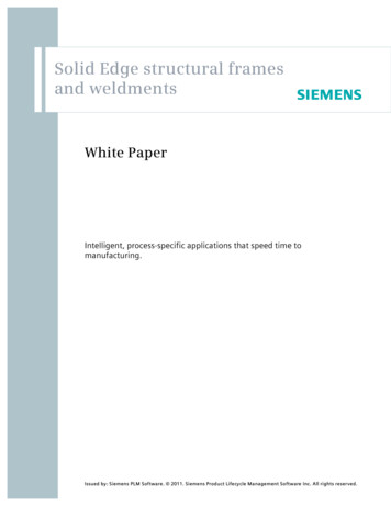
20case of shortage of storage space it can be used to provide the12 x 12 stiffness matrix of a free element from the 6 x 6 stiffnessmatrix of the same element when fixed at one end.Subroutine ASSEMGL:Once the stiffness matrix of all the elements has been workedout the subroutine can assemble the structural stiffness matrix.Main Programme:The main programme utilises the subroutines to obtain thestructural stiffness matrix, inverts it to supply the flexibilitymatrix, and checks the validity of inversionThe subroutine approach provides the more flexible and moregeneralprogra mes.The scheme of computations is indicated as follows on the nextpage.
b.II - :.;:.C{H t CS TE- TR NQLI ,----·'E.LE.ME.NTASEMBL.'CHECK'- ------ --------- b--------- 1. S .T.n. 1- O!JT! 'UT :- , uc
22For optimisation analysis a relationship between external loadsand resultant forces on member ends was required.loads were to act at the apex of the structure.The externalHence only oneThe structure was thereforenode at the top plate was required.idealised into four flexible members integral with a short rigidFurther the lower ends ofelement contributed by the top plate.all the four members are fixed to the foundation, hence the structuralassembly matrix was a superimposition of submatricescomposite element.for eachThe structural stiffness matrixcan beexpressed as [ K]-n. L . [ HiJ [Ti}[ 2·1 LTi}[ Hi']-T( 10)i awhere [ 2 2) is the element stiffness submatrix in member coordinates6X6,[ T]is the transformation matrix to system coordinate, 6 x 6,[ H Ji s the eq ui 1i b ri um rna t r i x , 6 x 6.2is the member numberIf the displacements at the node are given by {load by {u.}and· exte rna 1f}- [ ]tF}then6.· 6The member end disp 1acements . {d.} re( ll )6)'\given by{d\}where { ]is a transformation matrix defined by expression (4)( 12)
23For the present structure it is a column vector of four 6 x 6 indentitymatrices.Substituting (ll}in(l2) gives[ (3] [ - ] { F}2.4 6( 13)6)'. G.r.GDue to the special nature of [ (3 J for the present case we can\vri te{ d i \:( 14). [ K . e] { F}6)(. 6)(.G6,.J\vhere fdl}is the end displacement of the :/A member in system coordinates.Transforming these displac ments to the ends of the flexible component( 15)vJheret d. if\ representsthe di sp 1a cement at the f1 exi b1e end of theit -J member, connected to the rigid part.member coordinates to givet d. if }--m Transforming { di-5}to{ dif "ryl. we have[1 { Ji }TiSubstituting (14) and (15) into (16)w (16)get( 17)Forces{ Pa:} m at the ·free fl exi b1e end of each e 1ement are given by.{ Pi}mSubstituting (9) in (10)-[ u] { o\if} m( 18)
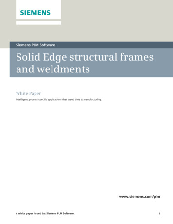
24T'J.6')(. 6 6The stresses in the member can be obtaineda genera 1 transformation matrix [S icolumn vector of axial stressS '-yzands. zi '":;.ti&i'bbyR ] ( 19)transformingLeti Si}be aand transverse shear stressesv-1here xvz. refer to member coordinates.-{ s;}Then- [ k 2 &.] [ T i] ( Hi] ( K] { F} { P 2 }. '' \. by-a1 { P·}lm[ R3xG)f.l6(20).)(.aSubstituting ( 19) into (20) gives [ R] [ i'(G . ][ "T i1[ H Jr' [ K-1 ] -::tG,6'li'tG6x 6 6{ "F \(21) -.r.\The exact nature of e1ements, in [ R] wi 11 depend on the membercross-section.byFor a hollow circular cross-section it is giventhe following matrix.'.A0l·R CosSI:z.6-· MA:tI-zSa-n·tl R SLV\ 9· 0 SineeC)Iy l .y si'Y\MAz·CoseJ:z twhere the significance.,. R.@ St't, Iy·t0r MAy (o eRoCoseIy ·t.and-l-yR 9 cos 0l;z.0l(22)0IIJ'o.sign convention for the terms in matrixR are shown in Figures 11 and lla.
25EXPERIMENTAL ANALYSISBoth static and dynamic analysis may require the stiffnessor the flex
An oblique four bar structural model with fixed member ends, being the most general building block for space frames, is analysed for establishing its influence coefficients, using the Finite . of structural analysis as first proposed by Klein 18, he has optimised a fixed configuration three bar truss subject to three alternate 1 oads .