Transcription
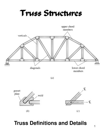
Truss StructuresTruss Definitions and Details1
Truss: Mimic Beam Behavior2
Bridge Truss Details3
Framing of a Roof Supported Truss4
Common Roof Trusses5
6
Buckling Calculations2π EI weakPcr 2( kL) buckling forcek effective length factork 1 for an ideal truss member7
Types of TrussesBasic Truss Element three member triangular trussSimple Trusses – composed ofbasic truss elementsm 3 2(j - 3) 2j - 3for a simple trussm total number of membersj total number of joints8
Simple Truss9
Compound Trusses –constructed by connecting twoor more simple trusses to forma single rigid body10
Complex Trusses – truss that isneither simple nor compound11
Analysis of TrussesThe analysis of trusses is usuallybased on the following simplifyingassumptions: The centroidal axis of eachmember coincides with the lineconnecting the centers of theadjacent members and themembers only carry axial force. All members are connectedonly at their ends by frictionlesshinges in plane trusses. All loads and support reactionsare applied only at the joints.12
The reason for making theseassumptions is to obtain an idealtruss, i.e., a truss whose members are subjected only to axialforces.Primary Forces member axialforces determined from theanalysis of an ideal trussSecondary Forces deviationsfrom the idealized forces, i.e.,shear and bending forces in atruss member.Our focus will be on primaryforces. If large secondary forcesare anticipated, the truss should13be analyzed as a frame.
Method of JointsMethod of Joints - the axialforces in the members of astatically determinate truss aredetermined by considering theequilibrium of its joints.Tensile (T) axial member force isindicated on the joint by an arrowpulling away from the joint.Compressive (C) axial memberforce is indicated by an arrowpushing toward the joint.14
15
16
Truss Solution17
Zero Force Members:(a) If only two noncollinearmembers are connected to ajoint that has no external loadsor reactions applied to it, thenthe force in both members iszero.(b) If three members, two ofwhich are collinear, areconnected to a joint that has noexternal loads or reactionsapplied to it, then the force inthe member that is notcollinear is zero.18
θθZero Force Members19
Zero Member ForceCalculationsFigure (a): Fy 0 FAB cos θ FAB 000 FAC FAB sin θ Fx FAC 0Figure (b): Fy 0 FAC cos θ FAC 020
Truss analysis iseasier if one canfirst visually identify zero forcemembers21
Method of SectionsThe method of sections enablesone to determine forces inspecific truss members directly.Method of Sections involves cutting the truss intotwo portions (free body diagrams,FBD) by passing an imaginarysection through the memberswhose forces are desired.Desired member forces aredetermined by consideringequilibrium of one of the two FBDof the truss.22
Method of sections can be usedto determine three unknownmember forces per FBD since allthree equilibrium equations canbe used.Method of Sections Example23
FBC FHG FHC 24
Statics Principle ofTransmissibility25
Transmissibility principleof statics states that aforce can be applied at anypoint on its line of actionwithout a change in theexternal effects26
FBC FGF 27
FJC FJF 28
K-Truss Solution29
Determinacy and StabilityInternal Stability number and arrangement ofmembers is such that the trussdoes not change its shape whendetached from the supports.External Instability instability due to insufficientnumber or arrangement ofexternal supports.30
Internal Stabilitym 2j – 3 truss is internally unstablem 2j – 3 truss is internally stableprovided it is geometricallystablem total number of membersj total number of jointsGeometric stability in the secondcondition requires that themembers be properly arranged.31
Statically Determinate Truss if all the forces in all its members as well as all the externalreactions can be determined byusing the equations ofequilibrium.Statically Indeterminate Truss if all the forces in all its members as well as all the externalreactions cannot be determinedby using the equations of equilibrium.External Indeterminacy excess number of supportreactions32
Internal Indeterminacy excess number of membersRedundants excess members and reactionsNumber of redundants defines thedegree of static indeterminacy ISummarym R 2j statically unstable trussm R 2j statically determinate trussm R 2j statically indeterminate 33truss
The first condition is alwaystrue.But, the last two conditions aretrue if and only if the truss isgeometrically stable.The analysis of unstabletrusses will always lead toinconsistent, indeterminate, orinfinite results.34
Truss Determinacy Calculations35
Truss Determinacy Calculations36
Equations of Condition:Plane Trusses37
Bridge Truss Details 3. 4 Framing of a Roof Supported Truss. Common Roof Trusses 5. 6. 7 B