Transcription
III. Three-Phase Circuits
Three-Phase SystemsAlmost all electric power generation and most of the power transmissionin the world is in the form of three-phase AC circuits. A three-phase ACsystem consists of three-phase generators, transmission lines, and loads.There are two major advantages of three-phase systems over a singlephase system:a) More power per kilogram of metal form a three-phase machine;b) Power delivered to a three-phase load is constant at all time,instead of pulsing as it does in a single-phase system.The first three-phase electrical system was patented in 1882 by JohnHopkinson - British physicist, electrical engineer, Fellow of the RoyalSociety.
1. Generation of three-phase voltagesand currentsA three-phase generatorconsists of three singlephase generators withvoltages of equalamplitudes and phasedifferences of 120 .
Each of three-phase generators canbe connected to one of threeidentical loads.This way the system would consistof three single-phase circuitsdiffering in phase angle by 120 .The current flowing to each loadcan be found asVI Z
Therefore, the currents flowing in each phase areV 00IA I Z V 1200 I 120 IB Z V 2400 I 240 IA Z
We can connect the negative (ground) ends of thethree single-phase generators and loads together, sothey share the common return line (neutral).
The current flowing through a neutral can be found asIN I A IB IC I I 1200 I 2400 I cos( ) jI sin( ) I cos( 1200 ) jI sin( 1200 ) I cos( 2400 ) jI sin( 2400 ) I cos( ) cos( 1200 ) cos( 2400 ) jI sin( ) sin( 1200 ) sin( 2400 ) I cos( ) cos( )cos(1200 ) sin( )sin(1200 ) cos( )cos(2400 ) sin( )sin(2400 ) jI sin( ) sin( )cos(1200 ) cos( )sin(1200 ) sin( )cos(2400 ) cos( )sin(2400 ) which is simplified to be 1313sin( ) cos( ) sin( ) I N I cos( ) cos( ) 2222 1313cos( ) sin( ) cos( ) jI sin( ) sin( ) 2222 0
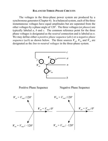
So, as long as the three loads are equal, the return current in the neutral is zero!Such three-phase power systems (equal magnitude, phase differences of 120 ,identical loads) are called balanced.In a balanced system, the neutral is unnecessary!Phase Sequence is the order in which the voltages in the individual phases peak.abcacb
2. Connection TypesThere are two types of connections in three-phase circuits:Y (Wye) and Δ (Delta)Each generator and each load can be either Y- or Δ-connected. Any number ofY- and Δ-connected elements may be mixed in a power system.Phase quantities – voltages and currents in a given phase.Line quantities – voltages between the lines and currents in the lines connectedto the generators.
a) Y-connectionAssuminga resistiveload
The current in any line is the same as the current in the corresponding phase.I L I Voltages are:Vab Va Vb 3V 13 33V V jV V 0 V 120 V V j22 2 231 j 3V 30022 0Vab 3V 30 0Vbc 3V 90 Vca 3V 210
Magnitudes of the line-to-line voltages and the line-to-neutral voltages arerelated as:VLL 3V In addition, the line-to-linevoltages are shifted by 30 with respect to the phasevoltages.In a connection with abcsequence, the voltage of aline leads the phase voltageby 30 as shown in the figure.
b) Δ-connectionAssuming aresistive load Vab V 00I ab I 00Vbc V 1200I bc I 1200Vca V 2400I ca I 2400
Line-to-line voltage magnitudes are the same as the phase voltages.VLL V Currents are: 13 I a I ab I ca I 0 I 240 I I jI 22 3331 I j j 3I 300I 3I 222 20I a 3 I 30 0I b 3 I 150 I c 3 I 270
Magnitudes of the line and phase currents are related as:I L 3 I In addition, the line currentsare shifted by 30 withrespect to the phase currents.For the connections with theabc phase sequences, thecurrent of a line lags thecorresponding phase current by30 as shwon in the figure.
Wye (Y) Connected LoadDelta (Δ) Connected Load
Practical UseWhat do you want to use in practice?[Most common usage] Δ-connected loads are most common to allow easy addition andremoval of loads in each phase Y-connected sources are most common to avoid circulating currentswhen there is a small imbalance.
c) Power relationshipFor a balanced Y-connected load with the impedance Z Z and phasevoltages as:van (t ) 2V sin tvbn (t ) 2V sin( t 1200 )vcn (t ) 2V sin( t 2400 )The currents can be found as:ia (t ) 2 I sin( t )ib (t ) 2 I sin( t 1200 )ic (t ) 2 I sin( t 2400 )
The instantaneous power is:p (t ) v(t )i (t )Therefore, the instantaneous power supplied toeach phase is:pa (t ) van (t )ia (t ) 2VI sin( t ) sin( t )pb (t ) vbn (t )ib (t ) 2VI sin( t 1200 ) sin( t 1200 )pc (t ) vcn (t )ic (t ) 2VI sin( t 2400 ) sin( t 2400 )Simplify the above equations using sin sin pa (t ) VI cos cos(2 t ) pb (t ) VI cos cos(2 t 2400 ) pc (t ) VI cos cos(2 t 4800 ) 1 cos( ) cos( ) 2
The total power on the load is given byptot (t ) pa (t ) pb (t ) pc (t ) 3VI cos The pulsing components cancel each other because of 120 phase shifts, sothe total power on the load is constant.The figure shows:a) The instantaneous powerin each phase.b) The total power suppliedto the load (which isconstant)
Phase quantities in each phase of a Y- or Δ-connection.Real Power:P 3V I cos 3I 2 Z cos Reactive Power:Q 3V I sin 3I 2 Z sin Apparent Power:S 3V I 3I 2 ZNOTE: These equations are valid for balanced loads only.
Deriving line quantities of a Y-connection.Power consumed by a load: P 3V I cos since for this loadthereforeFinallyI L I and VLL 3V P 3VLLI L cos 3P 3VLL I L cos NOTE: These equations are valid for balanced loads only.
Deriving line quantities of a Δ-connection.Power consumed by a load: P 3V I cos since for this load I L 3I and VLL V thereforeFinallyP 3VLLI L cos 3P 3VLL I L cos Same as for a Y-connected load!NOTE: These equations are valid for balanced loads only.
Line quantities for a Y- or Δ-connection.Real Power:P 3VLL I L cos Reactive Power:Q 3VLL I L sin Apparent Power:S 3VLL I LReminder: is the load (or impedance) angle, i.e. the angle between thephase voltage and the phase current.NOTE: These equations are valid for balanced loads only.
d) Analysis of balanced systemsA Δ-connected circuit can be analyzed via the transform of impedances by the Y-Δtransform. For a balanced load, it states that a Δ-connected load consisting of threeequal impedances Z is equivalent to a Y-connected load with the impedances Z/3.This equivalence implies that the voltages, currents, and powers supplied to bothloads would be the same.
Ex. For a 208-V three-phase ideally balanced system shown below,Find:a) The magnitude of the line current ILb) The magnitude of the load’s line and phase voltages VLL and V L;c) The real, reactive, and the apparent powers consumed by the load;d) The power factor of the load.
Both, the generator and the load are Yconnected, therefore, it’s easy toconstruct a per-phase equivalent circuit.a) Phase current:V120 00120 00120 00IL 7.94 37.10 A0Z L Z load (0.06 j 0.12) (12 j 9) 12.06 j 9.12 15.12 37.1b) Phase voltage over the load:V L I L Z L (7.94 37.10 )(12 j 9) (7.94 37.10 )(15 36.90 ) 119.1 0.20 Vand the maignitude of the line voltage on the load:VLL 3V L 206.3 V
c) The real power consumed by the load:Pload 3V I cos 3 119.1 7.94 cos 36.90 2270 WThe reactive power consumed by the load:Qload 3V I sin 3 119.1 7.94sin 36.90 1702 varThe apparent power consumed by the load:Sload 3V I 3 119.1 7.94 2839 VAd) The load power factor:PFload cos cos 36.90 0.8 lagging
e) One-line diagramsSince, in a balanced system, threephases are similar except of the 120 phase shift, power systems arefrequently represented by a singleline showing all three phases of thereal system.This is a one-line diagram.Such diagrams usually include all themajor components of a powersystem: generators, transformers,transmission lines, loads.
If we can neglect the impedance of the transmission line, an importantsimplification in the power calculation is possible If the generator voltage in the system is known, then we can find the currentand power factor at any point in the system as follows:1.2.3.4.5.The line voltages at the generator and theloads will be identical since the line islossless.Real and reactive powers on each load.The total real and reactive powers suppliedto all loads from the point examined.The system power factor at that point usingthe power triangle relationship.Line and phase currents at that point.We can treat the line voltage as constant and use the power triangle method toquickly calculate the effect of adding a load on the overall system and power factor.
2. Connection Types There are two types of connections in three-phase circuits: Y (Wye) and Δ(Delta) Each generator and each load can be either Y-or Δ-connected.Any number of Y- and Δ-connected elements may be mixed in a power system. Phase quantities - voltages and currents in a given phase. Line quantities - voltages between the lines and currents in the lines connected