Transcription
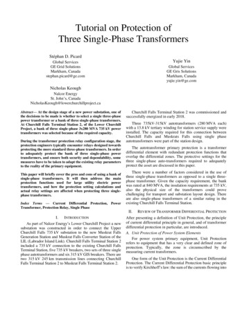
BALANCED THREE-PHASE CIRCUITSThe voltages in the three-phase power system are produced by asynchronous generator (Chapter 4). In a balanced system, each of the threeinstantaneous voltages have equal amplitudes but are separated from theother voltages by a phase angle of 120o. The three voltages (or phases) aretypically labeled a, b and c. The common reference point for the threephase voltages is designated as the neutral connection and is labeled as n.We may define either a positive phase sequence (abc) or a negative phasesequence (acb) as shown below. The three sources Van, Vbn and Vcn aredesignated as the line-to-neutral voltages in the three-phase system.
LINE-TO-LINE VOLTAGESAn alternative way of defining the voltages in a balanced three-phasesystem is to define the voltage differences between the phases. Thesevoltages are designated as line-to-line voltages. The line-to-line voltagescan be expressed in terms of the line-to-neutral voltages by applyingKirchoff’s voltage law to the generator circuit, which yieldsInserting the line-to-neutral voltages for a positive phase sequence into theline-to-line equations yields
If we compare the line-to-neutral voltages with the line-to-line voltages, wefind the following relationships,Line-to-neutral voltagesLine-to-line voltages
Line-to-line voltages in terms of line-to-neutral voltagesThe equations above show that the magnitudes of the line-to-line voltages3in a balanced three-phase system with a positive phase sequence are %× the corresponding line-to-neutral voltages and lead these voltages by30o.
THREE-PHASE CONNECTIONSThe sources and loads in a three-phase system can each be connectedin either a wye (Y) or delta ()) configuration. Note that the wyeconnections are line-to-neutral while the delta connections are line-to-linewith no neutral. Also note the convention on the node designations(lowercase letters at the source connections and uppercase letters at the loadconnections).SourcesWye sourceDelta sourceLoadsWye loadDelta load
BALANCED WYE-WYE CONNECTIONThe balanced three-phase wye-wye connection is shown below. Notethat the line impedance for each of the individual phases in included in thecircuit. The line impedances are assumed to be equal for all three phases.The line currents (IaA, IbB and IcC) are designated according to thesource/load node naming convention. The source current, line current, andload current are all one in the same current for a given phase in a wye-wyeconnection.Wye sourceWye loadAssuming a positive phase sequence, the application of Kirchoff’s voltagelaw around each phase giveswhere Ztotal is the total impedance in each phase and 2Z is the phase angleassociated with the total phase impedance. The preceding equations can besolved for the line currents.
Line CurrentsLine-to-neutral voltagesNote that the line current magnitudes are equal and each line current lagsthe respective line-to-neutral voltage by the impedance phase angle 2Z.Thus, the balanced voltages yield balanced currents. The phasor diagramfor the line currents and the line-to-neutral voltages is shown below. If welay the line-to-neutral voltage phasors end to end, they form a closedtriangle (the same property is true for the line currents). The closed triangleshows that the sum of these phasors is zero.
The fact that the line currents sum to zero in the balanced wye-wyeconnection shows that the neutral current In is zero in this balanced system.Thus, the impedance of the neutral is immaterial to the performance of thecircuit under balanced conditions. However, any imbalance in the system(loads, line impedances, source variations, etc.) will produce a non-zeroneutral current.In any balanced three-phase system (balanced voltages, balanced lineand load impedances), the resulting currents are balanced. Thus, there isno real need to analyze all three phases. We may analyze one phase todetermine its current, and infer the currents in the other phases based on asimple balanced phase shift (120o phase difference between any two linecurrents). This technique is known as the per phase analysis.Example (Per phase analysis)A wye-wye balanced three-phase system with a phase voltage of 120V-rms (positive phase sequence) has a line impedance of Zline (1 j1) Sand load impedance of ZY (20 j10) S. Determine the phasor line currents(IaA, IbB, IcC) and the phasor load voltages (VAN, VBN, VCN).Analyze the a-phase only.
To determine the b phase responses, subtract 120o from the angle of the aphase results.To determine the c phase responses, subtract 240o (add 120o) to the angleof the a phase results.
INSTANTANEOUS THREE-PHASE POWERIn a balanced wye-wye three-phase system, we have found that theline currents and load voltages are balanced (equal magnitudes, phaseangles at 120o intervals). Thus, the rms phasor line currents may be writtenin general form aswhere we have assumed a positive phase sequence. The resulting phasorload voltages can be written in terms of the phasor line currents asThe corresponding instantaneous line currents and load voltages are
The total instantaneous power delivered to the three-phase load iswhere the three terms represent the instantaneous power in the individualloads associated with the three phases. Inserting the instantaneous loadvoltages and line currents givesThe cosine products in the equation above can be rewritten using thetrigonometric identity used in the single phase power derivation:The instantaneous power then becomesThe three double frequency terms in the instantaneous power expressionadd to zero according to the following trigonometric identity:The instantaneous power in the balanced three-phase load reduces to
Note that the balanced three-phase load instantaneous power isconstant and equal to three times the average power in one phase. Thetime-invariant characteristic of the three-phase instantaneous power is incontrast to that of a single-phase system where the instantaneous power wasshown to oscillate at twice the system frequency. The constant nature ofthe three-phase instantaneous power (smooth power delivery) is ofparticular importance in three-phase motors. The mechanical shaft torqueis constant and vibration is minimized.The concept of complex power can be extended to a balanced threephase system by defining the three-phase complex power delivered to thewye load aswhere Vload and Iline are the load voltage and line current phasors for anindividual phase of the three-phase system with a wye-connected load.Inserting the voltage and current phasors into the complex three-phasepower equation givesThus, the apparent, real and reactive power components in a three-phasewye load are
Note that the preceding equations are specialized for wye loads. Amore general way of writing the complex power for any type of three-phaseload iswhereWye loadDelta loadVloadLine-to-neutral voltage (VAN)Line-to-line voltage (VAB)IloadLine current (IaA)Load current (IAB)S3N 3VAN IaA*S3N 3VAB IAB*The concepts of power factor and the complex power triangle can alsobe extended to a balanced three phase power system without loss ofgenerality. The three-phase power factor is defined by the same singlephase equationsince the relative angle between the voltage and current is equal in all threephases of a balanced three-phase system. The three-phase complex powertriangle is identical to the single-phase power triangle with the apparent,real and reactive powers replaced by the corresponding three-phase values.
THREE-PHASE CONNECTIONS INVOLVING DELTA SOURCES OR LOADSIn addition to the wye-wye three-phase connection, there are threeother possible configurations of wye and delta sources and loads.Delta-Delta ConnectionWye-Delta Connection
Delta-Wye ConnectionThe most efficient way to handle three-phase circuits containing deltasources and/or loads is to transform all delta connections into wyeconnections.Delta-Wye Source TransformationGiven that a delta source is defined in terms of line-to-line voltages whilethe wye source is defined in terms of line-to-neutral voltages, we can usethe previously determined relationship between line-to-line voltages andline-to-neutral voltages to perform the transformation.
Thus, line-to-neutral voltages in a wye-connected source that are equivalentto the line-to-line voltages in the delta-connected source areThus, we simply divide the appropriate line-to-line voltage in the delta3 and subtract 30o from its phase angle to find thesource by %&corresponding line-to-neutral voltages for the wye source.Example (Wye-Delta source transformation)Given a delta-connected source with the following rms voltages:3 120).determine the equivalent wye-connected source (208/%&Y
Delta Source - Source Current and Line Current RelationshipThe delta source line currents(IaA, IbB, IcC) are related to thecorresponding source currents (I ba,Icb, Iac) according to Kirchoff’scurrent law.Assuming a balanced three-phase system with source currents defined bythe resulting phasor diagram relating the source and line currents is shownbelow.
The phasor diagram shows that the source currents in a delta source lead3 times the magnitude.the line currents by 30o and are 1/%&Summary: Delta Source (I’s, V’s) in terms of Wye Source (I’s, V’s)
Delta Load - Load Current and Line Current RelationshipThe line currents in the delta-connected load (IaA, IbB, IcC) are related to thecorresponding delta load currents (IAB, IBC, ICA) according to Kirchoff’scurrent law.Given a balanced three-phase system, the currents flowing into the deltaconnected load can be defined byThe resulting phasor diagram relating the line currents to the deltaconnected load currents follows the same pattern as the delta-connectedsource.
The phasor diagram shows that the load currents in a delta load lead the3 times the magnitude.line currents by 30o and are 1/%&
Wye Load - Line-to-line Voltage and Load Voltage RelationshipNote that the load voltages in a wye-connected load are the line-to-neutralvoltages at the load. The line-to-line voltages of a wye-connected load arerelated to the line-to-neutral voltages byFor a balanced three-phase system, the line-to-neutral voltages may bewritten asThe phasor diagram relating the line-to-line voltages to the load voltagesis shown below.
The load voltages and the line-to-line voltages in a wye-connected load arerelated by
Delta-Wye Load TransformationA delta-connected three-phase load can be replaced by an equivalentwye-connected load if the two loads are equivalent (draw the same linecurrents from the three-phase source). Note that the line-to-line voltagesat the delta-connected load are the load voltages. The a phase line currentsfor the wye and delta loads are defined byDelta LoadWye LoadThe line currents are equal ifThe same results are found for the other two line currents. Thus, a deltaconnected load can be replaced by a wye-connected load with one-third theimpedance per phase.
Example (Delta-load transformation, three-phase power)A balanced 120 V-rms wye-connected three-phase source withpositive phase sequence is connected to two balanced three-phase loadsconnected in parallel. Load #1 is wye-connected with ZY1 (30 j40) Sand Load #2 is delta-connected with Z)2 (60 ! j45) S. The lineimpedance per phase is Zline (2 j4) S. Determine (a.) the per phase linecurrent (b.) the total real and reactive power drawn from the source (c.) theper phase line-to-neutral voltage across the parallel load (d.) the per phaseload current in the wye and delta loads and (e.) the total real and reactivethree-phase power delivered to each load and the line.Transforming the delta-connected load #2 into a wye-connected load gives
(a.) The load impedance in the per phase equivalent circuit is the parallelcombination of the two wye load impedances.The total impedance seen by the phase a source voltage isThe resulting phase a line current is(b.) The total complex power supplied by the three-phase source is
(c.) The per phase line-to-neutral voltage across the parallel load is(d.) The per phase load currents in the two wye-connected loads areTo determine the load current in the original delta-connected load, weutilize the relationship between the line and load currents in a deltaconnected load.The load current in the wye-connected load #2 represents theequivalent line current for the original delta-connected load #2. Thus,the load current in the original delta-connected load #2 is(e.) The total three-phase power delivered to each load is
The power delivered to the transmission line is given byNote that the total power drawn from the source equals the totalpowered delivered to the line and the load.
The concepts of power factor and the complex power triangle can also be extended to a balanced three phase power system without loss of generality. The three-phase power factor is defined by the same single-phase equation since the relative angle between the voltage and current is equal in all three