Transcription
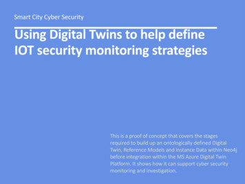
Smart City Cyber SecurityUsing Digital Twins to help defineIOT security monitoring strategiesThis is a proof of concept that covers the stagesrequired to build up an ontologically defined DigitalTwin, Reference Models and Instance Data within Neo4jbefore integration within the MS Azure Digital TwinPlatform. It shows how it can support cyber securitymonitoring and investigation.
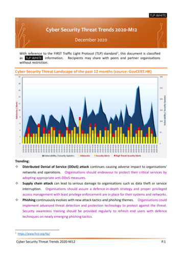
Smart City Cyber SecurityScenarioA near future scenariodescribing themonitoring of theinteraction betweenconnected vehicles suchas Car, eScooters andeBikes and City StreetInfrastructure forsecurity events andcyber attacks.The Theme for thisscenario comes from aresearch project andpresentation.DataEvent and securityevent data is derivedfrom the differentassets directly or fromcloud based CityInfrastructuremanagement systemsand vehicle Backendsystems.SolutionUsing data models,threat models, digitaltwins and event dataderived from assettransactions,interactions and normaloperations.The scenario also usethe AWS IOT ThingsGraph Data Model(TDM) domainconstructs to examinehow data is used tosupport investigationand monitoring.
AWS IOT Things Graph Data Model (TDM) Security Use CasesAWS IOT Things GraphData Model (TDM)domain constructsAWS DescripAonSecurity Control and Monitoring Use CaseStateThe State construct is a set of properties that represent the inner state of a device at a point in time.Determine the normal or abnormal state of operationsMappingThe Mapping construct bridges differences across multiple representations of the same concept. It converts semantically equivalent data from onerepresentation to another. A Mapping creates a single semantic view of data that originates from multiple sources.Version control of configurationEventThe Event construct describes a notification from a device that some action has been taken on it including:- The event name- A unique identifier of the source device of the event- A payload containing information that supports handling of the eventMonitor Events in relation to the result of device actionsActionThe Action construct is an abstract representation of a device performing an instance of its capability. An Action takes properties as its parameters andreturns properties as its output.Monitor Action outputs in relation to an expected outcomeCapabilityThe Capability construct describes a piece of functionality that is implemented by an IoT device. A Capability can extend one or more pre-existingCapabilities. It's a package containing a State and a set of Actions and Events. A Capability definition consists of the following:- A unique identifier- At most, one State- A set of Actions- A set of EventsDefine the properties required to fulfil the Capability as per the expectedActions. Monitor Capability over a time period to determine normal orabnormal patternsDevice ModelThe DeviceModel construct describes an abstraction of an IoT device or a stateful service. A DeviceModel must implement one Capability. It representsa conceptual device and isn't tied to any specific manufacturer.A DeviceModel consists of the following:- A TDM URN that identifies the device model- A TDM URN that identifies the device model's CapabilityThe parent class or master digital twin of the concept. Incorporates theCapabilities and subsequent requirements. This should construct thegeneralised monitoring requirements.DeviceThe Device construct describes a specific IoT device that implements the Capability of a DeviceModel. This is not a concrete device, but an abstractdefinition of a device. After a device is defined in TDM, concrete devices can be mapped to the device definition. A Device definition includes thefollowing:- An implementation of the parent device model's State- An implementation of the parent device model's Actions and Events in the context of a specific communication protocol, such as MQTT or ModbusA sub-class or variant of the Device Model forming a digital twin of thespecification and configuration of the Device for the purpose of associationwith the Asset Management of the physical device.ServiceThe Service construct describes either an AWS Lambda or a RESTful web service that can be called from a Workflow. Conceptually a Service is analogousto a Device, because it can be called inside a workflow step. The structure of a Service is also similar to that of a Device. The primary difference is thatthe Action of a Service is a call to the web service or an invocation of a Lambda function. The Service structure contains the input and outputparameters of the web service or Lambda call.A Service associated with working with the IOT Device may exist as an EndPoint (Tablet or Mobile) App or Cloud application. Requires a digital twin ofthe service / architecture within its service boundaries and its servicemodel. Requires a complimentary monitoring strategy.WorkflowThe Workflow construct (also called flow) describes an automated process that consists of multiple devices and stateful services. Workflow takes a setof parameters and consists of an array of steps that are connected to events. Input events can trigger a step, and a step can generate an output event.Each step can represent a Lambda function, a device action, or a web application method.Monitoring of triggers and actionsSystemThe System construct describes a collection of devices, services, and workflows that interact with each other in an IoT system. For example, a securitysystem can consist of entry sensors, cameras, light bulbs, and a door monitoring workflow. A System can be composed of other systems to createarbitrarily complex systems of systems.Considered as part of situation awareness and broader monitoring of riskand threat intelligence.TriggerThe Trigger construct defines the conditions that start a workflow. Triggers have two components: a condition and a set of one or more actions. Thecondition specifies whether to trigger a new workflow, and an action specifies what the workflow does if the condition is true.Triggers should be classified by the severity of their actions and outcomes socritical triggers are monitored for normal or abnormal behaviours.DeploymentThe Deployment construct associates a physical location with specific devices and the triggers that start the workflows in which they are used.Considered as part of situation awareness and broader monitoring of riskand threat intelligence.
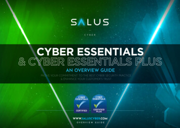
Stage 1Model the Twin EnvironmentThe first stage is to model the domain andThings or Devices under investigation. Thisexample is the interaction between Vehiclesand City street infrastructure such as TrafficLights, Pedestrian Crossings, Lamp Posts andthe City Traffic Management system.
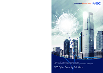
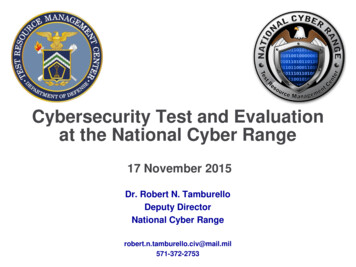
Stage 2Using an ontology development tool, suchas Protege, build up models of the Thingsor entities in the domain model. In thisexample, the image shows the design of aVehicle Function Digital Twin as a subclassof Vehicle. Other subclasses of the classVehicle include Style, Infotainment Systemand Model.The Vehicle Function Digital Twin is acollection of functions that can be subjectto fail if it is impacted by misinformationfrom other infrastructure services such asParking systems or Traffic Lights.
Stage 3Continue the development of ontologicalmodels for other Things in the domainsuch as Traffic Lights. Extend thisdevelopment with the definition andclassification of the security controls,events and monitoring patternrequirements.Each class in the ontology is supported bythe definition of Class Properties, Domainsand Ranges. This forms a semantic triplewhere the Domain Class or Subject has aPredicate or Property relationship with theObject or Range Class. This helps to enrichthe data by making it more explicit andthrough further verification by theextended relationships.
Stage 4Involves the creation of CSV data torepresent the data generated by assetsin the form of TDM State, Event andAction data as well as reference sourcesto form the Instance data set. This isimported into a Graph Database such asNeo4j.The OWL ontology is then imported intoNeo4j through the use of theNeosemantics plugin.Using Neo4j Bloom allows the Instancedata to be viewed as Nodes andRelationships and extended throughassociation or inferences to ReferenceClass models and Digital Twin Classmodels.
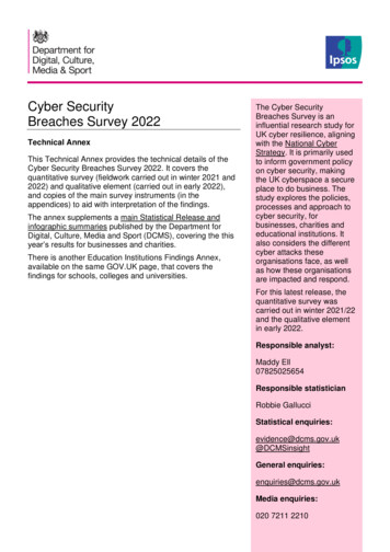
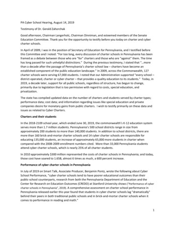
Stage 5Once all the data is uploaded and processed inNeo4j the data patterns and relationships canthen be explored. In this example, the largercircles represent Reference and Digital Twinclasses and the smaller ones the instance data.Here we have data showing that two Vehicles atdifferent locations have recorded a Ransomwaresecurity event.A search query in Neo4j identifies the Nodes andRelationships and the association with theReference Class - Manipulation of Information.
Stage 6The investigation of theevent and data begins byselecting and expandingthe Reference Class Manipulation ofInformation. This extendsthe Node to Domain andSubclass (SCO) references.
Stage 7The Manipulation ofInformation Node is aSubclass of Security Eventand is the Subject of twoPredicates - Is a CityMobility Risk and Is aBusiness Risk. The Rangesor Object Classes wouldrefer to different kinds ofMobility Assets such asVehicles, eBikes orAutonomous Vehicles.Investigation could inferthat this event may impacton other Assets withsimilar properties orvulnerabilities or couldhave occurred elsewhereat other City locations.
Stage 8By extending the VehicleNode the vehicle classrelationship extends to theVehicle Model and Vehicleparent class. Thisreference model providesfurther subclass andpredicate information anda Vehicle Digital Twinmodel of vehicle functions.
Stage 9The Vehicle Digital Twinmodel breaks down intovehicle functions such asAcceleration, ObjectDetection and Navigation. Adomain predicate - Has FailedService - links to knownvulnerability or service historyand a range predicate - HasPolicy - that refers to Vehiclepolicy controls such asSecurity that would detailrules or thresholds.
Stage 10By extending the Vehiclelocation or Street Node toshow that a Traffic Light wasin proximity, therelationship to the TrafficLight Digital Twin mayindicate if there were theDevice Capability (TDM) tocommunicate with theVehicle and if this could bethe possible source of themalware.
Stage 11The Traffic Light Digital Twinhas multiple Subclasses, thatshow Device Capabilities(TDM), that would breakdownfurther into specific classtypes showing features andproperties of the Device(TDM) that couldcommunicate with Vehiclefunctions.
Stage 12A final extension relates the security event to a Mitre Att&ck pattern class tohelp with evidence of known attack methods and vectors. Each extension ofthe original Nodes was able to provide either reference knowledge oradditional support for an investigation through the examination of atechnology Device Digital Twin and its parts and functions. This finalrelationship offers threat hunting research scenarios.
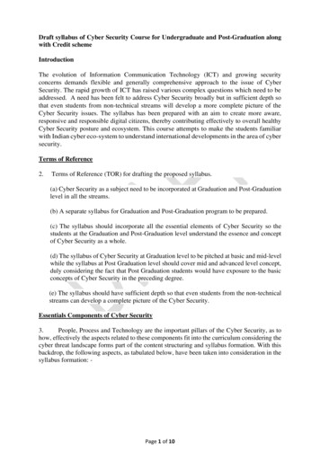
1Proof of Concept1) Building data models and Digital TwinProtege provides the platform to design and developontological reference models and Digital Twins.2) Scenario planning with the data and DigitalTwinsNeo4j provides a platform to upload and analysemultiple instance data sets and with the use of theNeosemantics plugin provides: import of RDF import OWL ontologies model mapping Graph model scenarios basic inferencing233) Building the Digital TwinsUsing MS Visual Code DTDL, MS DT Explorer andthe MS Azure Digital Twin platform to define and buildthe Digital Twins designed in step 1 and 24) Integrate with MS Azure IOT Hub and MSSentinelMonitor physical device state, events and thresholdsthrough the MS Sentinel security platform[ Steps 3 and 4 are not yet covered in this POC]4
Smart City Cyber SecurityFor more information please urity.net/smart-city-cyber-security-framework/
Using an ontology development tool, such as Protege, build up models of the Things or entities in the domain model. In this example, the image shows the design of a Vehicle Function Digital Twin as a subclass of Vehicle. Other subclasses of the class Vehicle include Style, Infotainment System and Model. The Vehicle Function Digital Twin is a