Transcription
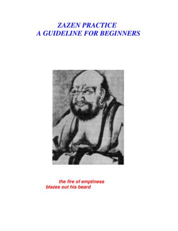
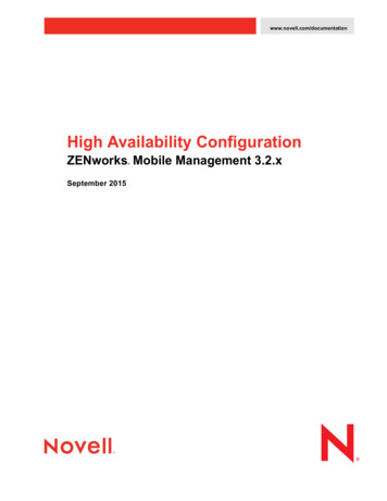
The Zen Variations - Part 2The Penultimate Zen’s Current Sourceby Nelson Pass, (c) 2002 Pass LaboratoriesIntroWelcome back to the Zen Amp Variations. This is part 2 of many partsin which we explore some of the ways to make a very simple audioamplifier. In this and parts 3 and 4 we will embellish upon the originalZen amplifier circuit, improving the performance and creating thePenultimate Zen Amp.You may recall that the Zen Amp is a single MOSFET transistoroperated in what is known as Common Source mode in which the inputsignal is fed to the Gate pin, the Source pin is grounded, and we takethe output signal off the Drain. In order to get this arrangement to work,we have to provide this transistor with a current source, which is justwhat its name implies. It is a source of current which provides the powerfor the gain device. In the case of the Zen amp, the current sources actsas a mediator between the positive voltage supply and the gaintransistor, feeding the right amount of current into the circuit to providethe optimum conditions for the device.If you wish to improve your understanding of the lower portion of thecircuit, I refer you to the original project articles, "The Zen Amplifier",Audio Amateur, issues 2/1994 and 3/1994. These can also be found onwww.passdiy.com .This type of current source is known as a constant current source.Ideally, a constant current source will deliver an exact, unwaveringamount of current out of a connection (in this case the Drain of Q2)regardless of what is attached to the connection or what the voltageconditions at that node might be. If you leave this point unattached tosome circuitry, an ideal constant current source will emit a smalllightning bolt which will travel until it connects to something. The ZenAmp constant current source is not so ideal, but perhaps that is just aswell.The way this current source works is fairly simple. P type MOSFET Q2will conduct current when its Gate pin becomes negatively chargedrelative to its Source pin. An easy way to make that happen is to useR11 to pull the Gate voltage toward ground, and with the Source pinThe current source can be made as simple as aresistor (or a light bulb), but it is generallyadvantageous to make it out of something morecomplex, since using a resistor results in about8% efficiency or so, and this being power circuit,wasting this much power gets costly and issocially incorrect. Just ask anyone who has builtthe Son of Zen, and they'll tell you that burning600 watts to get 50 watts output is a bit over theedge.In this article we will recap the operation of theoriginal current source for the Zen, introduce analternative current source, and then pull a trickout of the hat for a new source of current with anegative and occasionally imaginary sourceimpedance.The Original Source of CurrentFigure 1 shows a version of the original Zen Amp.It is not exactly identical to the original circuit; Ihave played around with it to give continuity tothis article's progress, but it is close enough.The actual gain stage portion of the circuit is Q1and the components attached to it on the lowerhalf of the circuit. Q2 and the components in theupper half of the circuit make up the currentsource.Pass D.I.Y Project: The Penultimate Zen’s Current Sourcepage 1
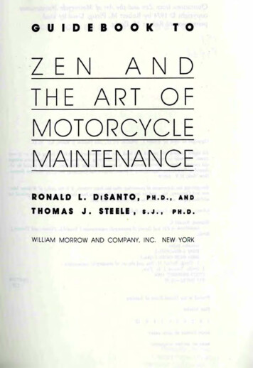
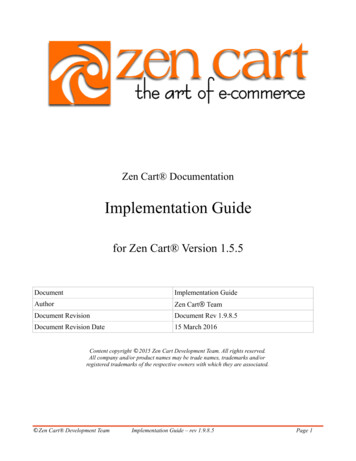
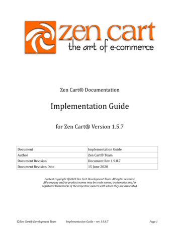
looking at about 40 volts, the MOSFET will beginconducting most enthusiastically.To temper the enthusiasm of this conduction we install theremaining parts of the current source; R1, Q3, R6, C3,and R7. When current begins flowing through theMOSFET, voltage is developed across .33 ohm resistorR1 which will equal .33 volts for each amp of current flow.Q3, a PNP transistor, is set up so that it sees this voltageacross R1. Bipolar transistors have a characteristicwhere they will begin to conduct when their Base toEmitter voltage approaches .66 volts or so, and when thevoltage across R1 gets to about .66 volts, Q3 begins toconduct.By comparison, MOSFETS begin conducting between 2and 5 volts, and are quite variable between types andparts which is why we use a Bipolar device here. But Idigress When Q3 begins to conduct, it limits the Gate voltage ofQ2, and this forms a little feedback mechanism whichlimits the voltage across R1 at about .66 volts. R6, R7,and C3 are there to help make this arrangement stableand reliable, and we could possibly omit these, but wewon't.If the voltage across R1 is a stable and constant .66 volts,then the current through R1 is a stable and constant 2amps, and that means the current through Q2 is a stableand constant 2 amps, and so we have a 2 amp stable andconstant current source. For Drain voltages reasonablywithin the values of the power supply provided, thecurrent will be fairly constant and good enough for thisamplifier.An Alternative ApproachThere is more than one way to skin a current source, andFigure 2 shows an alternative circuit that performs the same function butwith an N channel MOSFET instead of a P channel type. In this circuit,the corresponding parts retain the same reference numbers as Figure 1,with Q2 becoming an N channel part, Q3 becoming an NPN part, andR11 changing value from 10 K ohms to 1.5 K ohms.into a current variable current source as seen in the Pass Labs Alephamplifiers.The function of this circuit is identical to Figure 1 except that it has beenturned upside down. The Gate of Q2 now has to go positive relative tothe Source pin to achieve conduction, and so on. To keep the currentthrough R11 fairly constant as it was with the previous version we haveadded R12 and C5 which "bootstrap" the AC voltage at the junction ofR11 and R12 so that the AC voltage variation seen across R11 is low.Before we do that, let's make note of the performance of the circuit ofFigure 2. Figure 3 shows the harmonic distortion curve versus outputpower into an 8 ohm load, and we see that this rises smoothly fromabout .1% at .1 watts, to about 2% at 10 watts. This is mostly secondorder harmonic distortion until you get above 10 watts, and by about 18watts rms you are clipping the output with peaks at 36 watts. This ismore power than we got out of previous editions of the Zen Amp byvirtue of greater power supply voltage at 40 volts. Into 4 ohms, theamplifier clips at about 9 watts rms.The performance of this circuit is virtually identical to that of Figure 1,and is documented in Figures 3 through 5. One advantage to the circuitof Figure 2 is that it uses the same device as the gain transistor, bothbeing the cheaper and more easily obtained N channel types. The morecrucial advantage to this innovation is that it can be further developedFigure 4 shows distortion vs frequency into the same 8 ohms at 1 wattlevels, and we see an increase at high frequencies with a knee in thecurve at about 6 KHz. The increase at high frequencies is due largelyto nonlinearities in the input capacitance of power MOSFETs and is anunwelcome feature that we have to live with in this device. We minimizePass D.I.Y Project: The Penultimate Zen’s Current Sourcepage 2
The Aleph Current Source: the Altered AlternativeIn 1991 I authored U.S. patent # 5,710,522 which detailed the operationof an active current source which was constant for DC characteristicsbut variable at AC frequencies and which could track an arbitrarypercentage of output current to a load, relieving the active single-endedClass A gain device of some of the work. As a practical matter for audio,the best figure for that percentage is about 50%, and this allows for pureClass A operation to twice the current, boosting efficiency to an ideallimit of 50% over the 25% expected from a constant current source.Instead of the infinite impedance represented by an ideal constantcurrent source, this new variation has a negative impedance equal totwice the load impedance. If the load is 8 ohms, the current source willhave a -16 ohm impedance, and the active portion of the amplifier willthink it is driving 16 ohms. The reactive portion of the loudspeaker issimilarly mirrored in the this manner so that it accurately creates anegative ghost of the load. Think of Sigourney Weaver with themechanized loader in Aliens.This circuit was implemented in the Pass Labs Aleph series of amplifiersand has become known as the Aleph current source. It is fairly painlessto modify the current source of Figure 2 into this circuit, and the result isportrayed in Figure 6.New components are introduced: R13 thru 15 and C6. R13 and 14 aretwo 3 watt .47 ohm metal film resistors paralleled to form a 6 watt .235ohm resistor. They see the output current to the load, and sensingvoltage appears across them which is proportional to this output current.R15 and C6 communicate this to the feedback junction at the Base ofcontrolling transistor Q3, and the current through Q2 varies to supportthis output current.The percentage of current contributed by Q2 is a function of the valuesof R13, 14, and 15 along with the other values of the current source, andin this circuit are set for best sounding performance, which is close to50%. As a practical matter, we would adjust R15 to vary this value.As with the other Zen projects, there is considerably leeway in theselection of values, and if you find that you wish to vary the values of R1,13, and 14 for example, you will end up adjusting the value of R15 to getback to the 50% figure. Or maybe not; perhaps some other percentagewill sound better to you.this effect by minimizing the impedance of our feedback loop in theamplifier, Resistors R2 and R3. Unfortunately this also minimizes theinput impedance of the amplifier, making it more difficult to drive. We willbe addressing this problem in Part 4 and other parts of this series.Figure 5 shows the frequency response curve of this amplifier, which isseen to be absolutely flat to 10 Hz and down 2 dB at 100 Khz. Thedamping factor of this amplifier is about 8 against 8 ohms, giving it a 1ohm output impedance, typical of tube performance.Pass D.I.Y Project: The Penultimate Zen’s Current SourceIn any case, to achieve this 50%, you would have to adjust R15 so thatthe AC current through R1 is one half the current going through theparallel R13 and 14. In the case of the values shown, that means thatwhen the amplifier is driving a load, the AC voltage across R1 is 70% ofthe voltage across the combination of R13 and 14. You can use an ACvoltmeter at 60 Hz to check this figure if you need to confirm properoperation of the circuit. Decreasing R15 increases the percentage, andvice versa. If you want a switchable variable/constant current source,install a switch to break the R15 circuit.Figure 7 shows a comparison of the distortion vs power of the circuits ofFigure 2 and Figure 6. It's a pretty straightforward result: the distortiondrops by a factor of about 10.page 3
Figure 8 shows the same comparison at 4 ohms. Again, a factor of 10reduction until about 9 watts, where the older circuit clips and the newercircuit goes on to hit 1% distortion at 35 watts.The damping factor of the newer circuit is approximately 40, for anoutput impedance of about .2 ohms, five times better than the oldercircuit.Figure 9 shows the distortion vs frequency for the two circuits. Alas, thedramatic improvement doesn't hold up as well at high frequencies, whichwe will be addressing in part 4.Pass D.I.Y Project: The Penultimate Zen’s Current Sourcepage 4
OutroWell there you have it, the first major improvement of the original ZenAmp in 8 years. It sounds about as good as it looks. The bottom end isa lot tighter, there is greater clarity in the mid-band, and there is morepower and dynamic range. You can operate this one balanced for about70 watts into 8 ohms with even lower distortion. If you have already builtthe Zen, you can easily adapt it to the newer circuit, and it will performwell with the original 32 volt supply (although with somewhat lesspower).In part 3 we will build an active power supply regulator for the Zen, andin part 4 we will raise the input impedance to 47 K ohms and clean upsome of the high frequency distortion. The result is fairly spectacularwith minimal additional complexity and cost. And finally, the PenultimateZen will get a PC board and a partial kit will become commerciallyavailable thru www.passdiy.com .The Aleph current source is still covered by U.S. patent # 5,710,522, butas a matter of policy we do not concern ourselves with DIY efforts. Allothers can send checks to:nelson@passlabs.comPass D.I.Y Project: The Penultimate Zen’s Current Sourcepage 5
Welcome back to the Zen Amp Variations. This is part 2 of many parts in which we explore some of the ways to make a very simple audio amplifier. In this and parts 3 and 4 we will embellish upon the original Zen amplifier circuit, improving the performance and creating the Penultimate Zen Amp. You may recall