Transcription
HeatMasterInstallation, Operating andServicing InstructionsHM 71HM 101excellence in hot water66401100
INDEXINTRODUCTIONINTRODUCTION1INTENDED USERS OF THESE INSTRUCTIONSIntended users of these instructionsSymbolsApplicable standardsWarnings1111These instructions are intended for- specifying engineers- installing engineers- end-users- servicing engineersDESCRIPTION2Operating principleConstruction features22TECHNICAL SPECIFICATION4Essential instruction for operating the systemcorrectly.DimensionsGeneral featuresMaximum operating conditionsDomestic hot water performancesHeatMaster control settings44555Essential instruction for personal safety orenvironmental protection.INSTALLATION6Danger of electrocution.SYMBOLSBoiler roomChimney connectionsHot water connectionsHeating connectionElectrical connectionWiring diagram66891011COMMISSIONING12Filling the hot water and heating circuits12BURNER FEATURES12ACV BG 2000-M moduling premix gas burners12MAINTENANCE14Service IntervalsServicing the boilerServicing the safety devicesServicing the burnerDraining the boiler1414141414The following symbols are used in these instructions:Risk of scalding.APPLICABLE STANDARDSThe products have received the “CE” certificate in accordance withthe standards prevailing in different countries (European Directives92/42/EEC, “efficiency”, 90/396/EEC “gas appliances”). Theseproducts have also received the Belgian “HR ” (gas boilers) marks.WARNINGSUSER GUIDE15Using the boilerControl Settings1516SERVICE RECORD18These instructions are an integral part of the equipment to whichthey refer and must be supplied to the user.The product must be installed and serviced by qualified engineers,in compliance with the prevailing standards.ACV accepts no liability for any damage resulting from incorrectinstallation or from the use of components or fittings not specified byACV.Failure to observe instructions regarding tests andtest procedures can result in personal injury orpollution risks.Note:ACV reserves the right to modify the technical specifications andcomponents of its products without prior notice.1
DESCRIPTIONOPERATING PRINCIPLECONSTRUCTION FEATURESThe HeatMaster is a high performance, direct fired hot water storageheater, which has indirect heat transfer due to its Tank-in-Tankconstruction.Outer bodyAt the heart of the HeatMaster is a stainless steel cylinder throughwhich the flue tubes pass. This is surrounded by a mild steel shellcontaining the primary water (neutral fluid). The outer shell extendsdown to the combustion chamber and even around the flue tubes.The area of the heat transfer surface is therefore much greater thanthat of standard direct fired water heaters.TANK-IN-TANK heat exchangerA circulating pump fitted to the primary circuit moves the wateraround the tank, heating it faster and maintaining an eventemperature across the primary jacket.Combustion gas circuitThe burner, either gas or oil, fires onto the primary water whichindirectly heats the stainless steel cylinder containing the DHW. Aswith all Tank-in-Tanks, this is corrugated over its full height andsuspended in the HeatMaster by its hot and cold water connections.The cylinder expands and contracts during use and this, togetherwith the fact that cold water does not come into contact with theintense heat of the burner flame, means that limescale buildup isprevented.This scale resistant feature, along with the corrosion resistance ofstainless steel, eliminates the need for sacrifical anodes.The HeatMaster has one very major advantage over other directfired water heaters - because it heats the DHW with a primarycircuit, this primary water can be used to provide central heating aswell.By connecting two, three, four or more HeatMasters together in amodule, most hot water and heating demands can be met.Indeed, when used in conjunction with HR and Jumbo hot waterstorage tanks the Heatmaster can supply even the largest hot waterrequirement.Standard equipmentThe HeatMaster 71/101 has the following items as standard :- On/off switch- Summer/Winter switch- MCBA controller, incorporating electronic control and high limit thermostats burner modulation- primary circulating shunt pump- primary expansion vessels- primary safety valve- pressure and temperature gauge- drain valve- body completely insulated in rigid polyurethane foam2The outer body containing the primary fluid is made of carbon steel(STW 22).The ring-shaped inner tank with its large heating surface for producingdomestic hot water is built of Chrome/Nickel 18/10 stainless steel. Itis corrugated over its full height by an exclusive production processand entirely argon arc welded by the TIG (Tungsten Inert Gas)method.The combustion gas circuit is paint protected and comprises: Flue pipesHeatMaster 71/101 models contain 8 steel flue pipes with aninternal diameter of 64 mm. Each pipe is fitted with aturbulator of stainless steel designed to improve heatexchange and to reduce flue gas temperature. Combustion chamberThe combustion chamber on HeatMaster models is entirelywater cooled.InsulationThe boiler body is fully insulated by rigid polyurethane foam with ahigh thermal insulation coefficient, sprayed on without the use ofCFCs.CasingThe boiler is covered by a steel casing which has been scoured andphosphated before being stove enamelled at 220 C.Burner71 and 101 models are always delivered with ACV BG 2000-M 71and 101 air/gas premix burners.
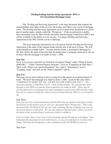
DESCRIPTIONTop coverFlue reduction collarAutomatic air ventDomestic cold water inletHeating circuit fillingvalve with removable hoseand non-return valvePrimary expansion vesselCentral heating flow pipeDomestic hot water outletFlue pipes and turbulatorsTank-in-Tank heat exchangerInsulationPrimary shunt pumpBurnerCasing front panelHeating returnPrimary circuitBurner chamber plateCombustion chamberDetector NTC1 and NTC2Low water pressure switchDetector NTC3Primary safety valve3
TECHNICAL SPECIFICATIONDIMENSIONSThe units are delivered fully assembled, tested and packed on a timber base with shockproof edges and protected by heat-shrunk plastic film.On delivery and after unpacking, check the equipment for damage. For transport purposes, refer to the weights and dimensions given below.GFKAHBC/2JCEDA mmB mmC mmD mmE mmF mmG Ø mmH mmJ mmK mmHM 711743163068093768039015012892851720HM 1012093203068093768039015016932852120GENERAL FEATURESHM 71HM 101typeNatural gas / propaneNatural gas / propaneMaximum InputkW20 - 69.925 - 107 / 22 - 110Maximum OutputkW63.096.8%0.50.4FuelMaintenance loss at 60 C of rated valueTotal capacityL239.0330.0Primary circuit capacityL108.0130.0Hot water connectionØ1”1”Heating connectionØ11/2”11/2”Ø mm150150Hot water tank heat exchange surface2m3.143.95Weight emptyKg282335mbar4683Flue connectionPressure drop primary circuit4
TECHNICAL SPECIFICATIONMAXIMUM OPERATING CONDITIONSHEATMASTER CONTROL SETTINGSMaximum service pressure (tank full of water)- Primary circuit: 3 bar- Secondary circuit: 10 barDescriptionThe 71/101 series is fitted with an electronic controller (MCBA)which controls burner operation (ignition, safety and modulation),and provides facilities to adapt the controller to the desired application.Test pressure (tank full of water)- Primary circuit: 4.5 bar- Secondary circuit: 13 barThe MCBA has three levels of settings : manufacturer, installer anduser. There are three temperature detectors located in the primaryand secondary circuits.Operating temperatureMaximum temperature: 90 CIt provides two operating modes.Water quality Chlorures: 150 mg/l (304) 2000 mg/l (Duplex)1. Heating modeTemperature set by the user at between 60 and 90 C. 6 ph 8 Differential “ON”, burner starts.Differential “OFF”, burner stops.PI (Proportionnel Integral) regulator in “heating” mode.The regulator compares the primary temperature with the settingand modulates.DOMESTIC HOT WATER PERFORMANCESThe room thermostat detects the heating demandHM 71HM iverydeliveryatatatatat4045607080 C C C C rydeliverydeliverydeliveryatatatatat4045607080 C C C C ousReheat time to 60 C4045607080 C C C C C2. Hot water mode (with hot water priority)The detector located in the secondary tank detects the hot waterdemand.When a draw-off is detected the controller goes to “hot waterdemand” mode: The primary shunt pump starts.The heating pump switches off.The burner starts and the controller uses the data from theprimary detector to control modulation.User-accessible parameters1.2.3.4.“Hot water” setting adjustable from 20 to 90 C.“Hot water” mode: ON/OFF.“Heating” mode: ON/OFF.“Heating” setting adjustable from 60 to 90 C.Parameters accessible in servicingMain default settings:- Hot water priority active.- Heating demand detection by room thermostat.- A single heating circuit.An access code is required for “service” access.For more technical information, contact your ACV dealer.5
INSTALLATIONBOILER ROOMCHIMNEY CONNECTIONSImportant Keep vents free at all times. Do not store inflammable products in the boiler room. Do not store corrosive products near the boiler, such as paints,solvents, chlorine, salt, soap and other cleaning products. If you smell gas, do not switch on the light or light a flame. Turn offthe mains gas tap at the meter and inform the appropriateservices immediately.IMPORTANTBoilers must be installed by an approved heatingengineer, in accordance with the prevailing localstandards and regulations.Flue size should not be less then the outlet size of theboiler.AccessThe boiler room must be large enough to allow good access to theboiler. The following minimum distances are required around the boiler:Chimney connection type: B23-frontsidebehindabove500100150700mmmmmmmmThe boiler is connected to the chimney by a metal pipe rising at anangle from the boiler to the chimney.A flue disconnection piece is required.This must be easy to remove to give access to the flue pipes whenservicing the boiler.VentilationThe table below gives an example conforming to the Belgian standards.VentilationMin. fresh air requirementBottom ventTop ventm /hdm2dm23711011262.42.01943.202.0A. Top ventB. Bottom ventC.Draught regulatorD. Inspection openingE. Lined chimney heightF. Chimney diameterFEThe boiler room must be fitted with top and bottom ventsaccording to the prevailing local standards and regulations.Other countries should refer to their own standards.BaseCAThe base on which the boiler rests must be made of non-combustiblematerials.BDChimney / minimum flue diameter71101E 5 m Ø F min.E 10 m Ø F min.E 15 m Ø F min.189159150234178150mmmmmmNote:Regulations vary from country to country thereforethe table above is intended only as a guide.Due to the high efficiency of our boilers, the flue gassesexit at low temperature. Accordingly, there is risk thatthe flue gasses could condense, which could damagethe chimney. In order to avoid this risk, it is stronglyrecommended that the chimney be lined.6
INSTALLATIONBalanced flue boiler connection type: CC33120C13150 min.C13: concentric horizontal connectionC33: concentric vetical connectionC53: parallel chimney connectionC63: concentric vertical connection without terminal (only inGermany and Luxembourg).C532 m min. Maximum length concentric : 6 metresMaximum length parallel : 12 metresNote: a 90 degree bend 1 metre equivalent lengthA condensation drain outlet must be fitted close to the boiler to prevent condensation products fromthe chimney running into the boiler.To avoid condensation water running out of the terminal, all horizontal flue runs must fall backtowards the boiler.7
INSTALLATIONHOT WATER CONNECTIONSExample of parallel connectionRecommended for applications with a high continuous flow.Pressure reducing valveIf the mains water pressure is greater than 6 bar, a pressure reducingvalve must be fitted.Expansion relief valveThe tank expansion relief valve must be ACV approved andcalibrated to a maximum of 7 bar. The valve discharge must beconnected to the drain.Hot water expansion vesselA hot water expansion vessel must be installed.Hot water circulationIf the tank is situated a long way from the point of use, theninstalling a recirculation loop can provide a faster supply of hot waterto the outlets.Temperature and pressure relief valveIf using the HeatMaster as an unvented hot water unit, in somecountries, a temperature and pressure relief valve must befitted - consult your ACV stockist for assistance.Example of hot water connection with thermostatic mixer1. Stop cock2. Non-return valve3. Pressure reducing valve4. Expansion relief valve5. Hot water expansion vessel6. Hot water secondary pump (if fitted)7. Thermostatic mixing valve8. Drawoff tap9. Drain cock10.Stop cock for cleaning11.Primary circuit filling valves12.Temperature relief valve (UK only)2123Example of series connectionPreferable for high temperature applications with up to three units.68741012511Example of heating storage connectionRecommended for applications requiring a high peak flow.9DANGER!As a safety measure against scalding, westrongly recommend installing a thermostaticmixing valve.8
INSTALLATIONHEATING CONNECTIONThe HeatMaster has two connections at the rear that can be used toconnect a central heating circuit. Connecting a heating system mayreduce the domestic hot water performance.WARNINGThe maximum pump motor load for the MCBA is 250Watt. If a larger pump is required, install a relaybetween the pump and the MCBA.ExpansionHeatMaster 71/101 models are fitted with two 10 litre expansionvessels, which are sized for hot water operation only. If a heating system is connected to the primary circuit, calculate the expansion capacity necessary for the total volume of the heating system (Refer to thetechnical instructions from a relevant manufacturer of expansion vessels.)Example of a single circuit connection1. 3-way valve.2. Heating pump.3. Non-return valve.4. Isolating valve.5. Safety valve set to 3 bar with pressure gauge.6. Expansion vessel.7. Drain cock.8. Primary circuit filling valve.9. Controller.8912345647WARNINGThe pimary safety valve is supplied with a plastic tubeconnected to the discharge outlet - this is for testpurposes only and should be removed. The safetyvalve should be connected to a drain using a metallicpipe eg. copper.9
INSTALLATIONAlarm - moduleELECTRICAL CONNECTION Connect the flat ribbon cable from the alarm-module “X7” to MCBAconnector “X8”.Power supplyThe boiler operates with a 230 V - 50 Hz single phase supply.A double pole isolator with a 6 amp fuse or a 6 amp MCB must befitted outside the boiler to allow power to be shut off during servicingand before any repairs are carried out on the boiler.The volt free relays mounted on the alarm module will now beactived as described below:Conformity2 - External gas valve / burner - run indication:This contact closes if a heat request is present and the fan is running.1 - Alarm:This contact closes if the MCBA is in lock out.Boiler installation must comply with the prevailing local standardsand legislation.3 - Domestic Hot Water pump:This contact closes if a Domestic Hot water heat request is present.SafetyThe stainless steel tank must be earthed separately. Technical data:- Ambient temperature:- Contact ratings:The power to the boiler must be switched off beforeany work is carried out.0 60 CIRMS 1A230 V ( 10% / 15%) 50 HzIf inductive loads are connected, take precautions overthese loads against peak voltages (e.g. RC-network).1Internal MCBA connections2Alarm - moduleX1: Connection MCBA 230 Volt3X2: 24 Volt connectorX3: NTC - connectorX4: NTC 5 - analogue in connectorX5: Communication / NTC 4 - connectorConnectionfor transformerX1X2X3X4X5MCBAX8:Ribbon cableconnection foralarm module(option)10X7:Displayconnection
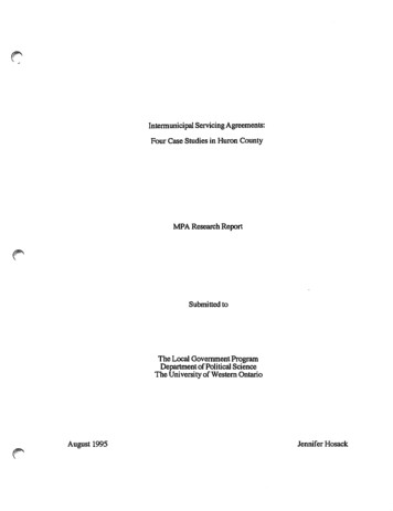
INSTALLATIONHeatMaster 71/101 andburner wiring diagram legend1617V1 V2C 1BBrRBBG 2000-M/101Br15V1 V2BBBrY/GrL1 NG7-pin burner plug connector4-pin burner plug connectorOn/off switchPower and pump connectionCentral heating pumpHeatMaster shunt pumpRoom thermostatLow water pressure switchPrimary temperature detector NTC 1Primary temperature detector NTC 2Hot water temperature detector NTC 3Summer/winter switchFan power supply 230 voltsFan PWMGas valve rectifierGas valve rectifier (HM 101)Gas pressure switch (optional)Bk141 2 3 4 GreenYellow / GreenL1RBkBGBBrY/GrB BBrN T1 T2 S3 B4F1BrOrB5 T6 T7 T8FB5 T6 T7 T8MBG 2000-M 71/1012L1N T1 T2 S3 B4MHEATMASTER 71/101BBrO-WBkYBrBBrY/GrO-WBkBBBOrBkBX41 2 3RGRGrX31 2 3 4 5WBrO-WOrO-WX21 2 3 4 5 6 7 8 9 10 11 12Y/GrYBkYBrBBkBrBkX11 2 3 4 5 6YBrACV / MCBAB3BkL1N T1 T2 S3 B4FL1N T1 T2 S3 1 2 3 4 5 6 7 8 9 10 11 12 13 14 15 16 17 18 19 .14.15.16.17.B.Br.Bk.Or.G.R.O-W.W.Y.Gr.Y/Gr.56230V 50 Hz11
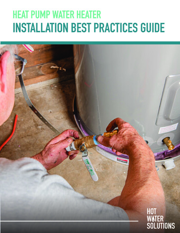
COMMISSIONINGBURNER FEATURESFILLING THE HOT WATER AND HEATING CIRCUITSACV BG 2000-M MODULATINGPREMIX GAS BURNERSDescription of operation:IMPORTANTThe hot water tank must be pressurised before theheating circuit is filled.1. Close the primary circuit filling valves (11).2. Open the stop valve (1) and the drawoff tap (8).When water flows out of the tap, the hot water tank is full andthe drawoff tap (8) should be closed.3. Fill the primary (heating) circuit by opening the valves (11) andpressurising to 1 bar.21236874The BG 2000-M modulating burner continually adjusts output todemand, improving operating efficiency.The burner tube is coated with metal fibre (NIT) which, in addition toits remarkable heat exchange capabilities, gives greater durability.The main components are a venturi and one (model 71) or two(model 101) gas valves, technology specially developed byHoneywell for low Nox premix air/gas burners with automatic ignitionand ionisation flame detection.The pressure at the gas valve outlet is equal to the air pressure inthe neck of the venturi, less the offset. The fan sucks combustion airthrough the venturi, into which the gas inlet emerges.As it passes through, the air produces a pressure differential in theconstriction of the venturi and sucks the gas into the venturi outlet.A perfect mix of air and gas then passes through the fan to theburner tube.1012511This design ensures very quiet and safe operation: If there is an air blockage, the pressure differential in the venturifalls, the gas flow diminshes, the flame goes out and the gasvalve closes: the burner is in safety shutdown mode. If there is a blockage in the chimney outlet, the air flow diminishes,and the same reactions as those described above cause theburner to shut down in safety mode. The BG 2000-M burner fitted to the HeatMaster 71 and 101 isregulated by a MCBA controller (Honeywell) which controls burneroperating safety as well as temperature modulation.9BG 2000-M burners are preset at the factoryfor natural gas.4. Open the automatic air vent located on top of the boiler.IMPORTANT - the screw cap must be left loose to allow futureautomatic venting to take place.Conversion to propane:5. After venting the air from the system, bring the pressure up tothe static head plus 0.5 bar: 1.5 bar 10m and 2 bar 15 m.6. Check that the electrical connection and boiler room ventilationconform to the relevant standards.7. Switch the on/off switch to the ON position.Not applicable for Belgium.Conversion kit included with burner comprising:- Cap(s)- Nameplate(s)- Sticker with settings.- Mounting instructions.Air-gas mixture control system8. Set the temperature settings (see pages 15-16).9. Check the gas supply pressure (see page 13).10. When the burner operates, check the chimney connection forleaks.11. After 5 minutes of operation, turn the boiler off and vent the heatingcircuit system again maintaining the water pressure at 1 bar.12. Then restart the unit and check the combustion (see page 13).Burner troubleshootingSee page 15-17Spare partsRefer to the specific document available from ACV or your distributor.12VenturiFanAir - gasmixtureAirOffset regulationscrewGasGas flowregulating screw
BURNER FEATURES71/101 Gas burner featuresTypeHM 71HM 10122.0 - 69.918.4 - 63.025.0 - 107 / 22.0 - 110 (*)23.0 - 96.3 / 20.2 - 99.0 (*)92.09.092.19.5m3/h2.12 - 7.402.64 - 11.32m3/h2.46 - 8.603.80 - 13.17m3/h0.82 - 2.860.94 - 4.50mbar C0.61721.41659.2 - 32.111.5 - 49.2InputOutputKwKwCombustion efficiency - natural gasNatural gas CO2%%Gas G20 - 20 mbar - I 2E(S)B - I 2 Er - I 2HFlowGas G25 - 20/25 mbar - I 2L - I 2ELLFlowGas G31 - 37/50 mbar - I 3PFlowPressure drop combustion chamberFlue gas temperature (net)Mass flow rate of combustion products (grammes per second)(*) propaneGas categoryBEI 2ErXI 2E(S)BXFRI 2HI 3PXATDKESUKITPTIESEXXXXXXXXXXXXXI 2LNLLUDEXXXI 2ELLBG 2000-M/71BG 2000-M/101Burner tubeBurner tubeIgnition electrodeAir collectorIgnition electrodeAir collectorFanGas valveGas inletFanGas valveGas inletGas collector13
MAINTENANCESERVICE INTERVALSDRAINING THE BOILERACV recommends that boilers should be serviced at least once a year.The burner must be serviced and tested by a competent engineer.If a boiler is subject to heavy use, it may require servicing more thanonce a year - consult ACV for advice.Water flowing out of the drain cock may beextremely hot and could cause severe scalding.Keep people away from discharges of hotwater.SERVICING THE BOILER1. Turn OFF the on/off switch on the boiler control panel and isolateexternal electrical supply.2. Turn off the gas supply to the boiler.3. Remove the flue to gain access to the top of the boiler.4. Remove the casing top panel and lift off the flue reduction collarby undoing the fastening bolts.5. Remove the turbulators from the flue pipes for cleaning.6. Unscrew the burner chamber plate and remove the burner.7. Brush the flue pipes .8. Clean the burner chamber and the burner.9. Re-assemble turbulators, flue reduction collar and flue, checkingthat the gasket on the flue reduction collar is in good condition.Replace gasket if necessary.Draining the heating circuit1. Turn OFF the on/off switch on the boiler control panel, isolateexternal electrical supply, and turn off the gas supply to the boiler.2. Close the isolating valves (4).3. Connect a hose to the drain cock (7).4. Open the drain cock to drain the primary circuit.891324Chimney flueCasing top panel5Flue reduction collar647Draining the hot water circuitFlue pipe andturbulatorsBurnerchamber plate1. Turn OFF the on/off switch on the boiler control panel, isolateexternal electrical supply, and turn off the gas supply to the boiler.2. Release the pressure in the heating circuit until the pressuregauge indicates zero bar.3. Close stop cock (1) and turn off tap (8).4. Open valve (9) then valve (10).5. Let the water empty into the drain21Burner chamber23687410125SERVICING THE SAFETY DEVICES11- Check that all thermostats and safety devices are working properly.- Test the safety valves on the central heating and hot water circuits.SERVICING THE BURNER- Check that the insulation and gasket on the burner chamber plateare in good condition - replace if necessary.- Check and clean the burner and electrodes. Replace electrodes ifnecessary (under normal use once a year).- Check that the safety components are working properly.- Check the combustion (CO2, CO and gas pressure) and recordthe values and any remarks in the Service Record on page 18.9For the tank to be emptied, valve (9) must be situatedat ground level.14
USER GUIDEUSING THE BOILERYour system should be serviced at least once a yearby a qualified engineer.If the boiler is subject to heavy use, it may requireservicing more than once a year - consult your serviceengineer for advice.Starting the burner:In normal operation, the burner starts automaticallywhenever the boiler temperature falls below the settemperature.Understanding the control panelSummer/winter switchMCBA controller - displayOn/off switchCombined temperature and pressure gaugeThere are no user parts inside the control panel.Heating system pressureFrom time to time you may need to top up the heatingsystem pressure. This pressure is indicated by the combinedtemperature and pressure gauge on the boiler controlpanel.The minimum pressure when the boiler is cold should be1 bar. The precise operating pressure required depends onthe height of the building, and your installer will haveinformed you of this value at the time of installation (seeCommissioning Section - Filling the hot water and heating circuits).AIf the pressure falls below 1 bar, the boiler water pressureswitch will turn the boiler off until pressure is restored.To re-pressurise, the system needs to be topped up withwater.First, switch the boiler OFF on the on/off switch and isolatethe external electrical supply. Then remove the casing topfront panel by pulling it forward. The filling valves “A” and“B” can now be seen. Open both valves and allow thesystem to fill. When the combined temperature andpressure gauge shows the required pressure, close bothvalves. Replace the casing top front panel. Restore thepower supply and switch the boiler on.BSafety ValvesIf water discharges from any of the safety valves, switch the boileroff and call a service engineer.15
USER GUIDECONTROL SETTINGS0 80The boiler is controlled by the MCBA (microprocessor), with thecontrol panel housed behind a flap on the front of the boiler - seepicture on page 16.Standby ModeStandby Mode is the normal operation display setting.The first digit shows the boiler sequence. This sequence relates tocurrent boiler status. The last two digits show the boiler temperature.SequenceBoiler status0Stand By, no heat request1Pre-purge, post-purge2Ignition3Burning in CH-mode4Burning in DHW-mode5Waiting for opening of Air pressure switch (max. 1 Min.)Changing the MCBA settings: Parameter mode6Burner off because the set-value has been reachedProceed as follows: Press the “MODE” button once; the display will show “PARA”.Press the “STEP” button once; the first digit is “1” and the lasttwo show the setting for the first parameter. To change these last two, press “ ” to increase and “-” to decrease. Save the new setting selected with the “STORE” button. To access the next parameter, press “STEP”. Press the “MODE” button twice to return to standby mode.7Overrun time pump in CH-modeList of accessible parameters:8Overrun time pump in DHW-mode9Burner off because of protection:Waiting for closing of Air pressure switch (max. 2 x 1 Min.)Parameter N DescriptionRange1hot water setting2“Hot water” system statusO OFF; 1 ON20 - 90 C3“Heating” system statusO OFF; 1 ON4Heating setting(automatic restart occurs when the condition has cleared) “b08”: airflowsensor did not close “b18”: T1 95 C60 - 90 C “b19”: T2 95 C “b24”: T2 - T1 10,20 or 40 C after 19 minutes “b25”: dT1/dt Maximum Gradient T1 “b26”: Minimum gas pressure switch not closed “b28”: no fan signal “b29”: fan signal, incorrect fan rotation “b30”: T1 - T2 Max. delta “b33”: NTC3 short circuit “b35”: NTC5 short circuit “b38”: NTC3 open circuit “b40”: NTC5 open circuit “b52”: T5 T5max “b61”: airflowsensor closed “b65”: wait for fanstartAInternal controlGBurner on for holding boiler warmHBurner-high function: Testmode max. RPM in CH-modeLBurner-low function: Testmode min. RPM in CH-modetBurner on for manual fanspeed (servicing)If the burner is turned off because of an extra protection, the displayshows boiler-sequence 9 and the flow-temperature. This alternateswith the error code eg. b26.16Temperature measurement display: Info modeProceed as follows: Press the “MODE” button twice; the display will show “INFO”. Press the “STEP” button once; the first digit is the measurementnumber and the last two its value. Press the “STEP” button to display the next measurement. To return to standby mode, press the “MODE” button once.List of measurements available:Measurement N Description1Temperature T1 - primary2Temperature T2 - primary3Temperature T3 - secondary4-5-6Setting for T17Variation of T1 - C/s8Variation of T2 - C/s9Variation of T3 - C/s
USER GUIDESafety shutdownIf an operating error develops, the system locks and the displayflashes: the first digit shows the sequence the burner was in whenthe error occurred, the last two digits show the error code (see tablebelow); the first digit and the next two flash alternately.To reset the system: Press the “RESET” button on the MCBA display. If an error occurs again, call an approved heating engineer.Table of error codes and corrective actioncodesError descriptionFault repair00No flame detected- check wiring / - change electrode / - change MCBA02No ignition after 5 attempts- check ignition electrode and its positioning03-07Internal error- if the problem persists after 2 resets, change the MCBA11Eprom error- if the problem persists after 2 resets, change the MCBA12Low water pressure or 24V fuse failure- top up the primary circuit (see Using The Boiler - Heating System Pressure).- call engineer to check fuse13-17Internal error- if the problem persists after 2 resets, change the MCBA18Primary temperature 1 110 C- check that sensor NTC1 is propely housed in its pocket19Primary temperature 2 110 C25Primary temperature 1 gradient too high- check that the shunt pump is operating, and if so vent the boiler28No fan signal- if the fan is turning:- if so, change sensor NTC1- check that sensor NTC2 is propely housed in its pocket- if so, change sensor NTC2 check the PWM connection if the problem persists after 2 resets, change the fan if the problem persists after 2 resets, change the MCBA- if the fan is not turning: check the
Combustion gas circuit The combustion gas circuit is paint protected and comprises: Flue pipes HeatMaster 71/101 models contain 8 steel flue pipes with an internal diameter of 64 mm. Each pipe is fitted with a turbulator of stainless steel designed to improve heat exchange and to reduce flue gas temperature. Combustion chamber