Transcription
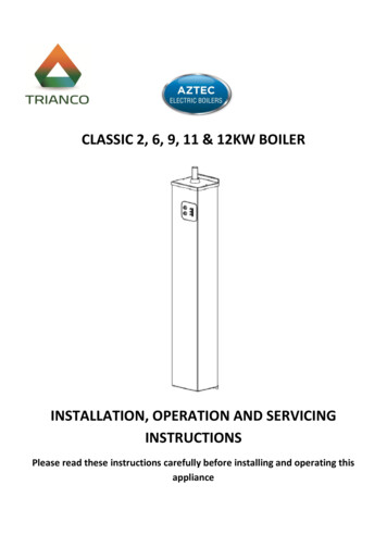
Aztec Classic Electric BoilersCLASSIC 2, 6, 9, 11 & 12KW BOILERINSTALLATION, OPERATION AND SERVICINGINSTRUCTIONSPlease read these instructions carefully before installing and operating thisappliance1
Aztec Classic Electric BoilersCONTENTS1. Health & Safety2. Pre-Installation Notes2.1 Ventilation and Siting2.2 Power Supply and Wiring2.3 System3. After Sales Service Information3.1 How to Report a Fault3.2 Technical Assistance4. Introduction5. Users Instructions6. Simple Fault Finding7. Technical Specification8. Installation Instructions8.1 Regulations8.2 Health & Safety at Work Act8.3 Siting the Boiler8.4 Unpacking the Boiler8.5 Fixing to the Wall8.6 Ventilation Requirements8.7 Water Systems9. Multiple Boiler Installations10. Wiring Instructions11. Servicing Instructions11.1 Parts Replacement11.2 Casing Removal11.3 PCB Assembly Replacement11.4 High Limit Thermostat Replacement11.5 Thermistor Replacement11.6 Element Replacement12. Fault Finding13. Spares 1823-24Important:General Information:To keep your boiler running efficiently DO NOT OBSTRUCT OR COVER any ventilation air inlet on the appliance or the compartment where it isinstalled.To keep the casing clean, switch ‘OFF’ the boiler at the electrical supply and simply wipe with a damp cloth. DO NOT use abrasive cleaning fluids asthis may damage the stove enamel paintwork.ImportantThe electrical supply requirements:The 2kW boilers and 6kW boilers meet the requirements of EN 61000-3.3.The 9kW and 11kW boilers must be installed in premises having a service of 100A per phase.The 12kW boiler must be installed in premises having a system impedance of not more than 0.1939 0.1939Ω.2
Aztec Classic Electric Boilers1. Health & SafetyInformation for the Installer and Service EngineersUnder the Consumer Protection Act 1987 and the Health & Safety atWork Act 1974, it is a requirement to provide information onsubstances hazardous to health (COSHH Regulations 1988).The company takes every reasonable care to ensure that theseproducts are designed and constructed to meet these general safetyrequirements, when properly used and installed.To fulfil this requirement products are comprehensively tested andexamined before despatch.When working on the appliance it is the Users/Engineersresponsibility to ensure that any necessary personal protectiveclothing or equipment is worn appropriate to parts that could beconsidered as being hazardous to health and safety.This appliance may contain some of the items below:INSULATION AND SEALSMineral fibre, insulation.May be harmful if inhaled. May be irritating to the skin, eyes, noseor throat. When handling avoid inhalation and contact with eyes.Use (disposable) gloves, face masks and eye protection.After handling wash hands and other exposed parts. Whendisposing, reduce dust with water spray, ensure parts are securelywrapped.GLUES, SEALANTS & PAINTGlues, sealants and paints are used in the product and present noknown hazards when used in the manner for which they areintended.Notes:a) Electrical safety checks should be carried out by a competentperson.b) It is a requirement of the guarantee and any extended warrantythat an annual service is carried out by a competent person.Installation Engineers SignatureCompany Name (if applicable)Company AddressCompany Tel. No.2. Pre-Installation NotesBefore installation, it is imperative that the following guidelines areheeded to ensure the trouble-free and efficient operation of theboiler.2.1 Ventilation and SitingWhen siting the boiler in a confined space it is essential thatadequate ventilation be provided. This will ensure that air is allowedto circulate freely around the appliance keeping down the ambienttemperatures. Refer to Ventilation Requirements (Page 7) forfurther details.Ensure that the area surrounding the boiler is kept free of itemswhich would impede the good ventilation of the appliance (e.g.towels, linen, etc.).When siting the boiler, take into account the potential requirementfor future servicing. Enough space should be provided at the front ofthe boiler to enable an engineer to adequately service and/orreplace items such as the PCB or heat exchanger. Space should alsobe available for the removal of the front casing panel. Please refer tositing information (Page 6) for clearance dimensions.2.2 Power Supply and WiringThe power supply to the boiler must meet the minimumrequirements of the unit being installed, with special attention paidto the supply current, cable size and RCD recommendation. Thesupply voltage to the appliance must never drop below 207 volts.When fitting external controls, such as a room thermostat orprogrammer, particular consideration should be given to the wiringof these secondary items into the appliance. Please refer to thewiring instructions (Pages 11) for full details. Any breakdownattended to by T R Engineering Ltd which is found to be caused byan incorrectly wired appliance will be chargeable.It is important that the pump is wired back to the boiler as shown inthe wiring diagram.2.3 SystemIsolation valves must be fitted on both the flow and return pipework of each boiler to be installed. These are useful as from time totime the boiler may require draining of water and the lengthydrawing-off process can be avoided by the astute placement ofthese valves. Please refer to Page 8 for further details.Ensure that any isolation valves are open before first use and thatthe system is full of water.The boiler can be fitted only in an upright position, with the flowconnection to the top of the boiler.3. After Sales Service InformationA qualified field service engineer is available to attend a breakdownoccurring during the boiler’s guarantee period.The boiler must be made for attendance during normal workinghours, Monday to Friday.3.1 How to Report a FaultStep 1Contact your installation or service engineer, who should assess theunit and works carried out on the appliance prior to requesting theattendance of an engineer from T R Engineering Ltd.Step 2Please note that upon attendance by a T R Engineering Ltdengineer, a charge will be made where:The engineer finds no fault with the boiler.-The cause of the breakdown is due to parts of the system notmanufactured or supplied T R Engineering Ltd.3
Aztec Classic Electric Boilers-The boiler has not been installed in accordance with theseinstructions.There are five boilers in the range with outputs ranging from 2kW(6825 Btu/hr) to 12 kW (41,000 Btu/hr).-The boiler has not been commissioned by a qualified engineer.IMPORTANT SAFETY NOTES-The boiler has not been serviced annually since installation.Read these instructions before installing your boiler.-The breakdown occurs outside the guarantee period.-The appliance has not been maintained correctly.-The breakdown occurs dues to use of the boiler not sanctionedby these instructions.The heating system must comply with the latest editions of BritishStandards 5449 and The Building Regulations and Electrical WiringRegulations BS 7671.1. Always switch OFF the electrical supply before removingthe cover.2. If any part of the boiler is modified, then theguarantee/warranty will be invalidated.-The breakdown occurs as a result of work on the appliance byan unauthorised third-party.We recommend that you keep these instructions in a place nearyour appliance for easy reference.Important:Invoices for attendance and repair work by any third-party will notbe accepted unless authorised in advance by T R Engineering Ltd.The Trianco Aztec wall mounted boiler has been designed toconform to European Directive/Standards.EN 60335-1:1994/A16:2001, EN 60335-2-35:1998/A1:2000, EN55014-1:2000, EN 55014-2:1997, EN 61000-3-2:2000 and EN 610003-3:1995.3.2 Technical AssistanceA team of trained technical advisors are available to discuss anyproblem with the appliance. In many cases, the problem may besolved over the telephone, eliminating the need for an engineer’svisit.Before making contact, please have the following information ready:--The appliance serial number or your unique customeridentification number (issued upon registration of theappliance with T R Engineering Ltd).A description of the fault and any unusual behaviour by theboiler before the failure occurred.The installation and commissioning dates and the details of anyannual services.Appliance Serial No:Cust. ID No:Installation Date: / /Service Centre and Technical SupportTel: 0114 257 2300 Fax: 0114 257 1419Hours of BusinessMonday-Thursday 8:30am – 17:00pmFriday: 8:30am – 14:30pm4. IntroductionThe Aztec electric boiler is a wall mounted electric central heatingboiler designed with smaller properties in mind. Fitted vertically onlyand requiring access to the front and the right hand side of theboiler FOR SERVICING. Once the boiler is switched on it is fullycontrolled by an automatic management system which monitors thesafety and running functions of the boiler. Designed to work on afully pumped wet system only. The boiler produces hot water bypassing water over electric heating elements housed in an insulatedstainless steel heat exchanger.THE PERSON(s) WHO INSTALLS THIS APPLIANCE SERVICES ORCARRIES OUT ANY REMEDIAL WORK, I E ELECTRICAL FAULTFINDING, MUST HAVE SUITABLE ENGINEERING QUALIFICATIONS.WARNING: DO NOT SWITCH ON THIS APPLIANCE IF THERE IS ANYPOSSIBILITY THAT THE WATER HEAT EXCHANGER IS FROZEN.THE INSTALLATION OF THIS APPLIANCE MUST MEET THEREQUIREMENTS OF THE CURRENT ISSUES FOR ELECTRICALINSTALLATIONS IEE WIRING REGULATIONS.5. User InstructionsThe Trianco Aztec boiler has been designed and constructed to giveyears of trouble free service and these instructions are provided toassist you in obtaining the best performance with the least troubleand cost.The boiler is fully automatic in operation and requires little attentionother than the setting of the thermostat and any external systemcontrols such as a room thermostat and time switch.IMPORTANT:DO NOT COVER OR BOX IN YOUR BOILER, ALLOW AIR TOCIRCULATE FREELY AROUND THE APPLIANCE.WARNING: DO NOT ATTEMPT TO SWITCH ON THE BOILER IF THEREIS ANY POSSIBILITY THAT THE WATER HEAT EXCHANGER ISFROZEN.Before firing the boiler, ensure the system is full of water and anyvalves fitted to the system are open. Check that the time switch/programmer (if fitted) is ON and theroom thermostat is calling for heat. Switch on the electrical supply to the boiler and after a fewseconds the boiler’s green and amber light should illuminate. Set the boiler thermostat to the required temperature usingthe control buttons.4
Aztec Classic Electric Boilers Set the time switch/programmer (if fitted) to the times andprograms required.The boiler will now operate automatically, cutting in and outaccording to the heat demand.To Turn Off the Boiler Switch off the boiler at the time switch/programmer (if fitted).If the boiler is to be switched off for any length of time it isrecommended that the mains supply to the boiler is switchedOFF.Boiler Control ThermostatThe boiler control thermostat enables you to select the temperatureof the water leaving the boiler. It is calibrated between 35 C and75 C.Using a small screwdriver set the temperature by turning the knobto the required setting or when the case is fitted use the buttons toswitch between low and high (35 C and 75 C in 5 degreeincrements).Boiler Indicator LightsThere are twelve LED indicator lights on the boiler fascia panel theseare:LED 1 – GREEN – Power to the boilerLED 2 – AMBER – Illuminated – In run modeFlashing – Temperature satisfiedLED 3 – RED – Boiler faultLED 4-12 – RED – Temperature lights 35 C – 75 CIf the boiler and central heating is shut down for many hours duringcold weather, the water may be in danger of freezing. The boilerincorporates a frost thermostat.If the system is shut down for a long period during very coldweather, it is advisable to completely drain the system. However,frequent draining should be avoided, especially i hard water areas,as this could lead to scaling of the boiler waterways.WARNING: DO NOT SWITCH ON THIS APPLIANCE IF THERE IS ANYPOSSIBILITY THAT THE WATER HEAT EXCHANGER IS FROZEN.Boiler Pump OverrunThe pump will overrun for a short period of time after the boilerturns off.Time Switch/ProgrammerWhen choosing the operating times for your boiler, it is useful toremember that central heating usually takes between half an hourto an hour before it becomes effective. It is suggested that the timeswitch/programmer is set to bring on the heating about an hourafter boiler shutdown. The timer can therefore be switched offearlier as an economy measure.Cleaning CasingsUse hot soapy water applied with a damp dry cloth for the enamel,then dry with a soft dry cloth.Simple MaintenanceEnsure that the natural ventilation around the boiler is notobstructed. If fitted in a compartment ensure all ventilation grillesare clear.6. Simple Fault FindingIf the boiler fails to start for no apparent reason make the followingchecks before calling your service engineer.1.Is the green LED illuminated?NOIf the red LED lightflashes, this meansafaulthasoccurred.Thiswould result in the boiler continuing to operate at a reduced output.If the red LED is permanently on, this indicates a fault has occurred(see simple fault finding chart on Page 5).Room ThermostatThe room thermostat should not be positioned near a source of heatsuch as a radiator or exposed to the sun as this will cause the centralheating to switch off before the room is up to temperature. Followthe manufacturer’s instructions for best siting position for thethermostat.Frost Protection2.3.4.If the red LED is permanently illuminated contact yourservice engineer.Flashing red LED indicates an open circuit. The boiler canstill be operated. Service engineer should be contacted.Check to see if all external controls i.e. programmer orroom thermostat is calling for heat.Resetting the BoilerIf a fault has occurred and the red LED is illuminated but the pumpcontinues to run, then switching the power off for 30 seconds andthen on again should reset the light. This may be caused by theambient temperature around the boiler being too high. Check toensure that any boiler ventilation is not obstructed. If the faultreoccurs contact your engineer.IMPORTANT: Electrical safety checks should be carried out by aqualified electrical engineer.5
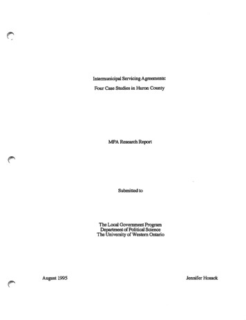
Aztec Classic Electric BoilersMODELElectrical InputSupply Current (amp)RCD Rating (amp)Minimum Cable Size (mm)Weight (kg)Water Content (litres)Width (mm)Depth (mm)Height (mm)Mains SupplyAztec2kW2kW8.5A13A17.01.0164130550Max Operating PressureTest PressureBoiler Flow TemperatureLimit ThermostatCasing FinishAztec6kW6kW25A32A48.12.1164130823Aztec Aztec Aztec9kW 11kW 12kW9kW 11kW 4164164130130130107310731073230V 50Hz3 bar43.5 psi6 bar87 psiAdjustable between 35 C and 75 C,located on the front casingFactory set at 100 CStove enamelled white8. Installation Instructionsenable the removal of the front casing. In both cases, where anyadditional equipment like a hot water cylinder or system controlsare to be fitted after the boiler has been installed, attention shouldbe give to ensure that they do not restrict access to the boiler forservicing.2Hot WaterCylinderMIN1501MIN DISTANCE150MM7. Technical SpecificationFIG. 18.1 Regulations8.4 Unpacking the BoilerInstallation of the boiler must comply with the following BritishStandards and Regulations:BS 5449 – Forced Circulation Hot Water Central Heating Systems.BS 7074 – Part 1 – Code of Practice for Sealed Water Systems.The Building RegulationsCurrent I.E.E RegulationsLocal water undertaking By-LawsCarefully open the boiler carton, remove boiler and place in a safeplace until required.8.2 Health & Safety at Work ActThe installer should be aware of his responsibilities under the Actand provide where necessary, appropriate protection for personscarrying out the installation. In the interests of safety a competentengineer should install the boiler and all wiring must be carried outin accordance with current IEE wiring regulations.IMPORTANT:ALL ELECTRICAL WORK MUST BE CARRIED OUT BY A QUALIFIEDELECTRICAL ENGINEER TO CURRENT IEE WIRING REGULATIONS.8.3 Siting the BoilerIMPORTANT: NOT TO BE INSTALLED IN A SHOWER COMPARTMENTOR BATHROOM.NOTE – ALWAYS STORE THE BOILER IN A DRY PLACE PRIOR TOFITTING. DO NOT ALLOW THE BOILER TO BE STORED WITH THECASING REMOVED.8.5 Fixing Boiler to the WallImportant:DO NOT CUT FLOW AND RETURN PIPES1. The boiler should be fitted to a suitable wall in an uprightposition. Flow tapping must be at the top of the boiler.2. Using fixing dimensions supplied work out position of boiler,mark four mounting holes and drill 6mm diameter to a depth of38mm.3. Fit plastic wall plugs into holes and fit bottom two mountingscrews.4. Hang on bottom two screws and push the boiler back towardsthe wall and secure in position with top two fixing screws. Theflow tapping must be at top of the boiler (continued on Page 7).TOP BRACKETFLOWTOP CASING CAPThe boiler is designed to be fitted in an upright position only.Ensure adequate clearance is allowed for making water connectionsas the boiler can be fully serviced from the front. The boiler mustalso be fitted in a dry well ventilated position, which is not subject toadverse temperature conditions (see Ventilation requirements).Care should be taken when siting the appliance to make sureadequate access is available for future servicing of the appliance.Please not the PCB and heat exchanger assembly may requireremoval during such times.When installed in a compartment with a hot water cylinder (see Fig.1), we recommend that the boiler is fitted in position 1; if fitted inposition 2, provision should be made at the front of the boiler toSIDE VIEWFRONT VIEWFIG 2FIG. 26
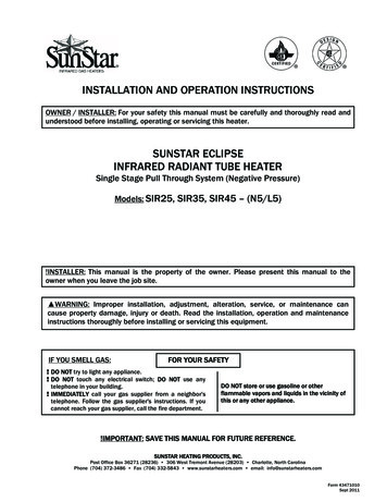
Aztec Classic Electric BoilersABCDECA B2kW5665865501071646kW839859823107164Fitting StrainRelief Bushes9-12kW108911091073107164MINIMUM CLEARANCES:FRONT – 150mmFrom other fixed equipment:TOP – 100mmBOTTOM – 100mmL/H SIDE – 50mmR/H SIDE – 100mmNOTE: APPROXIMATELY 750mm WILLBE REQUIRED AT THE FRONT OF THEAPPLIANCE TO ENSURE ADEQUATEACCESS BY AN ENGINEER DURINGROUTINE SERVICING.Strain ReliefBushesFIG. 58.6 Ventilation RequirementsDEFIG 35.Removing four casing screws and washers will allow casing tobe removed.6. Slide top casing cap upwards this will allow front casing to slideforward.7. With the front casing removed fit three strain relief bushes intobase of back panel.8. Fit pipe sealing grommet into top casing panel and cut off endto allow pipe to slide through (See Fig. 4).IMPORTANT: TOP CASING PANEL WITH GROMMET MUST BE REFITTED BACK IN POSITION BEFORE MAKING TOP PIPECONNECTION. ALTERATION OR FAILURE TO COMPLY WILLINVALIDATE THE WARRANTY.9. When re-fitting casings slide front casing back into positionensure small temperature adjuster on PCB passes through thehole on the control panel. Slide the top-casing panel down intoposition and secure panels into position using the four screws.If the appliance is to be fitted in a confined space or compartmentwith a potential ambient temperature of 60 C or above, it is stronglyrecommended that adequate ventilation is provided to prevent the2overheating of the boiler controls. Aeration of 100cm will berequired to the compartment, in both high and low level positions.100cm2AztecElectricBoilerFitting pipe Seal100cm2FIG. 6Top CasingPipe SealFlow PipeFIG. 4Temperature control Buttons should be connected with the suppliedcable to the 4 pins on the Circuit Board above the GREEN LED8.7 Water SystemsIMPORTANT: USE ONLY COMPRESSION FITTINGS WHENCONNECTING THE BOILER TO THE CONTRAL HEATING SYSTEM.The installation must comply with the requirements of the followingcodes of practice.BS 5449 Part 1 Forced Circulation Hot Water Systems.BS 7074 Part 1 Code of Practice for Sealed Water Systems.BS 7593 Treatment of Water in Domestic Hot Water Central HeatingSystems.7
Aztec Classic Electric BoilersThe water system must be thoroughly flushed out with cold waterwithout the pump in position. Refit the pump and fill the system.Vent all air from the system. Clear any air locks and examine thesystem for water leaks.IMPORTANT: ENSURE ALL SERVICE VALVES ARE IN OPEN POSITION.Ensure boiler is fitted with flow pipe at the top and return pipe atthe bottom.The boiler is supplied with 22mm tail pipes top and bottom forconnection to the system.The boiler must be installed using 22mm compression fittings bothtop and bottom.The AZTEC ranges of boilers are low water content boilers so requirea good flow rate at all times (see below chart).ModelAztec 2kWAztec 6kWAztec 9kWAztec 11kWAztec 12kWMin Flow Rate/Min4 Litres8 Litres10 Litres11 Litres12 LitresAztec boilers are approved for use on fully pumped open ventedsystems and sealed systems. When fitting on a sealed system a 3 barsafety valve must be fitted to the system, where thermostaticradiator valves are fitted it will be necessary to fit a bypass to obtainminimum flow rates.IMPORTANT: IF MIN FLOW RATES ARE NOT OBTAINED THE BOILERMAY GO TO LOCK OUT ON HIGH LIMIT THERMOSTAT.Where more than 1 boiler is fitted refer to multiple boilerinstallations.System must be flushed out before adding inhibitor to BS 7593:1992Treatment of Water in Central Heating Boiler.IMPORTANT: THIS BOILER IS TO BE FITTED ON FULLY PUMPEDSYSTEMS ONLY.Sealed Water System RequirementsThe installation must comply with the appropriate requirements ofthe current issue of BS 4814, BS 5449, BS 6798 and BS 7074 Part 1and 2.THE INSTALLATION ENGINEER MUST BE REGISTERED AS ACOMPETENT UDHWSS INSTALLER.Safety ValveA safety valve set at 3 bar must be fitted with the drain routed tothe outside of the building. The drain must not discharge above anentrance or a window or any public access area, be clear of anyelectrical fittings and positioned so that any discharge can be seen.Expansions Vessel CapacityA diaphragm type expansion vessel, conforming to the current issueof BS 4814. The expansion vessel must be connected to the systemsat a point close to the inlet side of the circulating pump. Theexpansion vessel volume depends on the total water system volumeand the initial system design pressure. For any system an accuratecalculation of vessel size is given in the current issue of BS 5449 andBS 7074 Part 1.The water content of the boiler is given in the TechnicalSpecification. Note: A higher initial design pressure requires a largervolume expansion vessel.The charge pressure must not be less than the static head of thesystem that is the highest point of the system above the expansionvessel.Capacity of Expansion VesselWhere design information is not complete the following chart (Page9) can be used for selecting the size of the vessel, it should be notedthat the size given in the table account of fault conditions.System TemperatureThe normal running temperature of the system is 75 C, if a fault wasto occur then the safety device would allow the system temperatureto rise to 100 C. It is recommended that this figure be used in thecalculations of vessel size.Connection of the Expansion VesselThe expansion vessel should be connected in the neutral part of thesystem this being the return pipe work close to the boiler, refer tosealed system pipe work layout drawing (Fig 11).Pressure GaugeA pressure gauge must be permanently fitted in the system coveringa range from 0 to 4 bar. Position where it can be seen when fillingthe system.InhibitorIf using an existing system, take care to drain down the entiresystem including the radiators then thoroughly clean out beforefitting the boiler. Attention is drawn to the current issue of BS 5449and BS 7593 on the use of inhibitors in central heating systems.Drain TappingA drain tapping must be provided at the lowest point of the system,which will allow the entire system to be drained.Note: Failure to ensure the correct vessel size could result inpremature failure of the expansion vessel which in turn mayadversely affect other components in the system i.e. circulatingpump and diverter valve.System Make-UpWater loss from the system should be replaced from a make-upvessel connected to the system. This vessel should be higher thanthe top of the system. Alternatively provision can be made by prepressurisation of the system via a temporary hose connection andthrough a double check valve (non-return) and stop valve. Theremust be no permanent connection to the mains water supply eventhrough a non-return valve.Alternative Methods of Filling Sealed SystemMETHOD VACUUMVALVEHOSEUNIONSMAINSWATERSUPPLYSTOPVALVETEST COCKMAINS WATERSUPPLYCISTERN &OVERFLOWFIG 7TEMPORARYHOSEPRESSURE PUMP &REDUCING VALVE IFREQUIREDSTOPVALVEHEATINGSYSTEM(RETURN)8
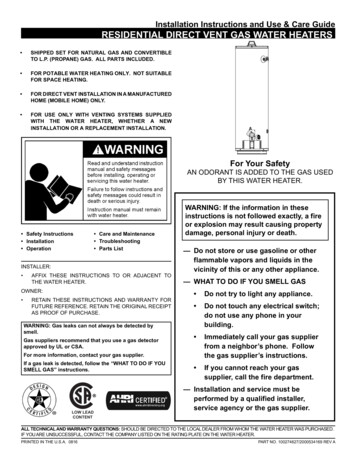
Aztec Classic Electric BoilersØ28mmØ22mmØ35mmØ28mmØ22mmMin. FlowRateØ22mmFIG 8Safety valve setting (bar gauge)Vessel charge and initial systempressure (bar gauge)Total water content of systemLitre2550751001251501752003 bar0.51.0Litre2.34.47.09.411.714.116.418.8Vessel 1.447.4Ø22mmØ28mmØ22mmValveFIG 99. Multiple Boiler InstallationsImportantWhere a greater output is required, more than one boiler can beused in the same system. However, if installing a circulating pumpwith a higher power demand, the PCB circuit protection fuse maynot be adequate. The pump could be wired using a relay. See wiringinstructions (Page 12, Fig 13-15) for further details.The boilers must be fitted side by side using common flow andreturns. For each additional boiler fitted, it is recommended that thepipe work is increased in size and the pump set to deliver thecombined flow rates. The circulating pump will be connected to oneof the boilers or via the relay.We strongly recommend the positioning of isolation valves on theflow and return pipe work of each boiler, as there may be a need toisolate one or more during servicing (see Fig.9).Please contact the Technical Support team for further information.9
Aztec Classic Electric BoilersOpen ventedF&E TankarrangementØ22mmAuto air ventOpen Vent SystemDHW CylinderAuto air vent500mm (min)Ø15mm3 port valvePUMPService valveAztec BoilerFLOWBypass mustdissipate heat andbe 22mm diametermin x RETURNService valveDrainvalveFIG 10Auto airventSealed SystemDHWCylinderAuto airvent3 portvalveCentral heatingAlternativepump positionServicevalveAztec BoilerFLOWBypass mustdissipate heat andbe 22mm diameterAutobypass min x 1.5mtrvalvePressureGaugeSafetyvalveServicevalveFIG 11RETURNPUMPDrainvalveExpansionvessel10
Aztec Classic Electric Boilers10. Wiring InstructionsALL ELECTRICAL WORKMUST BE CARRIED OUT IN ACCORDANCEWITH CURRENT IEE WIRING REGULATIONS.BEFORE COMMENCING INSTALLATION CHECK POWER SUPPLY TOTHE PROPERTY TO ENSURE THAT THERE IS SUFFICIENT CURRENTAND VOLTAGE AVAILABLE FOR SIZE OF BOILER BEING FITTED. TAKEINTO ACCOUNT REQUIREMENTS OF OTHER ELECTRICALAPPLIANCES. THE BOILER MUST BE CONNECTED TO THE MAINSSUPPLY BY MEANS OF A DOUBLE POLE LINKED SWITCH WITH 3mmCONTACT GAP IN BOTH POLES.IMPORTANT: After completing electrical installation workpreliminary safety checks should be carried out as described in BS7671:2001.Important:The electrical supply requirements:The 2kW boilers and 6kW boiler supplies should meet therequirements of EN 61000-3.3.The 9kW and 11kW boilers must be installed in premises having aservice supply of 100A per phase and meet the requirements of IEC60417-5855.The 12kW boiler must be installed in premises having a systemimpedance of not more than 0.1939 0.1939Ω.A double pole RCD with trip level sensitivity of 30mA can be usedcapable of breaking full load current to BS EN 61008:1994.Note: RCD UNIT can be used as the isolating switch if mounted closeenough to the boiler.Miniature circuit breakers (MCB) MUST be fitted between RCD unitand boiler and RCD and any external controls. Refer to technicalspecification. For MCB ratings refer to wiring diagram.It is important the correct size MCB is used in the supply from theRCD to the boiler. An additional MCB rated 6A will be required tosupply the external controls.Electrical ConnectionsWARNING: THIS APPLIANCE MUST BE EARTHED.The mains connection block is located inside the boiler on a bracketat the top left hand side of the boiler which can be directly wired tothe boiler MCB. Use the correctly rated cable.Where the pump is wired directly back to the boiler both live andneutral connections must be used with the earth being wired backto the earth post. This is important as the pump is controlled by aswitched neutral. This also applies to pumps being controlled by arelay.IMPORTANT: CORRECT POLARITY MUST BE OBSERVED WHENBRINGING THE MAINS SUPPLY INTO THE BOILER.Temperature control Buttons should be connected with the suppliedcable to the 4 pins on the Circuit Board above the GREEN LUENREDBOILER PCB CONTROLWIRING FOR EXTERNAL PROGRAMMERFIG. 1211
Aztec Classic Electric BoilersWiring Instructions (continued)230V SUPPLYGREYORANGE3 Phase Supply Connections for 2 or more BoilersCALL TERMINAL(BOILER)MAINS SUPPLY CABLESConnect each boiler to each phase.CONTROL SIGNALWire as shown in wiring diagram.PLEASE NOTE: THIS LIVE SUPPLYCAN ONLY RE USED FOR THISWIRING CONFIGURATION. ANYOTHER USE MAY RESULT INDAMAGE TO THE PCB.PUMP CONNECTIONSThe pump to be connected to one boiler only.See wiring diagram.IMPORTANT: ALL ELECTRICAL CONNECTIONS SHOULD BE CHECKED,LOOSE CONNECTIONS CAN CAUSE PROBLEMS.PROGRAMMABLE ROOMSTATWARNING: THIS APPLIANCE MUST BE EARTHED.2.Any exposed pipe work must be earthed in accordancewith IEE regulations.On completion of installation all electrical work must betested to IEE regulations and NICEIC inspection andcompletion certificate must be issued.PUMPREDFIG. 14CALL BOARD 1CALL BOARD 2 CALL BOARD DABCRELAYCONTROLLERP
CLASSIC 2, 6, 9, 11 & 12KW BOILER INSTALLATION, OPERATION AND SERVICING INSTRUCTIONS . The Aztec electric boiler is a wall mounted electric central heating boiler designed with smaller properties in mind. Fitted vertically only and requiring access to the front and the right hand side of the boiler FOR SERVICING. .