Transcription
FAULT FINDING,MAINTENANCEANDDIAGNOSTIC SKILLS1
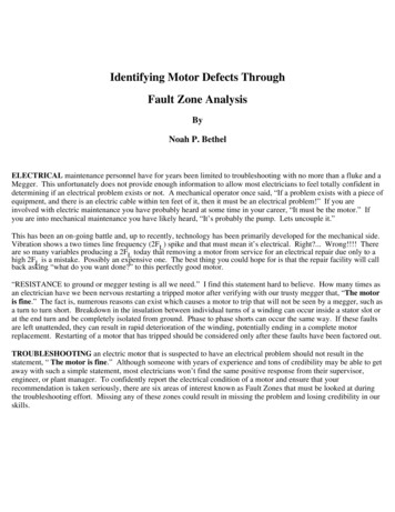
General Principles of Fault FindingIn this section we look at the general principles of fault finding through the application of diagnosticreporting. These principles apply in all disciplines regardless of whether they are civil, electrical,mechanical etc.Principles of Systematic Fault DiagnosisDiagnosis of faults requires a logical and disciplined approach. Frequently, past experience ordetailed knowledge will help. Also an intuitive approach can be used but must be accompaniedby a deductive technique. Faults can be classified as: Positive fault sustained fault Intermittent fault irregular, harder to findTools for the JobYour standard of work is related to the quality and completeness of the tools available to you.Traditionally this has been: Trade skill Knowledge of plant Problem solving abilityToday your ability to diagnose and repair faults largely depends on levels of documentationand test results.DocumentationDocumentation should be: Aimed at the level of the maintenance Structured in a standard format Logical, precise and factual no irrelevant materialTest FacilitiesFacilities for testing equipment are often limited. However it is desirable that plant users specify(when able to) what is required to make the system maintainable by means of diagnostic methods.Plant manufacturers will often build test points into the system. To do so later becomes veryexpensive. Built in test facilities are generally for first line maintenance staff, such as lamps,pressure gauges, multi meters etc.The Logical Diagnostic ProcessExperience shows, paradoxically, that the faster a maintainer acts to identify a fault the morelikely that he/she: fails to find it disguises it makes it worseThe first golden rule of fault diagnosis therefore is:STOP AND THINKConsider the problem then collect and evaluate the facts. The fundamental steps in the logicaldiagnostic process for all type of equipment are:(1) Symptom analysis(2) Equipment Inspection(3) Fault stage location(4) Circuit checks(5) Repair or replace(6) Perform test2
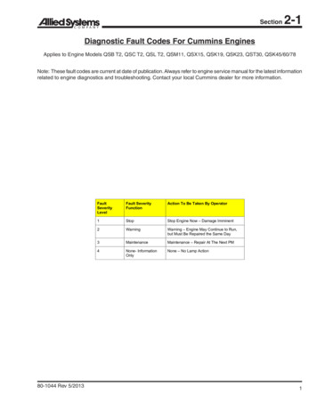
STEP 1: SYMPTOM ANALYSIS1. Question operator2. Observation3. Inspect monitors4. Run equipmentSTEP 2: INSPECT EQUIPMENT1. Take a closer look2. Utilizes natural senses3. Continue collecting evidence4. Evaluate findingsSTEP 3: FAULT STAGE LOCATION1. Consult or construct FaultSystem Diagram2. Determine system structureand test strategy3. Systematic testing4. Locate faulty stage andcauseSTEP 5: REPLACE OR REPAIR1. Draw new part and fit sameOR2. Repair on siteSTEP 6:Conduct performance checksHave youlocated thefaulty unit?YesIs itSatisfactory?NoSTEP 4: CIRCUIT CHECKS Continueinvestigation using same test strategyuntil defective unit and cause locatedYesReturn to serviceFigure 1. Diagnostic process flow chart3No
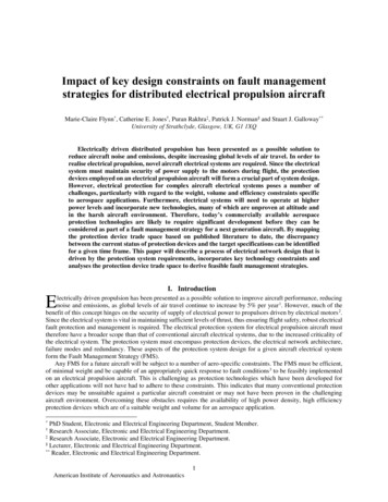
Electrical SafetyElectrical Troubleshooting can be hazardous. Ensure you take the proper precautions. Electricity has longbeen recognized as a serious workplace hazard, exposing employees to electric shock, electrocution, burns,fires and explosions.Troubleshooting RegulationsThere are numerous regulations, which have been developed to keep the worker safe while on the job.These regulations, which are typically developed by government and other regulatory bodies, can varyfrom region to region depending on the jurisdiction and even from company to company. Be sure you arefamiliar with the regulations that apply to you some of the things these regulations may address are: What distance you must maintain from live electrical apparatus. This distance is dependent on thevoltage level and training.What type of safety equipment must be worn when performing certain troubleshooting tasks?What type of test equipment must be used and under what conditions.What special work procedures are required to perform various tasks?What training is needed to perform various tasks? For example, a person with specific training isallowed to be closer to live electrical apparatus than an untrained person.Troubleshooting HazardsTroubleshooting can introduce many new safety concerns especially when inspecting equipment that isenergized. Testing often requires the troubleshooter to temporarily connect test instruments to “live”terminals, which may involve opening enclosures or cabinets that normally are locked or bolted closed toprotect workers. This introduces two main hazards:1. Shock Hazard. If you were to contact live equipment with your body or a tool you are holding thecurrent flowing through your body could cause severe injury, burns, and even death.2. Flash Hazard. If you are in the vicinity of equipment that fails and causes an electric arc, the flash,heat and shrapnel caused by the arc can also be life threatening.1. Shock HazardWhat causes shocks?Electricity travels in closed circuits, normally through a conductor, but sometimes a person’s body an efficientconductor of electricity mistakenly becomes part of the electric circuit. This can cause an electrical shock.Shocks occur when a person’s body completes the current path with: both wires of an electric circuit; one wire of an energized circuit and the ground; A metal part that accidentally becomes energized due, for example, to a break in its insulation.When a person receives a shock, electricity flows between parts of the body or through the body to aground or the earth.What effect do shocks have on the body?An electric shock can result in anything from a slight tingling sensation to immediate cardiac arrest.The severity depends on the following: the amount of current flowing through the body, the current’s path through the body, the length of time the body remains in the circuit, and the frequency of the currentThe following table shows the general relationship between the amount of current received and thereaction when current flows from the hand to the foot for just 1 second.Physiological Effects of Current on the Body4
Protecting Against Shock HazardsElectrical equipment is generally designed to minimize electrical hazards. This is normally done through: The use of guards and barriers, Grounding of equipment cases Use of proper insulation Installation of protective electrical devicesHowever, the hazards cannot be totally eliminated. You may have to replace equipment, open an enclosureor even perform tests on live equipment.In order to protect you from these hazards, safe work practices have been developed. Some examplesare: de energizing electric equipment before inspection or repair, keeping electric tools properly maintained, exercising caution when working near energized lines And Using appropriate protective equipment.Following safe work practices is an important way that you can protect yourself from electrical hazards.Lockout/Tag outOne work practice that is extremely important to the trouble-shooter because of the testing and repairwork performed is Lockout/Tag out. Here is what OSHA says about Lockout/Tag out.Proper lockout/tag out procedures protect you from the dangers of the accidental or unexpected start-upof electrical equipment and are required for general industry by OSHA (Occupational Safety and HealthAuthority) Standard 1910.333, Selection and Use of Work Practices. Requirements for constructionapplications are in 29 CFR 1926.417, Lockout and Tagging of Circuits. These procedures ensure thatelectrical equipment is de energized before it is repaired or inspected to protect you against electrocutionor shock.The first step before beginning any inspection or repair job is to turn the current off at the switch box andpadlock the switch in the OFF position. This applies even on so-called low-voltage circuits. Securely tagging5
the switch or controls of the machine or equipment being locked out of service clarifies to everyone in thearea which equipment or circuits are being inspected or repaired.Only qualified electricians who have been trained in safe lockout procedures should maintain electricalequipment. No two of the locks used should match, and each key should fit just one lock. In addition, oneindividual lock and key should be issued to each maintenance worked authorized to lock out and tag theequipment. All employees who repair a given piece of equipment should lock out its switch with anindividual lock. Only authorized workers should be permitted to remove it.2. Flash HazardsIf you are familiar with electric arc welding, then you are aware that the small arc created by the weldingequipment can generate enough heat to melt metal as well as generate enough UV rays to burn your skin.In the case when electrical equipment fails causing an electrical arc, the energy released during the arcingcan be many, many times greater than the welding arc and can cause severe flash burns. The burns fall intoone of three categories: First Degree: the outer skin layer is damaged, it is painful, but since the growth areas are notdamaged, the skin is quickly regrown and no scarring is left. Second Degree: the outer skin layer is severely damaged and blistering usually occurs. Healing is muchlonger as it occurs from the deeper sweat glands and hair follicle areas. Scarring is often the result. Third Degree: complete destruction of the skin and growth areas. If the burn is small healingmay occur from the sides, however skin grafting is usually required.Protecting Against Flash HazardsHard hats, safety glasses, gloves and work boots with electrical insulation rating give the worker protectionduring normal work, however in the event of circuit or switchgear failure resulting in a thermal arc beingcreated, much greater protection is required.The following is some general information on protecting against flash hazards. Be sure to review theappropriate legislation and your company policies before attempting to work near live electrical apparatus. Flash Protection ClothingClothing can be made from many different materials. These materials have an Arc Thermal PerformanceExposure Value (ATPV) associated with them which is defined as the amount of heat energy that the fabricwill handle deflect or absorb. Some of these materials offer better protection against the heat caused froman arc than others.Here are some examples Synthetic material like nylon, rayon or polyester should never be worn when working on or nearenergized electrical equipment because it is flammable and has a tendency to melt and stock to skinwhen exposed to high temperatures.Cotton blends with synthetic material should not be worn near electrical equipment for the samereasons.Pure cotton provides a minimum barrier to arc temperatures, but can ignite quickly. It does6
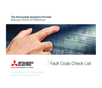
burn and fall away rather than stick to the skin.Materials like cotton or cotton blends treated with a flame retardant chemical provide aminimum level of flame resistance. Some chemical treatment degrades with repetitivelaundering.In general, all clothing including undergarments should be 100% cotton. Flame resistant clothing shouldthen be worn over this when working on or near energized electrical equipment. When combined in layers,the fabrics gain significant rating from the air space between them, and multiple layers have much higherratings than the sum of the individual ratings. Safety GlassesFor normal work clear lenses are adequate, however for flash protection like that required for live work,troubleshooting, switching and applying or removing grounds, then flash rated eye protection is required.In some cases full face protection is required. Other PPE (Personal Protection Equipment)Other specialized personal protective equipment may be required when performing work where a flashhazard is present. Some examples are: fire resistant hard hat liner, leather gloves, hearing protection andleather work shoes. Identifying Shock and Flash HazardsBefore working on or even opening an electrical enclosure you should know what the hazards are and howto protect against them. Some regulations are now requiring that all enclosures are labelled with the levelof protection required and distanced to maintain when working on or near equipment contained in anenclosure. An example is shown here.Some types of labelling also show the following information: Flash Hazard Boundary Cal/cm2 Flash Hazard at 18 inches PPE level (what type of personal protective equipment is required) Approach Boundaries to Live Parts for Shock Protection.A Final Note:Here are some tips to help you safely troubleshoot electrical equipment: Be informed, be aware of the Hazards, Make sure you know and understand all the rulesand regulations that apply to the work you are doing. These can be governmentalregulations or policies and procedures produced by your company. Follow all safety rules and procedures, these are designed to protect you. Don’t take shortcuts. Use the troubleshooting simulator in this program to practice your troubleshooting skills in asafe environment. Wear all required personal protective equipment, In the event of equipment failure oraccidental contact, your personal protective equipment may save your life.Fault finding proceduresHaving established the symptoms of a fault it is then necessary to conduct tests to confirm the symptoms andto attempt to determine the location of the fault within the equipment. A sound knowledge of the technicalconcepts and the operation of the system may assist in locating the fault but sometimes the testing will beextensive and an overall procedure should be adopted.7
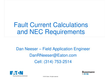
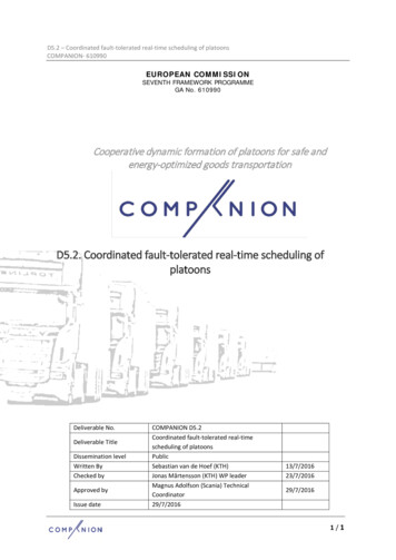
Fault Finding liability basedSystematicFunctional structure basedInput to outputOutput to inputHalf-splitFigure 8. Fault finding proceduresBasic Testing TechniquesThe MultimeterOnce you have determined the most probably cause of a fault, you must either prove it to be the problem ornot. This can sometimes be done by careful inspection but in many cases the fault will be such that youcannot identify the problem component by observation and analysis alone.Here, test instruments can be used to help narrow the problem area and identify the problemcomponent.General Meter RulesThere are many types of test instruments used for troubleshooting. Some are specialized instrumentsdesigned to measure various behaviors of specific Equipment. There are other types of test instruments suchas multimeters which are more general in nature and can be used for most electrical measurement. A typicalmultimeter can measure AC and DC Voltages, Resistance and Current.Before you use a meter to make a test you should know what the meter will read if the circuit is operatingnormally. You should make your prediction of the reading expected, based on the circuit schematic. If thereading is anything other than your predicted value, you know that this part of the circuit is being affected by8
the fault.You should always check the meter before using it to troubleshoot. For a voltmeter, test the meter on a known voltage source before using. Your meter shouldread the correct voltage. For an ohmmeter, touch the meter leads together. The display should read 0 ohms or very nearthis. With the leads apart it should read OL (infinity).Meter PrecautionsHere are some more Do’s and Don’ts for using a meter. Be familiar with its features. Read the instruction manual before using. Ensure it is safe to use – no obvious damage to the meter or the meter leads. Be sure the test leads are in the correct sockets and the rotary switch is in the correct position forthe desired measurement. Never measure resistance in a circuit when power is applied. Never apply more than the rated voltage between any input jack and ground. Keep your fingers behind the finger guards on the test probes when making measurements. To avoid false readings, which could lead to possible electric shock or personal injury, replace thebattery as soon as the battery indicator appears.Testing Live vs. DeadOne of the first things you must decide is whether the circuit can be alive or must be dead while testing.Performing certain tests while a circuit is alive can be very helpful. However, some companies havepolicies that ban (or restrict) testing live circuits while troubleshooting. Before doing any testing makesure you check your company’s policy. This module does contain certain techniques used to test a deenergized circuit.Types of FaultsFaults can generally be categorized into either open circuits or short circuits. Open circuits occur whenthere is a break in the circuitry. This could be a broken wire, loose connection, burned out component,etc. Short circuits occur when two or more components, which should be isolated, come in contact with each other.For example, the insulation on wiring could decay and the conductors short together or short to ground9
Sectionalizing Circuits with MetersSometimes you will be faced with a problem that there are few useful observations and the problem area is alarge portion of the circuit. It may not be feasible to begin testing all the components in the problem area. Youshould still start with the component you identified as the most probable cause. If this component is not theactual cause, the meter readings will provide you with information that reduces the size of the problem areaand points you in the direction of the fault. This is called sectionalizing. The meter techniques described in thissection use this concept in determining where to test.Using a VoltmeterVoltmeters are the best tool to use for finding open circuits – if you can safely turn the power on. Once you know itis an open circuit and have determined the general area of the fault, get your voltmeter out and check that it isworking on a known source.Connect the negative lead to a known reference. The negative (neutral or ground if on AC) supply is preferable. Testthrough the affected circuit with your other lead, making sure all necessary switches are closed. The wire or devicebetween the last point you test full voltage and the first place you don’t get full voltage is where the open circuit islocated.Don’t forget about checking the neutral path. When you get full voltage at the positive terminal of a device that issupposed to be operating and isn’t, don’t stop! Carry on through the return path (Negative or neutral).10
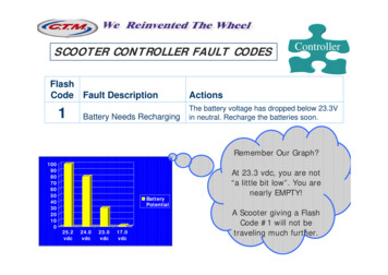
Using an OhmmeterWhen using an ohmmeter you must first shut off and lock out the power supply.Using a connection wiring diagram, determine the location of the component which you feel is the mostprobable cause. Next disconnect a wire from the component which will eliminate possible parallel paths andthen test for continuity. You should be careful to identify any wires you disconnect and be sure they arereconnected in the proper locations. When making your tests you should connect one meter lead to eitherside of the open point and then test across the component, or to ground.Fig-Some Ohmmeter Connection OptionsUsing an Ohmmeter to find Short CircuitsShort circuits allow voltages and currents to flow in the wrong parts of a circuit, which causes malfunctions.These tend to be easier to find with an ohmmeter. The most common type of short circuit is a short toground.To find this type of fault, first lock out the circuit. Next disconnect and remove a wire at the component youhave identified as your most probable cause. Then connect one lead of the ohmmeter to a ground point andthe other lead to the suspected component. If your meter reads very low, then the fault is below the openpoint. Otherwise the fault is above the open point.Reconnect the wire and disconnect another in the direction of the fault. Take the readings, Continue this11
process until the meter no longer sees the fault. The last component tested is therefore the cause of thefault.Using an Ohmmeter to find Open CircuitsSometimes you can’t energize a device for testing even though the fault is an open circuit.Here, you have to use an ohmmeter.To find this type of fault, first lock out the circuit. Next disconnect and remove a wire at the component youhave identified as your most probable cause. Then connect one lead of the ohmmeter to a ground point andthe other lead to the suspected component. If your meter reads infinity, then the fault is below the openpoint. Otherwise the fault is above the open point.Reconnect the wire and disconnect another in the direction of the fault. Take the readings. Continue thisprocess until the meter no longer sees the fault. The last component tested is therefore the cause of thefault.Using an AmmeterWith an ammeter, you can measure the current flowing through a circuit. This can be very useful when yourother test instruments (voltmeter and ohmmeter) are not appropriate. For example, measuring the currentin each phase of a 3 phase motor can provide very important clues as the motor behavior.There are two ways to use an ammeter.The first way is to connect the meter leads into the appropriate sockets on the meter and then insert themeter into the circuit. To do this you must first lockout the circuit, disconnect a terminal where you want totest and then connect the leads between the terminal and the wire as shown. When using this method youmust be sure that the current you are about to measure will not exceed the maximum value for the meter.Another option for measuring current (AC current only) is to use a clamp-on probe instead of the meterleads. One end connects into the appropriate sockets on the meter and the other end consists of a springoperated circular clamp, which can be clamped around a wire. The clamp is really a small transformer thatcan sense the current flowing through the wire and send this information to the meter to be displayed.This type of reading has the advantage that you do not need to disconnect any wires inthe circuit. This type of ammeter is used in Smutch’s troubleshooting simulators.12
Basic Methods of Fault Diagnosis DocumentationIn this section we will look at three basic methods used for diagnostic documentation.These are:a) Symptom chartsb) A l g o r i t h m chartsc) Functional chartsStructured Functional Block DiagramsThis form of diagnostic aid is based upon the use of block diagrams designed to describe the completesystem or sub-system. Such diagrams show the logical interconnection and interaction between thevarious parts of the system. The various blocks on such diagrams represent identifiable functions and arecalled ‘functional blocks’.By definition, a function is an activity to modify something; it is intrinsically complete and contains allnecessary services. It acts on the logic flow-path which maybe: Feedstock Control signals Service suppliesThis approach often uses a nested hierarchy of block diagrams (as shown in the following diagram)together with a set of accompanying test data sheets. The top level diagram describes the overall systemwith the selection of functions represented on the diagram sufficient to permit the fault to be isolated towithin a single major functional breakdown of each of the blocks on the following diagrams. This processis repeated until generally we are down to a particular printed circuit board, hydraulic valve etc. At thispoint the maintainer must be advised what to do.13
Test InformationEach logic diagram must be accompanied by a test data chart. Also there must be sufficient test pointson the equipment.Information on the functional block should tell the maintainer what the function does and when itdoes it. It should not tell him how it works.Repair PolicyThe repair policy associated with this technique is normally the replacement of faulty modules. The repair ofmodules is carried out in a workshop by more skilled labor or by the manufacturer. This requires suitablecontrol and supervision of stockholding and repair turnaround of faulty modulesDown Time and Repair Time(a) Realization TimeThis is the time which elapses before the fault condition becomes apparent(b) Access TimeThis involves the time, from realization that a fault exists, to make contact with displays and testpoints and so commence fault finding. This does not include the time to travel to the site, but the timerequired for removal of covers and shields and the connection of test equipment. This is determinedlargely by mechanical design(c) Diagnosis TimeThis is referred to as fault finding and includes adjustment of test equipment (e.g. Setting upan oscilloscope or generator,) carrying out checks (e.g. Examining waveforms for comparisonwith a handbook), interpretation of information gained (this may be aided by algorithms),verifying the conclusions drawn and deciding upon the corrective action and in no specificsequence(d) Spare Part ProcurementPart procurement can be from the “tool-box”, by cannibalization, or by taking a redundant identicalassembly from some other part of the system. The time taken to move parts from a depot or store to thesystem is not included, being part of the logistic time(e) Replacement TimeThis involves removal of the faulty LRA (Least Replaceable Assembly) Followed by connection andwiring, as appropriate, of a replacement. The LRA is the replaceable item beyond which fault diagnosisdoes not continue. Replacement time is largely dependent on the choice of LRA and on mechanicaldesign features such as the choice of connectors and fittings(f) Checkout TimeThis involves verifying that the fault condition no longer exists and that the system is operational. Itmay be possible to restore the system to operation before completing the checkout in which case,although a repair activity, it does not all constitute down time(g) Alignment TimeAs a result of inserting a new module into the system, adjustments may be required. As in the case ofcheckout time, some or all of the alignment may fall outside the down time(h) Logistic TimeThis is the time consumed waiting for spares, test gear, additional tools and manpower to betransported to the system(i) Administrative TimeThis is a function of the system user’s organization. Typical activities involve failure reporting (wherethis affects down time,) allocation of repair tasks, manpower changeover due to demarcationarrangements, official breaks, disputes, etcActivities (b) (g) are called Active Repair Elements and activities (h) and (i) Passive RepairElements.Realization time is not a repair activity but may be included in the MTTR1 where down time is theconsideration.14
Checkout and alignment, although utilizing manpower, can fall outside the down time.The Active Repair Elements are determined by design, maintenance arrangements, environment,manpower, instructions, tools and test equipment.Logistic and Administrative time is mainly determined by the maintenance environment, that is to say, thelocation of spares, equipment and manpower and the procedures for allocation tasks.Effecting RestorationField or Workshop RepairAs a trouble-shooter, at some point or other, you will have to decide whether to send components to aworkshop for repair as opposed to carrying out repairs on-site. Sometimes such a decision is simple, forexample the work cannot be done on-site or special transport units may not be available in an acceptabletime or the repair is essential for survival. At other times there may be a fine balance between choosingworksite or workshop repairs.The following factors should be taken into account when making the decision on repair site: Availability of resources, that is, workshop, equipment and transport. Cost of workshop time. Transport costs of defective item versus repair equipment and staff. Time loss and production losses. Expertise availability. Availability of stores and parts. Coincidental advantage, for example, the machine was almost due for routine overhaul, or isgenerally debilitated and in need of other repairs. Requirement to set up clean areas, etc. Accessibility of worksite.Accommodation costs and availability.Other considerations not specific to the job in hand are sometimes taken into account, for example,potential training advantages, cost-effectiveness audit, public relations or company prestige.There is another factor that may preclude certain choices availability of funds. This is particularly true ofsmaller companies whose overall maintenance reserves have become depleted.One “game” which may be useful in forward planning is the “What if?” game. This game consists of a seriesof simple questions for which you must prepare answers.“What if the diesel engines fail catastrophically? How would that fit into the list above?” “What if this itemof repair equipment was purchased? How would that affect project repair capacity?” and so on.The advantage of such an exercise is that you are in some ways prepared for many of the events that canplague an operation and can respond in an efficient manner. This is, or should be, a standard managementplanning routine for any operation. It should also be carried out by the on- site management staff or withtheir expertise available.Assuming you have done your groundwork effectively, and have coasted a job with relative accuracy,then you should be in a position to evaluate the cost-effectiveness of worksite versus workshop repairswhile taking into account all other advantages.Short term repairFactors considered in deciding whether to affect a short term repair should include the following overrides: Safety must never be compromised. No legal requirements should be violated. System integrity should be maintained.15
If the above factors are met, then our choice as to whether to effect a short term repair becomes one ofcost effectiveness. In evaluating this we may have to look at the cost of undoing the repair.An example of a temporary repair might be the seal welding of flanges or other normally bolted items.The cost of replacement may exceed the advantages gained.Overriding a running aid may result in an increase of workload for already pressed operators or anincrease in sta
Today your ability to diagnose and repair faults largely depends on levels of documentation and test results. Documentation Documentation should be: Aimed at the level of the maintenance Structuredin a standard format Logical,precise and factual no irrelevant material Test Facil