Transcription
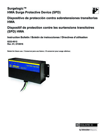
Surgelogic HWA Surge Protective Device (SPD)Dispositivo de protección contra sobretensiones transitoriasHWADispositif de protection contre les surtensions transitoires(SPD) HWAInstruction Bulletin / Boletín de instrucciones / Directives d’utilisation8222-0012Rev. 01, 07/2016Retain for future use. / Conservar para uso futuro. / À conserver pour usage ultérieur.
HWA Surge Protective Device (SPD)ENGLISHTable of ContentsPrecautions . 3Introduction . 4Unpacking and Preliminary Inspection . 5Storage . 5Identification Nameplate . 5SPD Location Considerations . 5Environment . 5Audible Noise . 5Mounting . 5Service Clearance . 5Equipment Performance . 5Electrical . 6Voltage Rating . 6Wire Leads . 7Branch Circuit Overcurrent Protection and Disconnect Means . 7Location of Surge Protective Device (SPD) . 8System Grounding . 9Installation . 10Mounting Recommendations . 10Wiring . 11HWA Wiring Diagrams . 12Operation . 13LED Status Indicators . 13Audible Alarm . 13Dry Contacts . 14Remote Monitor Option . 15Preventive Maintenance . 162 2002–2016 Schneider ElectricAll Rights Reserved / Reservados todos los derechos / Tous droits réservés8222-0012
Rev. 01, 8222-001207/2016HWA Surge Protective Device (SPD)PrecautionsPrecautionsENGLISHDANGERHAZARD OF ELECTRIC SHOCK, EXPLOSION, OR ARC FLASH Apply appropriate personal protective equipment (PPE) and follow safeelectrical work practices. See NFPA 70E. This equipment must only be installed and serviced by qualifiedelectrical personnel. Turn off all power supplying this equipment before working on or insideequipment. Always use a properly rated voltage sensing device to confirm power is off. Replace all devices, doors and covers before turning on power to thisequipment. This equipment must be effectively grounded per all applicable codes.Use an equipment-grounding conductor to connect this equipment tothe power system ground.Failure to follow these instructions will result in death or serious injury.CAUTIONLOSS OF BRANCH CIRCUIT POWER / LOSS OF SURGESUPPRESSION Perform periodic inspection of the SPD status indicator lights as part ofthe preventative maintenance schedule. Promptly service the SPD when an alarm state exists. Use dry contacts to signal an alarm state to the central supervisorysystem for unmanned, inaccessible, or critical installations. Use multiple SPDs to achieve redundancy for critical applications.Failure to follow these instructions can result in injury orequipment damage.At end-of-life conditions, Surge Protective Devices (SPDs) can lose theirability to suppress power system transient voltage spikes and attempt todraw excessive current from the line. This SPD is equipped with overcurrentand overtemperature components that will automatically disconnect thesurge suppression elements from the mains should the surge suppressionelements reach end of life. Tripping of the branch circuit breaker or fusefeeding the SPD can occur. Mitigate the tripping of the branch circuitbreaker or fuse feeding the SPD by coordinating the surge suppressionelements with the branch circuits. 2002–2016 Schneider Electric USA, Inc. All Rights ReservedFor troubleshooting, call the Surgelogic Technical Assistance Group at 1-800-577-7353.3
HWA Surge Protective Device (SPD)IntroductionRev. 01, 8222-001207/2016ENGLISHCAUTIONLOSS OF SURGE SUPPRESSION During installation into an electrical system, SPDs must not beenergized until the electrical system is completely installed, inspected,and tested. All conductors must be connected and functional, includingthe neutral. The voltage rating of the device and system must always beverified before energizing the SPD. Any factory or on-site testing of power distribution equipment thatexceeds the normal operating voltage, such as high potential insulationtesting, or any other tests where the suppression components will besubjected to voltages higher than their rated turn-on voltage must beperformed with the suppressor disconnected from the power source.The neutral connection at the SPD device must also be disconnectedprior to performing high-potential testing and then reconnected uponcompletion of the test.Failure to follow these instructions can result in injury or equipmentdamage.IntroductionDANGERHAZARD OF ELECTRIC SHOCK, EXPLOSION, OR ARC FLASH Apply appropriate personal protective equipment (PPE) and follow safeelectrical work practices. See NFPA 70E. This equipment must only be installed and serviced by qualifiedelectrical personnel. Turn off all power supplying this equipment before working on or insideequipment. Always use a properly rated voltage sensing device to confirm power is off. Replace all devices, doors and covers before turning on power to thisequipment. This equipment must be effectively grounded per all applicable codes.Use an equipment-grounding conductor to connect this equipment tothe power system ground.Failure to follow these instructions will result in death or serious injury.Note: Type 2 SPDs are designed for use on theload side of the service entrance OvercurrentProtection Device (OCPD) only.Note: For troubleshooting, call the SurgelogicTechnical Assistance Group at 1-800-577-7353.4Proper installation is imperative to maximize the HWA SPD’s effectivenessand performance. Follow the steps outlined in this instruction bulletin toensure proper installation. Read the entire instruction bulletin beforebeginning the installation. These instructions are not intended to replacenational or local electrical codes. Check all applicable electrical codes toverify compliance. Installation of HWA surge suppressors must only beperformed by qualified electrical personnel. 2002–2016 Schneider Electric USA, Inc. All Rights ReservedFor troubleshooting, call the Surgelogic Technical Assistance Group at 1-800-577-7353.
Unpacking and PreliminaryInspectionStorageIdentification NameplateHWA Surge Protective Device (SPD)Unpacking and Preliminary InspectionInspect the entire shipping container for damage or signs of mishandlingbefore unpacking the device. Remove the packing material and furtherinspect the device for any obvious shipping damage. If any damage is foundand is a result of shipping or handling, immediately file a claim with theshipping company.The device should be stored in a clean, dry environment. Storagetemperature is -40 F to 149 F (-40 C to 65 C). All of the packagingmaterials should be left intact until the device is ready for installation.The identification nameplate is located on the side of the unit.Figure 1:SPD Nameplate ExampleSPD LocationConsiderationsEnvironmentThe device is designed to operate in an ambient temperature range of-4 F to 149 F (-20 C to 65 C) with a relative humidity of 0 to 95%non-condensing. This device has a Type 4X housing.Audible NoiseThe device background noise is negligible and does not restrict the locationof the installation.MountingThe device has been designed to be surface mounted. An additionalflushmount kit is also available if required (TVSHWAFMK).Service ClearanceThe service clearance should meet all applicable code requirements.Equipment PerformanceTo obtain optimum surge suppression, locate the SPD as close as possibleto the circuitry being surge-limited to minimize the wire length. Minimizingthe wire length reduces the impedance between the circuitry and the SPD.Although the SPD may be delivered with leads longer than six inches, theseleads can be cut back in length.Refer to the Voltage Protection Rating (VPR) values on the SPD nameplate.These VPR values were obtained by testing the SPD with six-inch longleads (per UL1449). For every additional foot of wire beyond six inches, theeffective VPR increases by approximately 160 volts. 2002–2016 Schneider Electric USA, Inc. All Rights ReservedFor troubleshooting, call the Surgelogic Technical Assistance Group at 1-800-577-7353.5ENGLISHRev. 01, 8222-001207/2016
HWA Surge Protective Device (SPD)ElectricalRev. 01, 8222-001207/2016ElectricalENGLISHDANGERHAZARD OF ELECTRIC SHOCK, EXPLOSION, OR ARC FLASHConfirm the SPD voltage rating on the module or nameplate label is thesame as the operating voltage.Failure to follow these instructions will result in death or serious injury.Voltage RatingPrior to mounting the SPD, verify that the device has the same voltagerating as the power distribution system in which it is installed. Compare thenameplate voltage or model number on the SPD with the nameplate of theelectrical distribution equipment.The specifier or user of the device should be familiar with the configurationand arrangement of the power distribution system in which the SPD is to beinstalled. The system configuration of any power distribution system isbased strictly on how the secondary windings of the transformer supplyingthe service entrance main or load are configured. This includes whether ornot the transformer windings are referenced to earth via a groundingconductor. The system configuration is not based on how any specific loador equipment is connected to a particular power distribution system. SeeTable 1 for the service voltage of each SPD.Table 1:HWA Voltage RatingsService Voltage120/240 V,1 phase, 3-wire ground208Y/120 V,3 phase, 4-wire ground 1240/120 V,3 phase, (high-leg delta)4-wire ground480Y/277 V,3 phase, 4-wire ground 2480 V Delta,3 phase, 3-wire ground240 V Delta,3 phase, 3-wire ground600Y/347 V,3 phase, 4-wire ground600 V Delta,3 phase, 3 wire ground6Peak Surge CurrentRating Per PhaseCatalog Number50 kATVS1HWA50X80 kATVS1HWA80X100 kATVS1HWA10X50 kATVS2HWA50X80 kATVS2HWA80X100 kATVS2HWA10X50 kATVS3HWA50X80 kATVS3HWA80X100 kATVS3HWA10X50 kATVS4HWA50X80 kATVS4HWA80X100 kATVS4HWA10X50 kATVS5HWA50X80 kATVS5HWA80X100 kATVS5HWA10X50 kATVS6HWA50X80 kATVS6HWA80X100 kATVS6HWA10X50 kATVS8HWA50X80 kATVS8HWA80X100 kATVS8HWA10X50 kATVS9HWA50X80 kATVS9HWA80X100 kATVS9HWA10X1208Y/120 series also applies to the following voltage 220Y/127.2480Y/277 series also applies to the following voltages 380Y/220, 400Y/230, 415Y/240. 2002–2016 Schneider Electric USA, Inc. All Rights ReservedFor troubleshooting, call the Surgelogic Technical Assistance Group at 1-800-577-7353.
Wire LeadsHWA Surge Protective Device (SPD)ElectricalTwenty-four inch leads are provided. The wire leads are 10 AWG strandedcopper wire. See Table 2 for wire color.Table 2:Wire ColorWye and High-Leg Delta SystemsWireColorPhase 1-3BlackHigh-LegOrangeNeutralWhiteGroundGreenDelta SystemsWireColorPhase 1-3BlackGroundGreenBranch Circuit OvercurrentProtection and Disconnect MeansDANGERHAZARD OF ELECTRIC SHOCK, EXPLOSION, OR ARC FLASH Use conductors rated for the Overcurrent Protection Device (OCPD) perapplicable codes. Use conductors rated for the application per applicable codes.Failure to follow these instructions will result in death or serious injury.A branch circuit Overcurrent Protection Device (OCPD) either in the form ofa circuit breaker or fuse must be provided for the HWA device. The branchcircuit OCPD should either provide or include a disconnecting means.Since the current drawn by the HWA device during normal operation isnegligible, the HWA device can be connected to a dedicated, separatebranch circuit or connected to a suitable existing branch circuit.When connected to a separate, dedicated branch circuit, the OCPD settingmust be selected to protect the conductors feeding the HWA device perapplicable state and local building codes.During surge suppression, current will flow through the HWA device. Thebranch circuit OCPD must pass this surge current without tripping for theHWA device to function properly.For further information concerning coordination of the OCPD with the HWAdevice, refer to the Caution statement “Loss of Branch Circuit Power/Loss ofSurge Suppression” on page 3. 2002–2016 Schneider Electric USA, Inc. All Rights ReservedFor troubleshooting, call the Surgelogic Technical Assistance Group at 1-800-577-7353.7ENGLISHRev. 01, 8222-001207/2016
HWA Surge Protective Device (SPD)ElectricalRev. 01, 8222-001207/2016ENGLISHLocation of Surge ProtectiveDevice (SPD)Install SPDs on the load side of the main overcurrent protection to complywith NEC Article 285 for Type 2 SPD.Locate the SPD as close as possible to the circuit being surge-limited tominimize the wire length and optimize SPD performance. Avoid long wireruns so that the device will perform as intended. To reduce the impedancethat the wire displays to surge currents, the phase, neutral, and groundconductors (wye and high-leg delta configurations), or phase and groundconductors (delta configurations), must be routed within the same conduitand tightly bundled or twisted together to optimize device performance.Avoid sharp bends in the conductors. See Figures 2 and 3.Figure 2:SPD Wiring for Wye and High-Leg Delta ConfigurationsTo load(s)Phase APhase BPhasesPhase CNeutralNeutralNeutral busGroundGroundGround busSPDPanelFigure 3:8Interconnect wiring– Minimize length– Avoid sharp bendsSPD Wiring for Delta Configurations 2002–2016 Schneider Electric USA, Inc. All Rights ReservedFor troubleshooting, call the Surgelogic Technical Assistance Group at 1-800-577-7353.
Rev. 01, 8222-001207/2016HWA Surge Protective Device (SPD)System GroundingSystem GroundingENGLISHCAUTIONLOSS OF SURGE SUPPRESSION Ungrounded power systems are inherently unstable and can produceexcessively high line-to-ground voltages during certain fault conditions.During these fault conditions any electrical equipment, including anSPD, may be subjected to voltages which exceed their designedratings. This information is being provided to the user so that aninformed decision can be made before installing any electricalequipment on an ungrounded power system. Verify that the service entrance equipment is bonded to ground inaccordance with all applicable codes. Verify that the neutral terminals are grounded to system ground inaccordance with all applicable codes.Failure to follow these instructions can result in equipment damage.The HWA has SPD elements connected from phase to ground. It is criticalthat there be a robust and effective connection to the building groundingstructure. The grounding connection must utilize an equipment groundingconductor run with the phase and neutral connection of the power system.Do not connect the SPD to a separate isolated ground. For best voltagesuppression by the HWA SPD, use a single-point ground system where theservice entrance grounding electrode system is connected to, and bondedto, all other available electrodes, building steel, metal water pipes, drivenrods, etc. (for reference, see NEC Art 250). The ground impedancemeasurement of the electrical system should be as low as possible and incompliance with all applicable codes.WARNINGINADEQUATE RACEWAY ELECTRICAL CONTINUITY Ground impedance must be as low as possible and in compliance withall applicable codes for sensitive electronic and computer systems. Install an insulated grounding conductor inside a metallic raceway whenthe raceway is used as an additional grounding conductor. Size theconductor in accordance with all applicable codes. Maintain adequate electrical continuity at all raceway connections. Do not use isolating bushings to interrupt a metallic raceway run. Do not use a separate isolated ground for the SPD. Verify proper equipment connections to the grounding system. Verify ground grid continuity by inspections and testing as part of acomprehensive electrical maintenance program.Failure to follow these instructions can result in death or serious injury. 2002–2016 Schneider Electric USA, Inc. All Rights ReservedFor troubleshooting, call the Surgelogic Technical Assistance Group at 1-800-577-7353.9
HWA Surge Protective Device (SPD)InstallationRev. 01, 8222-001207/2016InstallationENGLISHDANGERHAZARD OF ELECTRIC SHOCK, EXPLOSION, OR ARC FLASH Apply appropriate personal protective equipment (PPE) and follow safeelectrical work practices. See NFPA 70E. This equipment must only be installed and serviced by qualifiedelectrical personnel. Turn off all power supplying this equipment before working on or insideequipment. Always use a properly rated voltage sensing device to confirm power is off. Replace all devices, doors and covers before turning on power to thisequipment. This equipment must be effectively grounded per all applicable codes.Use an equipment-grounding conductor to connect this equipment tothe power system ground.Failure to follow these instructions will result in death or serious injury.Mounting Recommendations10The HWA SPD should be nipple mounted directly to the equipment beingsurge-limited. The measured torque for tightening the lock nut is not toexceed 100 lb-in. (11 N m). Always use the mounting brackets (provided) asprimary support. 2002–2016 Schneider Electric USA, Inc. All Rights ReservedFor troubleshooting, call the Surgelogic Technical Assistance Group at 1-800-577-7353.
HWA Surge Protective Device (SPD)WiringWiringDANGERHAZARD OF ELECTRIC SHOCK, EXPLOSION, OR ARC FLASH Apply appropriate personal protective equipment (PPE) and follow safeelectrical work practices. See NFPA 70E. This equipment must only be installed and serviced by qualifiedelectrical personnel. Turn off all power supplying this equipment before working on or insideequipment. Always use a properly rated voltage sensing device to confirm power is off. Replace all devices, doors and covers before turning on power to thisequipment. This equipment must be effectively grounded per all applicable codes.Use an equipment-grounding conductor to connect this equipment tothe power system ground.Failure to follow these instructions will result in death or serious injury.DANGERHAZARD OF ELECTRIC SHOCK, EXPLOSION, OR ARC FLASHConfirm the SPD voltage rating on the module or nameplate label is thesame as the operating voltage.Failure to follow these instructions will result in death or serious injury.Table 3:Wiring Diagram Location1Wiring for:Figure and PageSingle-phase, three-wire,grounded installationFigure 5 on page 12Three-phase, three- or four-wire,grounded WYE installationFigure 6 on page 12Three-phase, three- or four-wire,high-leg delta installationFigure 7 on page 12Three-phase, three-wire ground, delta installationFigure 8 on page 121Follow steps 1 through 7 to make wiring connections.1. Turn off all power supplying this equipment before working on or insideany enclosure containing this equipment.2. Confirm SPD is rated for your system by comparing voltagemeasurements to the Line Voltage (L-L, L-N) on the product label.3. Identify proper location for the SPD. Locate as close as possible to thepanel being surge-limited so the wires are as short as possible. Mountunit securely. See Figure 4 for mounting instructions.Note: The SPD must be installed in an accessible location (not withinwalls unless surface mounted with the TVSHWAFMK flush mount kit).See “Dry Contacts” on page 14 for dry contact wiring.4. Install in accordance with national and local electrical codes and match thebranch circuit Overcurrent Protection Device (OCPD) to the wire size.5. Twist conductors 1/2 turn or more for every twelve inches of length.6. Do not loop or coil wires. Be sure to maintain adequate wire bendingspace per NEC.7. Use on grounded systems unless the SPD model is designed forinstallation on ungrounded/HRG systems.Note: On a high-leg delta installation, the high-leg of the power systemmust be connected to the orange wire of the SPD.Note: Always install the SPD on the LOAD side of the main disconnect. 2002–2016 Schneider Electric USA, Inc. All Rights ReservedFor troubleshooting, call the Surgelogic Technical Assistance Group at 1-800-577-7353.11ENGLISHRev. 01, 8222-001207/2016
HWA Surge Protective Device (SPD)WiringRev. 01, 8222-001207/2016HWA Wiring DiagramsENGLISHFigure 4:Mounting UnitFigure 5:Single-Phase, three-Wire, Grounded InstallationNote: The neutral conductor is not present onthree-wire grounded neutral power systems.For proper operation of the SPD diagnostics, theneutral (white) conductor of the SPD must beconnected to ground.Figure 6:Three-Phase, three- or four-Wire, Grounded Wye InstallationNote: The high-leg of the power system mustconnect to the orange wire of the SPD.For proper operation of the SPD diagnostics onthree-wire grounded neutral power systems, theneutral (white) conductor of the SPD must beconnected to ground.Figure 7:Three-Phase, three- or four-Wire, High-Leg Delta InstallationFigure 8:Three-Phase, three-Wire, Delta InstallationLock Nut0.75 in. (19 mm) knockout (trade size)Actual hole size 1.0 in. (25 mm)12 2002–2016 Schneider Electric USA, Inc. All Rights ReservedFor troubleshooting, call the Surgelogic Technical Assistance Group at 1-800-577-7353.
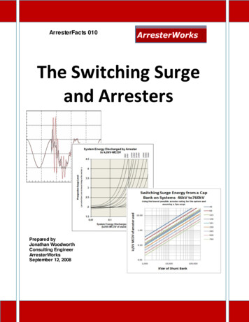
HWA Surge Protective Device (SPD)OperationOperationDANGERHAZARD OF ELECTRIC SHOCK, EXPLOSION, OR ARC FLASH Apply appropriate personal protective equipment (PPE) and follow safeelectrical work practices. See NFPA 70E. This equipment must only be installed and serviced by qualifiedelectrical personnel. Turn off all power supplying this equipment before working on or insideequipment. Always use a properly rated voltage sensing device to confirm power is off. Replace all devices, doors and covers before turning on power to thisequipment. This equipment must be effectively grounded per all applicable codes.Use an equipment-grounding conductor to connect this equipment tothe power system ground.Failure to follow these instructions will result in death or serious injury.LED Status IndicatorsDiagnostic LEDs are located on the front of the HWA SPD device. Theyoperate as follows: Verify that all phase voltages are present. If any of the LEDs are notilluminated, the device may not be installed correctly. Check the powersupply and service voltage. Upon energizing the SPD, check the LEDstatus. If all of the LEDs are illuminated, surge suppression is operating. If an inoperative condition occurs the device must be replaced byqualified electrical personnel.If one or more LEDs are not illuminated, there is a loss of surgesuppression on that phase.Figure 9:Diagnostic OperationIndicator Light ON OK8222-0012-07Indicator Light OFF Loss of surge suppression onthat phase and Audible AlarmON Loss of surge suppressionAudible AlarmThe audible alarm does not have a silence switch. Silence the alarm byremoving power from the SPD (open the circuit breaker that it is connectedto). The alarm indicates that the device needs replacement by qualifiedelectrical personnel. 2002–2016 Schneider Electric USA, Inc. All Rights ReservedFor troubleshooting, call the Surgelogic Technical Assistance Group at 1-800-577-7353.13ENGLISHRev. 01, 8222-001207/2016
HWA Surge Protective Device (SPD)OperationDry ContactsRev. 01, 8222-001207/2016ENGLISHThe HWA series SPD device is provided with dry contacts. The connectionfor the dry contacts is provided by twenty-four inch (61 cm) wire leads. Thewire leads are 22 AWG stranded copper wire. See Table 4 for wire colorand contact state. The unpowered state shall be closed between the redwire (common) and the yellow wire (normally closed). This is also the alarmcondition. The opposite state, closed between the red wire (common) andthe blue wire (normally open), indicates that power is on to the unit and thatno alarm condition exists (See Table 4). These dry contact leads can beused for remote indication of the SPD operating status to a computerinterface board or emergency management system. Also, these dry contactleads are designed to work with the SPD remote monitor option described inthe following section.The dry contacts are designed for a maximum voltage of 24 V dc / 24 V acand a maximum current of 2 A. Higher energy applications may requireadditional relay implementation outside the SPD. Damage to the SPD’srelay caused by use with energy levels in excess of those discussed in thisinstruction bulletin are not covered by warranty. For application questions,call the Surgelogic Technical Assistance Group at (800) 577-7353.Table 4:14Dry Contact ConfigurationDry ContactTerminalWire ColorPower off or Alarm Power on and noConditionAlarm ConditionN/O(Normally ally ClosedYellowClosedOpen 2002–2016 Schneider Electric USA, Inc. All Rights ReservedFor troubleshooting, call the Surgelogic Technical Assistance Group at 1-800-577-7353.
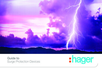
Remote Monitor OptionHWA Surge Protective Device (SPD)OperationThe remote monitor option has two LEDs, one red and one green, and anaudible alarm with an enable/disable switch. Normal status is a lit greenLED, and no audible alarm. To test the integrity of the remote monitor, pressthe push-to-test switch. The green LED will turn off, the red LED will turn on,and the alarm will sound, if the alarm is enabled. Releasing the switch willcomplete the test; the red LED will turn off, the green LED will turn on andthe alarm will shut off.If suppression on any phase is lost, the green LED will turn off, the red LEDwill illuminate and an alarm will sound. The audible alarm can be silenced bypushing the alarm enable/disable/test switch. The alarm will silence and thegreen alarm LED will not be lit. The red LED will continue to be illuminateduntil the inoperative condition has been cleared.The remote monitor includes a 120 V ac to 12 V dc adapter with a six-footpower cord. Connections are made to the HWA SPD diagnostic panel withthe twenty-four inch (61 cm) dry contact leads (provided). To extend theremote monitor further (up to 1,000 ft. (305 m)), use an additional length ofsolid or stranded 22 to 14 AWG wire (not provided).Figure 10:Remote Monitor Option 0(88.9)0.460(5.86)1.25 2.500(31.8) (63.5)2x Ø 0.187(4.75) OK Fault / Falla / DéfautMonitor Remoto / Moniteur À DistanceBouton pousser pour vérifierwww.SquareD.com 8220-0037A Made in USA / Hecho en E.U.A. / Fabriqué aux É.-U.Dry Contacts120 V power cord0.130(3.3)in.(mm)1.125(28.58) 2002–2016 Schneider Electric USA, Inc. All Rights ReservedFor troubleshooting, call the Surgelogic Technical Assistance Group at 1-800-577-7353.15ENGLISHRev. 01, 8222-001207/2016
HWA Surge Protective Device (SPD)Instruction BulletinPreventive MaintenanceRev. 01, 8222-001207/2016ENGLISHDANGERHAZARD OF ELECTRIC SHOCK, EXPLOSION, OR ARC FLASH Apply appropriate personal protective equipment (PPE) and follow safeelectrical work practices. See NFPA 70E. This equipment must only be installed and serviced by qualifiedelectrical personnel. Turn off all power supplying this equipment before working on or insideequipment. Always use a properly rated voltage sensing device to confirm power is off. Replace all devices, doors and covers before turning on power to thisequipment. This equipment must be effectively grounded per all applicable codes.Use an equipment-grounding conductor to connect this equipment tothe power system ground.Failure to follow these instructions will result in death or serious injury.Inspect the SPD periodically to maintain reliable system performance andcontinued transient voltage surge suppression. During this ins
Apply appropriate personal protective equipment (PPE) and follow safe electrical work practices. See NFPA 70E. This equipment must only be installed and serviced by qualified el