Transcription
Bucket Elevator1145 5th Ave SEHutchinson, MNBUCKET ELEVATOR v2p. 320-587-5505sales@warriormfgllc.comFebruary 19, 2019www.warriormfgllc.com1
This page left intentionally blank.BUCKET ELEVATOR v2February 19, 20192
Table of ContentsI.General. 5Introduction . 5 Equipment Identification . 5Safety . 6 General Safety Statement. 6 Decals . 7Receiving Inspection . 11II.Installation. 12General Assembly . 12 Typical Assembly/Installation Guidelines .12 General Arrangement Drawing .15 Boot Installation.16 Inspection Section Installation .18 Leg Section Installation, Standard and PressureRelief Vent Sections .18 Head and Hood Installation .20 Platforms and Optional Equipment.22Motor/Drives. 22Belt and Bucket Installation . 24Throat Wiper Adjustment. 26Common Platform Components. 27Common Platform Components (continued) . 28III.Initial Startup, Operation andAdjustment . 29Pre-Startup Inspection & Checklist . 29 Initial Belt Tension .29 Startup Preparation .31 Bucket Elevator Startup Checklist .32BUCKET ELEVATOR v2February 19, 20193
Startup and Tracking . 33 Startup .33 Head Pulley Tracking .33 Boot Pulley Tracking and Take-up Adjustment .34 Final Belt Tensioning.34IV.Troubleshooting . 36V.Maintenance . 40General Maintenance and Routine Inspection . 40VI.Warranty Statement . 42BUCKET ELEVATOR v2February 19, 20194
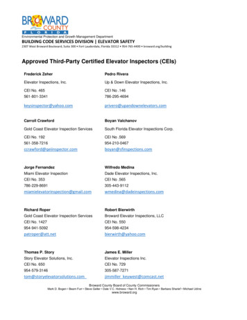
GeneralIntroductionThis manual is intended to provide basic information regarding the generaldesign features and installation of Warrior Mfg. Bucket Elevators. BecauseWarrior Mfg. offers many sizes, options and features, not all can be covered here.Refer to your particular general arrangement drawing for more specifics. Thismanual contains some general installation guidelines to consider. There aremany contractors that install bucket elevators and many have differing methodsand equipment available for installing the equipment. It is recommended areputable and experienced contractor be considered to install this equipment.This equipment cannot be expected to perform well if it is not installed well.Equipment IdentificationModel numbers consist of pulley diameter and trunk casing width:BE 30 20BE ------------ Bucket Elevator model24, 30, 36, 42, 48 --- Pulley diameter20, 26, 32, etc. -- Trunk casing widthThe equipment will have an ID tag with the order number located on the boot.The order number will be needed when making any inquiries regarding theequipment such as troubleshooting or ordering parts. Record information belowfor future reference.Order #:Date of Purchase:Notes:BUCKET ELEVATOR v2Figure 1: Typical ID tag locationFebruary 19, 20195
SafetyGeneral Safety StatementSafety is everyone’s responsibility. Construction sites and facilities where thisequipment is being installed and operated have constantly changing conditionsand hazards. Be alert and focused at all times. Identify and communicate safetyhazards with workers and determine appropriate safety precautions to be taken.Follow appropriate local and federal laws and safety regulations.During installation of this equipment, the installer will be lifting and handling avariety of different items that will be heavy, awkward and many timesunbalanced. The installer should be experienced in proper lifting and riggingtechniques and have the proper equipment to safely lift and install thisequipment to prevent injuries and damage to equipment. It is the installer’sresponsibility to install the equipment in accordance with established industrypractices, local codes and applicable regulations. It is also recommended toconsult with civil and structural engineers for seismic, soil & foundation andguying/bracing and other related requirements. Qualified and licensedelectricians must be used for the electrical wiring and servicing of the equipmentto ensure adequate power is supplied to the equipment.Do not modify the equipment without first contacting and getting approval fromWarrior Mfg. Some modifications could create hazardous conditions causingequipment damage and/or injury, and may void the equipment warranty.Operate the equipment in the manner and within the capacity in which it wasintended. Misuse can cause equipment damage, severe injury, or death. Followall lockout and other applicable safety rules when doing any maintenance andmaking adjustments.BUCKET ELEVATOR v2February 19, 20196
DecalsThe equipment has been supplied with safety labels warning individuals ofpotential hazards associated with operation and maintenance of the equipment.Ensure these labels remain legible at all times. Replacement labels areavailable at no charge from Warrior Mfg.BUCKET ELEVATOR v2February 19, 20197
DecalNumberDescription40029,40030Warrior ts40034WarningMoving PartsBUCKET ELEVATOR v2ImageFebruary 19, 20198
40035WarningRotating Parts40036WarningFlyingMaterial40037Warning LockOutBUCKET ELEVATOR v2February 19, 20199
40032 – Danger explosion40037 – Lock out40030 – Warrior logo40034 – Moving parts40033 – Exposed buckets40036 – Flying material40033 – Exposed buckets40035 – Flying rotating parts40035 – Flying rotating parts40037 – Lock out40032 – Danger explosion40033 – Exposed buckets40036 – Flying material40029 – Warrior logo40034 – Moving parts40035 – Rotating parts40036 – Flying material40036 – Flying materialFigure 2: Typical decal locationsBUCKET ELEVATOR v2February 19, 201910
Receiving InspectionInspect all equipment on each shipment immediately when unloading for anysigns of shipment damage or missing items. It is the responsibility of thereceiving party to note any damages/shortages on the freight bill before you signfor the shipment and then file claim with the carrier. The carrier is responsiblefor any shipping damages once the shipment leaves Warrior Mfg.All equipment, including hardware, is to be inventoried by the contractor within48 hours of receiving the shipment. Any shortages must be reported to WarriorMfg. within that initial 48-hour period. If shortages are discovered and reportedafter 48 hours, it is at Warrior’s discretion to charge the contractor for anyand/or all of the replacement parts and hardware needed.In many cases the equipment will arrive on multiple shipments, sosegregation/organization of equipment and paperwork at the site will minimizeconfusion and misplaced items.BUCKET ELEVATOR v2February 19, 201911
InstallationGeneral AssemblyTypical Assembly/Installation GuidelinesHow well the equipment is installed can have a huge impact on the overallperformance and operation of the equipment. The elevator MUST be plumbwithin ½” or less in both directions and the head and boot pulleys must bealigned with each other or belt tracking and rubbing issues will be problematic.It is recommended that all joints between sections be caulked during installationto provide a water- and dust-proof connection.WARNINGThe Bucket Elevator must be laterally supported every 20 ft from the headdown to the boot. Attach only to the trunking flanges. Do NOT attach to thetrunking sheet metal!BUCKET ELEVATOR v2February 19, 201912
Warrior bucket elevators are designed to be self-supporting vertically butrequire lateral support to brace horizontally. Laterally support the leg sectionsevery 20’ during installation to the base of the head section. This is typicallyaccomplished with horizontal supports from silos or tower structures. Optionalbolt-on tower connecting plates are available for connecting lateral supports tothe trunking flanges. The bucket elevator is not designed to support otherequipment such as distributors, spouting, etc. These items must be supported byseparate support structures.Figure 3: Trunking joint with tie angles and support brackets.It is recommended the installer consult with civil and/or structural engineersregarding foundations and support methods to ensure the installation isstructurally sound and does not affect the mechanical operation of theequipment. Warrior does not recommend guy cables for lateral support.Qualified and licensed electricians must be utilized to ensure adequate electricalsupply to the equipment. Refer to the general arrangement drawing for themotor requirements.BUCKET ELEVATOR v2February 19, 201913
In many cases, the discharge spouting and inlet transitions are field designedand fabricated. Careful consideration needs to be given to the flow of materialinto the boot of the elevator. Material needs to enter as straight into the boot aspossible to ensure proper cup fill and to prevent belt tracking issues. Bafflesmay be necessary to correct side loading issues.Figure 4: Typical minimum inlet hopper heights compared to boot pulley take-up upper limit.BUCKET ELEVATOR v2February 19, 201914
General Arrangement DrawingRefer to the general arrangement drawing for each specific bucket elevator.Each bucket elevator is unique based on many variables and options includingbut not limited to, size, height, capacity and other options. Some installationsrequire heavier gauge trunking to support the weight of the elevator. In somecases, the leg sections may have added reinforcement. These sections would belocated closest to the boot as shown on the general arrangement drawing alongwith other pertinent information. Reinforced sections are also used to supportplatforms and jib booms.HoodassemblyHeadassemblyUp sideDown sideStandardtrunkingsectionsRelief ventsectionsTie anglesInspectionsectionBoot assemblyFigure 5: Sample bucket elevator arrangement.Refer to your As Approved general arrangement drawing for correct stacking of trunkingBUCKET ELEVATOR v2February 19, 201915
Boot InstallationInstall the boot in the predetermined location on a suitable foundation. Levelthe top of the boot in both directions where the first leg section will sit. It isrecommended the boot be shimmed under the bottom as needed to level the topof the boot and anchor in place. Next, grout under the boot around the entireperimeter.The boot has stiffeners bolted around the top perimeter to maintain straightnessof the boot sides. These are to remain in place when installing the first trunksections.Figure 6: Typical boot components.BUCKET ELEVATOR v2February 19, 201916
Gravity Take-Up InstallationBolt upper gravity take-up brackets to provided reinforced trunking section.Bolt lower gravity take-up brackets to the sides of bearing take-up plate. Afterbelt installation (see page 30), disconnect and remove the standard acme take-uprods from the boot take-up plates. Once installation is complete, replace allprovided guarding to ensure safe operation.Figure 7: Gravity take-up installation & adjustment pointsBUCKET ELEVATOR v2February 19, 201917
Inspection Section InstallationThe inspection section is typically the first section to be installed above the boot,or the lowest, most convenient location above a pit or at a platform. Be sure theinspection door is located on the upside and towards the outside of the casing ofthe bucket elevator to provide an inspection opening for viewing bucket fill andgeneral bucket inspection. The belt and buckets can also be installed throughthe removable panels and the belt spliced at this location. Inspection panelsmay be flipped or swapped to put the inspection door at the best height forservice.Figure 8: Varying heights of inspection section doorLeg Section Installation, Standard and Pressure Relief Vent SectionsContinue installing leg sections above the inspection section while ensuring theyare straight, plumb and not twisted. Refer to the general arrangement drawingfor specific leg section locations. Pressure relief vent sections, if included, aretypically installed every other section vertically spacing the vents at 20’intervals. The pressure relief vents will typically be located at the top of each 10’leg section and are always designed to have the hinge at the bottom of each ventpanel. The vent panel will swing downward in the event of a deflagration eventto relieve pressure.BUCKET ELEVATOR v2February 19, 201918
WARNINGPay particular attention to orientation of leg sections. Some installationsrequire heavier gage sheet metal trunking and/or additionally reinforcedsections. These will typically be installed toward the bottom closest to theboot. Reinforced sections are also used to support platforms & jib booms.Refer to general arrangement drawings for locations.Tie angles connect between leg sections and are typically bolted on top of the legflanges. Special tie angles are used to connect ladder supports at predeterminedlocations. Refer to general arrangement drawing for details.3/8”-16 Grade 5 bolts are supplied to connect trunking sections to one another.All bolts are long enough to have at least 2 exposed threads (about 1/8”) past thenut through tie angles and supports. If thicker structural ties are used forlateral support of the elevator, longer bolts than those supplied may be required.3/8”-16Grade 5 boltsFigure 9: Typical trunking joint and tie angle installationBUCKET ELEVATOR v2February 19, 201919
Head and Hood InstallationThe head section is normally assembled at the factory with the shaft, bearingsand pulley installed. The head has lifting points located in the upper flangesthat can be utilized to hoist the section into position. Once in place, ensureadequate support/bracing is utilized to laterally support the head and dynamicforces imposed by the drive, wind and other attached devices.Figure 10: Typical head assembly lift points.WARNINGWhen rigging to the hood assembly, lift ONLY the hood. It cannot support theweight of the head section. The head section must be lifted separately.The hood assembly is shipped separate and is normally installed after the beltand buckets have been installed. When installing the hood onto the headassembly, caulk between the hood flange and mating surface of the head toprovide a water- and dust-proof connection.BUCKET ELEVATOR v2February 19, 201920
Ensure the entire installation is vertical and plumb within ½” left-to-right andfront-to-back. Check the head shaft to ensure it is perfectly level. The headshaft must be level or belt tracking will be problematic. If necessary, the headshaft can be leveled by adjusting shims located under the head bearings.Warrior Mfg. elevators come with shims installed under the head bearings tosimplify the leveling process. Determine which side of the shaft needs to belowered in order to achieve level. Loosen the bearing housing bolts and utilizethe jack bolt(s) under the bearing to lift weight off the bearing shim(s). Removeappropriate number of shims then back out the jack bolt(s) to lower the bearing.Figure 11: Head bearing adjustment points.Repeat process until level, tighten bearing housing bolts, and replace bearingguards.Figure 12: Typical head bearing guard installation.BUCKET ELEVATOR v2February 19, 201921
Platforms and Optional EquipmentIf optional platforms or jib booms are being supplied as part of the order, refer tothe appropriate general arrangement drawing for assembly details.Refer to the manufacturer’s instructions on other optional equipment such asrub blocks, bearing sensors, speed sensors, etc. for installation, operation andmaintenance of those items.Motor/DrivesRefer to the general arrangement drawing to ensure the proper motor, reducerand drive package components are being installed on the equipment. Ifinstalling a backstop, manually rotate reducer to ensure the backstop is installedthe correct direction to prevent damage on startup. Once reducer and backstopare installed, ensure reducer is filled with oil.Refer to the manufacturer’s instructions on motors, reducers and drivecomponents for proper installation, operation and maintenance intervals.NOTICEReducers are shipped without oil. Once installed, ensure reducer is filled tothe proper level with oil.Before installing the drive belts, jog the motor to check for proper rotation toprevent damage to the backstop and other components.Belt guards and mounting brackets are universal in nature to allowadjustability. When mounting, be sure motor and reducer shafts do not rub.Ensure the drive sheaves are aligned for maximum belt life and that they don’trub on belt guard.BUCKET ELEVATOR v2February 19, 201922
Figure 13: Typical drive belt and guard installation.Figure 14: Belt drive package components.Check tension on new drive belts frequently according to the manufacturer’sspecifications to prevent slippage and premature wear.BUCKET ELEVATOR v2February 19, 201923
Belt and Bucket InstallationSeveral methods of installing the belt and buckets may be utilized dependingupon size, width of belt, height of elevator, space available to work andequipment available. The removable panels on the inspection section are anideal location to feed the belt into the elevator, attach buckets and make thesplice. The buckets may be installed before installing the belt or afterwardsdepending on factors as mentioned above.Whichever method is used, once the belt is installed, pre-stretching the belt priorto final splicing will require less adjustment and re-splicing during the break inperiod.When attaching buckets, the head of the elevator bolt should lie against the insidesurface of the elevator belt with the washers and nuts on the inside of the elevatorbucket. An ideal installation will result in the elevator bolt head fitting snugglyjust below the surface of the elevator belt. It is recommended that a pneumaticwrench or battery-operated drill-driver be used. The proper torque setting forinstalling elevator bolts is truly impossible to specify. Each assembly system willhave its own unknown coefficients of friction and properties of resistancedepending on the coating or other contaminates. Elevator belts vary in hardnessor softness which affects the torque required to get the head of the bolt to seatproperly.Figure 15: Standard hardware package and installation order.For fanged bolts, align the fangs in a horizontal line across the width of the belt.Sometimes it helps to “set” the fangs into the belt cover by tapping them with amallet. Once the bolt is tightened, the fangs will draw up into the belt so that thehead can properly seat. Fanged bolts may have trouble penetrating unusuallyhard belts like PVC450, especially in cold temperatures.BUCKET ELEVATOR v2February 19, 201924
Figure 16: Proper alignment of fanged bolts.Several splicing methods may be utilized including lap and mechanical splices.The method needs to be determined when ordering the belt to ensure adequatebelt length. Belt splices must be square or tracking problems will beencountered. If a lap splice is utilized, refer to the general arrangement drawingfor proper number of buckets overlap for the splice. Make sure the boot pulley isadjusted to the top of its take-up range prior to splicing the belt. Refer to Figure17 below for an example of a lap splice, or the manufacturer’s instructions forinstallation of mechanical splices.Figure 17: Example of 3-bucket lap belt splice.See the As Approved drawing for each order for the actual splice type required.BUCKET ELEVATOR v2February 19, 201925
Throat Wiper AdjustmentOnce the belt and buckets have been installed, the throat wiper located in thedischarge throat of the head must be adjusted to within 1/8” to 1/4" from the lipof the buckets. If a lap or butt splice is used, be sure to adjust the throat wiperto accommodate for one belt thickness at the splice area. Loosen the throatwiper retaining bolts, slide the throat wiper to get proper clearance andretighten the bolts.Figure 18: Throat wiper to bucket tip adjustment in head assembly.BUCKET ELEVATOR v2February 19, 201926
Common Platform ComponentsBUCKET ELEVATOR v2February 19, 201927
Common Platform Components (continued)BUCKET ELEVATOR v2February 19, 201928
Initial Startup, Operation and AdjustmentPre-Startup Inspection & ChecklistInitial Belt TensionInitial belt tension can be accomplished by loosening the nuts on the boot takeup adjusting screws allowing the boot pulley to slide down under its own weightand rest in the cradle of the belt. Adjust the take-up nuts that apply downwardpressure to the boot pulley until they begin applying downward pressure. Turnthe nuts an additional 1 – 2 turns. Check to ensure both sides are adjustedevenly. Final tensioning will be done under full load and is covered later in thismanual (see page 33) .Figure 19: Boot pulley take-up adjustment points.BUCKET ELEVATOR v2February 19, 201929
Gravity Take-UpTo ensure proper tension of belts with a gravity take-up, first use a liftingharness with forklift or come-along to check that the take-up travels up anddown freely along its range of movement. Remove the gravity take-up bin coverand place inside the required amount of counterweight. Warrior will provide inwriting the minimum amount of weight required for use, as well as maximumamount of weight that can be added and avoid failure. Replace the bin cover tokeep water and foreign material from adding unwanted weight to the take-up.Figure 20: Tracking & tension adjustment points on boots with gravity take-upBUCKET ELEVATOR v2February 19, 201930
Self-Cleaning Boot TensioningSelf-cleaning boots have a single acme screw on each side to adjust the bucketclearance as well as belt tension. Start by adjusting the bottom section of theacme screw, so the clearance from the outer-most bucket tips (including diggerbuckets or those on the extra thickness of a lap splice) to the curved bottom ofthe boot is within acceptable limits. Then adjust belt tension with the topsection of the acme screw using the standard method above. Loosen until thepulley rests under its own weight, then tighten until pressure is applied, plus anadditional 1 – 2 turns.Bucket clearanceadjustmentBelt tensionadjustmentFigure 21: Self-cleaning boot adjustment points.Startup PreparationAs stated above, make sure the motor rotation has been checked with the drivebelts removed to prevent damage to the backstop and other components.Ensure all tools, parts, and equipment are clear of the bucket elevator andworkers are safely located before initial startup. The checklist on the followingpage can be used as a reference for starting up the equipment for the first time.BUCKET ELEVATOR v2February 19, 201931
Warrior MfgBucket Elevator Startup ChecklistPRE-STARTUP INSTALLATION INSPECTIONVerify boot hopper location and check for possible side loading issues.Ensure leg sections are straight and plumb.Ensure all joints are sealed with caulk.Ensure all hardware is installed and tight.Verify elevator is properly supported/braced.Review drive for proper installation and verify reducer filled with oil.Verify motor rotation. Remove drive belts to prevent any damage if reversed.Ensure backstop is installed correctly.Verify head and boot pulleys are centered, aligned, and plumb.Ensure belt is spliced correctly and splice is straight.Ensure bucket bolts are seated completely on backside of belt, and washers andnuts are used inside the plastic bucket.Ensure all platforms, ladders, etc. are securely mounted and fasteners are seatedand tight.Verify throat wiper below head pulley has been properly adjusted.Verify auxiliary equipment such as speed switches, rub blocks, etc. have beeninstalled and tested.Ensure boot pulley take-ups are adjusted for initial belt tension.INITIAL STARTUPPosition observers at the head and boot areas to observe belt tracking.Jog elevator and if tracking well, continue to run.Adjust boot pulley take-ups for belt tracking. Adjust head pulley shims as needed.Continue listening for any noises and inspect drive and drive belts.Verify head shaft RPM matches the general arrangement drawing.INITIAL OPERATIONBegin feeding product slowly while observing belt tracking and listen for anyunusual noises.Refer to general arrangement drawing for bucket fill level, material type and speedinformation.Observe belt tracking as material is added and adjust pulleys as necessary.Slowly increase flow to full capacity while observing for any issues.While running under full load, adjust boot take-ups for proper belt tension toprevent slippage on head pulley.Verify no feeding or discharge issues. Utilize strobe light for bucket fill if needed.Continue monitoring belt tension and belt tracking. Adjust as needed.BUCKET ELEVATOR v2February 19, 201932
Startup and TrackingStartupSafely position workers at head and boot areas to observe belt tracking on initialstartup. If there are initial tracking issues, the equipment should be stoppedimmediately to prevent damage. Also listen for any unusual noises and correctand/or make adjustments as needed.Head Pulley TrackingIf belt tracks to one side at the head, head bearing shims may need to beadjusted to correct tracking. Remove shim(s) and lower head shaft on oppositeside belt tracks towards. The belt will begin to track towards the side beinglowered. Refer to head installation section of manual above for more detail.If belt tracks to thisside, remove shimsfrom the OPPOSITEside to adjust it DOWNIf belt tracks to thisside, remove shimsfrom the OPPOSITEside to adjust it DOWNFigure 22: Correction of belt tracking at head.Other causes of head pulley misalignment include loose bearings, a bent headshaft, or pulley movement along the shaft due to loose bushings.BUCKET ELEVATOR v2February 19, 201933
Boot Pulley Tracking and Take-up AdjustmentSmall adjustments may be needed at the boot pulley to get the belt tracking inthe middle of the pulley. If the belt tracks to one side, adjust the take-up on thatside downward to get the belt tracking in the middle. Be sure to recheck the belttracking at the head.If belt tracks to this side,adjust the acme screwIf belt tracks to this side,adjust the acme screwfor THIS bearing DOWNfor THIS bearing DOWNFigure 23: Correction of belt tracking at boot.Other causes of boot pulley misalignment include grain entering the inlet hopperat an angle, the head pulley out of plumb, or pulley movement along the shaftdue to loose bushings.Final Belt TensioningBelt tension must be sufficient to prevent slippage on the head pulley under fullload. If belt is allowed to slip for a significant period of time, the head laggingmay become glazed and greater belt pressure will be required for proper tractionon the belt. Severe cases will result in belt damage. Once the belt begins to slip,the buckets will begin to overfill, adding to the weight being elevated andcompounding the problem. This can also be a cause of the elevator not achievingcapacity.Once the elevator has been operated empty and belt is tracking well at bothhead and boot, begin slowly feeding material into the elevator while observingtracking at the head and boot. Continue increasing material until full capacityis reached. At the same time, slowly loosen the take-up nuts on both sides of theBUCKET ELEVATOR v2February 19, 201934
boot and allow the boot pulley to go down and rest in the cradle of t
BUCKET ELEVATOR v2 February 19, 2019 1 Bucket Elevator 1145 5th Ave SE Hutchinson, MN p. 320-587-5505 sales@warriormfgllc.com www.warriormfgllc.com