Transcription
User GuideAudio SpeakersSF 3PTPendant Speakers68-3094-01 Rev. C05 19
Safety InstructionsSafety Instructions EnglishWARNING: This symbol,, when used on the product, is intended toalert the user of the presence of uninsulated dangerous voltage within theproduct’s enclosure that may present a risk of electric shock.ATTENTION: This symbol,, when used on the product, is intendedto alert the user of important operating and maintenance (servicing)instructions in the literature provided with the equipment.For information on safety guidelines, regulatory compliances, EMI/EMFcompatibility, accessibility, and related topics, see the Extron Safety andRegulatory Compliance Guide, part number 68-290-01, on the Extronwebsite, www.extron.com.Sicherheitsanweisungen DeutschWARNUNG: Dieses Symbolauf dem Produkt soll den Benutzer daraufaufmerksam machen, dass im Inneren des Gehäuses dieses Produktesgefährliche Spannungen herrschen, die nicht isoliert sind und die einenelektrischen Schlag verursachen können.VORSICHT: Dieses Symbolauf dem Produkt soll dem Benutzer inder im Lieferumfang enthaltenen Dokumentation besonders wichtigeHinweise zur Bedienung und Wartung (Instandhaltung) geben.Weitere Informationen über die Sicherheitsrichtlinien, Produkthandhabung,EMI/EMF-Kompatibilität, Zugänglichkeit und verwandte Themen finden Sie inden Extron-Richtlinien für Sicherheit und Handhabung (Artikelnummer68-290-01) auf der Extron-Website, www.extron.com.Instrucciones de seguridad EspañolADVERTENCIA: Este símbolo,, cuando se utiliza en el producto,avisa al usuario de la presencia de voltaje peligroso sin aislar dentro delproducto, lo que puede representar un riesgo de descarga eléctrica.ATENCIÓN: Este símbolo,, cuando se utiliza en el producto, avisaal usuario de la presencia de importantes instrucciones de uso ymantenimiento recogidas en la documentación proporcionada con elequipo.Para obtener información sobre directrices de seguridad, cumplimientode normativas, compatibilidad electromagnética, accesibilidad y temasrelacionados, consulte la Guía de cumplimiento de normativas y seguridadde Extron, referencia 68-290-01, en el sitio Web de Extron, www.extron.com.Instructions de sécurité FrançaisAVERTISSEMENT :Ce pictogramme,, lorsqu’il est utilisé sur leproduit, signale à l’utilisateur la présence à l’intérieur du boîtier duproduit d’une tension électrique dangereuse susceptible de provoquerun choc électrique.ATTENTION : Ce pictogramme,, lorsqu’il est utilisé sur le produit,signale à l’utilisateur des instructions d’utilisation ou de maintenanceimportantes qui se trouvent dans la documentation fournie avec lematériel.Pour en savoir plus sur les règles de sécurité, la conformité à laréglementation, la compatibilité EMI/EMF, l’accessibilité, et autres sujetsconnexes, lisez les informations de sécurité et de conformité Extron, réf.68‑290-01, sur le site Extron, www.extron.com.Istruzioni di sicurezza ItalianoAVVERTENZA:Il simbolo,, se usato sul prodotto, serve adavvertire l’utente della presenza di tensione non isolata pericolosaall’interno del contenitore del prodotto che può costituire un rischio discosse elettriche.ATTENTZIONE: Il simbolo,, se usato sul prodotto, serve ad avvertirel’utente della presenza di importanti istruzioni di funzionamento emanutenzione nella documentazione fornita con l’apparecchio.Per informazioni su parametri di sicurezza, conformità alle normative,compatibilità EMI/EMF, accessibilità e argomenti simili, fare riferimentoalla Guida alla conformità normativa e di sicurezza di Extron, cod. articolo68‑290‑01, sul sito web di Extron, www.extron.com.Instrukcje bezpieczeństwa PolskaOSTRZEŻENIE: Ten symbol,, gdy używany na produkt, ma na celupoinformować użytkownika o obecności izolowanego i niebezpiecznegonapięcia wewnątrz obudowy produktu, który może stanowić zagrożenieporażenia prądem elektrycznym.UWAGI: Ten symbol,, gdy używany na produkt, jest przeznaczony doostrzegania użytkownika ważne operacyjne oraz instrukcje konserwacji(obsługi) w literaturze, wyposażone w sprzęt.Informacji na temat wytycznych w sprawie bezpieczeństwa, regulacjiwzajemnej zgodności, zgodność EMI/EMF, dostępności i Tematy pokrewne,zobacz Extron bezpieczeństwa i regulacyjnego zgodności przewodnik, częśćnumer 68-290-01, na stronie internetowej Extron, www.extron.com.Инструкция по технике безопасности РусскийПРЕДУПРЕЖДЕНИЕ:Д анный си м в ол, , если ук азанна прод ук те, пред упреж д ает поль зов ателя о нали чиинеи золи ров анного опасного напряж ени я в нутри к орпусапрод ук та, к оторое м ож ет при в ести к пораж ени юэлек три ческ и м ток ом .ВНИМАНИЕ: Д анный си м в ол, , если ук азан на прод ук те,пред упреж д ает поль зов ателя о нали чи и в аж ных и нструк ци йпо эк сплуатаци и и об служ и в ани ю в рук ов од ств е,при лагаем ом к д анном у об оруд ов ани ю .Д ля получени я и нф орм аци и о прав и лах техни к и б езопасности ,соб лю д ени и норм ати в ных треб ов ани й , элек тром агни тнойсов м ести м ости (Э М П/ Э Д С), в озм ож ности д оступа и д руги хв опросах см . рук ов од ств о по б езопасности и соб лю д ени юнорм ати в ных треб ов ани й E xtron на сай те E xtron: ,www.extron.com, ном ер по к аталогу - 68 -29 0-01 .安全说明 �警告用户该产品机壳内有暴露的危险 电压,有触电危险。注 意:产 品 上 的 这个 标 志 意 在 提 示 用 户 设 备 随 附 的 用 户 手 册 中 EMI/EMF �容,敬请访问 Extron 网站 , www.extron.com,参见Extron 安全规范指南,产品编号 68-290-01。
安全記事 繁體中文안전 지침 한국어警 告:若產品上使 用此 符 號 ,是 為了提 醒 使 用者,產品 機 殼內存 在 EMF �訊,請瀏覽 Extron 網站:www.extron.com,然後參閱《Extron 安全性與法規遵守手冊》,準則編號 68-290-01。경고: 이 기호가 제품에 사용될 경우, 제품의 인클로저 내에 있는접지되지 않은 위험한 전류로 인해 사용자가 감전될 위험이 있음을경고합니다.주의:이 기호가 제품에 사용될 경우, 장비와 함께 제공된 책자에 나와있는 주요 운영 및 유지보수(정비) 지침을 경고합니다.안전 가이드라인, 규제 준수, EMI/EMF 호환성, 접근성, 그리고 관련 항목에대한 자세한 내용은 Extron 웹 사이트(www.extron.com)의 Extron 안전 및규제 준수 안내서, 68-290-01 조항을 참조하십시오.安全上のご注意 日本語警告: 示しています。注意: � www.extron.com より『Extron Safetyand Regulatory Compliance Guide』(P/N 68-290-01) をご覧ください。Copyright 2019 Extron Electronics. All rights reserved. www.extron.comTrademarksAll trademarks mentioned in this guide are the properties of their respective owners.The following registered trademarks ( ), registered service marks (SM), and trademarks (TM) are the property of RGB Systems, Inc. orExtron Electronics (see the current list of trademarks on the Terms of Use page at www.extron.com):Registered Trademarks ( )Extron, Cable Cubby, ControlScript, CrossPoint, DTP, eBUS, EDID Manager, EDID Minder, Flat Field, FlexOS, Glitch Free. GlobalConfigurator, Global Scripter, GlobalViewer, Hideaway, HyperLane, IP Intercom, IP Link, Key Minder, LinkLicense, LockIt, MediaLink,MediaPort, NetPA, PlenumVault, PoleVault, PowerCage, PURE3, Quantum, Show Me, SoundField, SpeedMount, SpeedSwitch,StudioStation, System INTEGRATOR, TeamWork, TouchLink, V‑Lock, VideoLounge, VN‑Matrix, VoiceLift, WallVault, WindoWall, XTP,XTP Systems, and ZipClipRegistered Service Mark(SM) : S3 Service Support SolutionsTrademarks ( )AAP, AFL (Accu‑Rate Frame Lock), ADSP (Advanced Digital Sync Processing), Auto‑Image, AVEdge, CableCover, CDRS (Class DRipple Suppression), Codec Connect, DDSP (Digital Display Sync Processing), DMI (Dynamic Motion Interpolation), Driver Configurator,DSP Configurator, DSVP (Digital Sync Validation Processing), eLink, EQIP, Everlast, FastBite, FOX, FOXBOX, IP Intercom HelpDesk,MAAP, MicroDigital, Opti‑Torque, PendantConnect, ProDSP, QS‑FPC (QuickSwitch Front Panel Controller), Room Agent, Scope‑Trigger,ShareLink, SIS, Simple Instruction Set, Skew‑Free, SpeedNav, Triple‑Action Switching, True4K, Vector 4K , WebShare, XTRA, andZipCaddy
Conventions Used in this GuideNotificationsThe following notifications are used in this guide:WARNING: Potential risk of severe injury or death.AVERTISSEMENT :Risque potentiel de blessure grave ou de mort.CAUTION: Risk of minor personal injury.ATTENTION : Risque de blessure mineure.ATTENTION: Risk of property damage. Risque de dommages matériels.NOTE: A note draws attention to important information.Specifications AvailabilityProduct specifications are available on the Extron website, www.extron.com.Extron Glossary of TermsA glossary of terms is available at http://www.extron.com/technology/glossary.aspx.
ContentsOverview. 1Features. 1SF 3PT Application Examples. 2Installation. 4Installing the SF 3PT Speaker. 5Wiring the SF 3PT Speaker Assembly. 6Wiring the SF 3PT Ceiling Bracket. 11Completing the SF 3PT Installation.Reference Information. 15Measuring and Pre-Cutting thePendantConnect Speaker Cable. 16Painting the Speaker Grille. 17Painting the Speaker Enclosure. 18SF 3PT User Guide Contentsv
NetPA AT Series User Guide Contentsvi
IntroductionThis section gives an overview of the Extron SF 3PT pendant speaker. Topics include: About this Guide Overview Features SF 3PT Application ExamplesAbout this GuideThis guide describes the installation and set up of the SF 3PT pendant speaker.OverviewThe Extron SF 3PT speaker is a pendant speaker suspended by a cable that incorporatesa steel cable and the speaker wiring. The SF 3PT is ideal for open and mixed ceilingapplications.Features 3” (76 mm) full-range driver — Designed for speech reinforcement and musicplayback Frequency range — 110 Hz to 20 kHz 8 ohm direct or 70/100 volt operation — 8 ohm direct 70 volt: 16, 8, 4, 2, and 1 watt selectable 100 volt: 16, 8, 4, and 2 watt selectable 116 conical dispersion 16 watts continuous pink noise32 watts continuous program Architecturally clean, patent pending design using Extron exclusivePendantConnect speaker cable — Blends in well with contemporary pendantlighting fixtures for an aesthetically pleasing appearance, includes a 20’ (6.1 m) length ofPendantConnect speaker cable per pair Similar voicing to the Extron SF 3CT LP and SF 3C LP ceiling speakers —Allows smooth sonic transitions when using SF 3PT and SF 3CT LP or SF 3C LPspeakers in mixed ceiling applications Available in black or white and is paintable to fit in with any décor UL 1480A listed for safetySF 3PT User Guide Introduction1
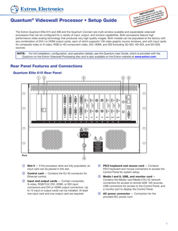
Optional 20 foot (6.1 m) length of PendantConnect speaker cable — Black WhiteOptional 500 foot (152 m) spool of PendantConnect speaker cable — Black White5-year parts and labor warranty NOTE: This speaker is intended for indoor dry environment only.SF 3PT Application ExamplesThe following illustrations are two examples of configuring the SF 3PT speakers.ExtronSF 480p720p 1080i 1080pDIRECTVHDSELECTDIRECTVSatellite Receiver1234567890PUSHTUNINGPUSHPOWERStereo Media 20p 1080i 1080pDIRECTVIRAudioRS-232CATV TunerHDMIHDMIHDSELECTDIRECTVPUSH ENTERPOWERONOFFAUX INTUNINGStereo BGMCATV TunerSatellite ReceiverIRCAT5 CableHDMIRS-232AudioCAT5 CableCAT5 CableCOMINPUTS12 3 4 512 3 4eBUS6 7S8PoE SwitchExtronTLP Pro EWI/OESCVIDEO123MIC VOLUME2VOLUMEAUDIODTP CROSSPOINT 84 SERIESDIGITAL PRESENTATION MATRIXAudio10" TouchLinkPro TouchpanelLIMITOVERCONTROLCONFIGOUTPUTSCATxPaging SystemExtronDTP HDMI 4K 230 RxExtronDTP CrossPoint 844K IPCP MA 704K Scaling PresentationMatrix SwitcherCATxOVER DTPRS-232OVER DTPIRTx Rx G Tx RxRS-232IRTx Rx G Tx RxDTP HDMI 230 RxDTP HDMI 230 RxReceiverReceiverHDMIRS-232MODEL 80RS-232HDMIMODEL 80FLAT PANELDisplayFigure 1.ExtronDTP HDMI 4K 230 RxFLAT PANELDisplayApplication Example: Background Music and PagingSF 3PT User Guide Introduction2
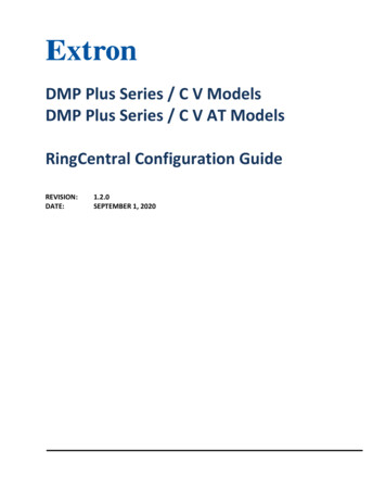
ExtronSF 3CT LPCeiling SpeakersExtronSF 3PTPendantSpeakersAudioAudio1Stereo Media Player2345SEARCH678STOP90TUNINGBACKPLAY/PAUSEPUSH ENTERPOWERONOFFAUX INTUNINGStereo ITER/PROTECTSIGNALXPA 1002DMP 128 PlusDIGITAL MATRIX PROCESSORExtronDMP 128 PlusDigital Matrix ProcessorAudioMUTEMICPROGRAMFigure 2.AmplifierACPVOLUMEPaging SystemExtronXPA 1002-70VExtronACP 106DAudio Control PanelApplication Example: Mixed Open/Drop-Ceiling EnvironmentSF 3PT User Guide Introduction3
InstallationThis section describes the installation of the SF 3PT speaker and includes the followingtopic:Installing the SF 3PT Speaker WARNING: Risk of personal injury or property damage. The final installationshould be able to continuously support the speaker weight. The final installationshould also be able to support any short term overloading. Since applications canvary considerably, it is assumed that the installer will exercise good judgment whenselecting the mounting location, method, and hardware. Installation and service mustbe performed by authorized personnel only.AVERTISSEMENT : Risque de dommages corporels ou matériels.L’installation finale doit pouvoir supporter en permanence le poids de l’enceinte.L’installation finale doit également supporter toute surcharge temporaire. Étant donnéla possibilité d’évolution considérable des applications, il est supposé que l’installateurfera preuve de discernement lors de la sélection de l’emplacement, du mode, etdu matériel de montage. L’installation et la maintenance du système doivent êtreexclusivement effectuées par le personnel autorisé.NOTE: This speaker is intended for flexible wiring connection only.SF 3PT User Guide Installation4
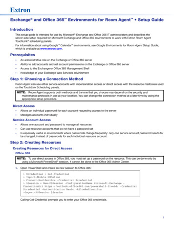
Installing the SF 3PT SpeakerThe SF 3PT speaker is ideal for open ceilings. It is suspended from a user-supplied“octagon” type ceiling electrical box, as shown below.“Octagon” Type Ceiling Electrical BoxCeiling BracketCeiling Bracket Cover PlatePendantConnect Speaker CableSpeaker CapSpeakerFigure 3.SF 3PT Speaker AssemblyNOTE: The octagon type ceiling electrical box is not included.SF 3PT User Guide Installation5
Wiring the SF 3PT Speaker AssemblyThe SF 3PT speaker assembly includes the SF 3PT speaker with a cap, a PendantConnectspeaker cable that incorporates both the speaker wires and a steel support cable, and aceiling bracket with a cover plate.Installation requires attaching the ceiling bracket to a suitable overhead “octagon” typeceiling electrical box hereafter noted as ceiling box (not included), as shown in the previousfigure. Follow the steps to properly install the speaker.NOTE: Make sure to consult and follow local electrical and building codes whenmounting the SF 3PT Ceiling Bracket to a ceiling box. The following points must betaken into account: The mounting screw hole pattern needs to be between 2.36" and 3.50" (60 mmand 89 mm). The ceiling electrical box that the SF 3PT is mounting to needs to be rated tosupport sufficient weight. The SF 3PT speaker weighs 3.6 lbs. (1.6 kg) with speaker cap, Ceiling Bracket/Cover Plate, and 10' (3.1 m) of PendantConnect cable.NOTES: To help determine the necessary length of PendantConnect speaker cable needed,if pre-cutting, refer to the Reference Information section, otherwise follow thesteps below. When using pre-cut cables as described in the Reference Information section,skip step 5.1. Locate a suitable mounting location for the SF 3PT.2. Install and wire a ceiling box where the ceiling bracket is to be attached.NOTE: The ceiling box must be attached to a permanent structural member ofthe building and be able to support the complete speaker assembly includingthe speaker and cap, cable, and the ceiling bracket and cover plate. See theWarning at the beginning of the “Installation” section.3. Lift the speaker cap from the back of the speaker to expose the cable connectionsSF 3PT User Guide Installation6
4. Insert the PendantConnect speaker cable through the compression fitting and outthrough the recessed cable guide. See 1 in the figure below. Route enough excesscable to allow you to easily work with the cable end.1Compression NutPendantConnectSpeaker CableCompressionFitting2Figure 4.Speaker WiringNOTE: Be sure that the compression nut (the large top nut) has been loosened, butnot removed.5. Strip the cable jacket. See the following Note.NOTE: When using pre-cut cables, as described in the Reference Informationsection, skip this step (step 5).Remove the outer protective cable jacket and filler material from 6 inches of cable thatwas pushed through the bottom of the compression fitting. See 2 in the illustrationabove.6. Pull the cable back up through the compression fitting until the end of the cable withthe jacket still intact just protrudes from the bottom of the compression fitting. See 1below. Then tighten the top compression nut so that the cable is secure. See 2 in thefigure below.Side View1CompressionFittingCompressionNut2Figure 5.Routing the Speaker CableNOTE: The compression nut is tight when the bottom of the compression nuttouches the compression fitting. Tighten to at least 30 in-lb (3.4 N m).SF 3PT User Guide Installation7
7. Using the guide on the side of the splicing connector, strip .43 inch (11 mm) from theends of the black and red wires coming from the cable. These wires will be inserted intothe 2-pole splicing connectors of the speaker.43" (11 mm)DO NOT TIN the wires.8. Lift the splicing connector lever 1 and insert the stripped end of the red wire intothe empty pole of the connector 2 that is attached to the red wire coming from thespeaker. Press the lever down to lock the red wire in place 3.132Figure 6.2-pole Splicing ConnectorNext, lift the connector lever 1 and insert the stripped end of the black wire into theempty pole of the connector 2 that is attached to the black wire coming from thespeaker. Press the lever down to lock the black wire in place 3.9. The speaker wires are now connected at the back of the speaker.2-Pole SplicingConnectorsFigure 7.Connected Speaker WiresSF 3PT User Guide Installation8
10. Secure the red and the black speaker wires coming from the cable to the tie-off pointusing the tie-wrap.Tie-OffPointTie-WrapFigure 8.Speaker Wires Tie-Off Point11. Route the steel cable from the bottom of the compression fitting 1 and through oneside of the steel cable guide in the speaker bracket.Steel CableAnchor Screw4321Figure 9.Steel CableSteel CableGuideAnchoring the Steel Cable to SpeakerNext, loosen the steel cable anchor screw 2 and pull the steel cable tightly under thecaptive washer of the screw 3, then tighten the screw 4. Pull the free end of the steelcable through the other cable guide in the bracket.NOTE: It is not required to remove the outer jacket from the steel cable.SF 3PT User Guide Installation9
12. Use a Tweeker or small screwdriver to set the tap selection switch to the desiredposition.Tap SelectionSwitch8Ω100 V8Ω8Ω16W8W4W2W1W70 V100V8Ω2W4W8W16W16W8W4W2W1W70 VFigure 10.2W4W8W16WTap Selection SwitchSF 3PT User Guide Installation10
Wiring the SF 3PT Ceiling Bracket6” (15.2 cm)CeilingBracketCeiling BracketCover PlatePendantConnectSpeaker CableASpeakerCapSpeakerBFigure 4.Order of AssemblyFloorNOTE: When using pre-cut cables, as described in the Reference Informationsection, skip steps 1, 3, and 4.1. Determine the proper cable length. Refer to the figure above at right.Measure the distance from the floor to the bottom of the ceiling box (value A) and alsofrom the floor to the bottom of the speaker at the planned hanging height (value B).Next, subtract value B from value A for an approximate measurement.See the Note above.2. Route the free end of the cable through the speaker cap so that the cap is facing thespeaker correctly.3. With the speaker cap in place, measure out the distance obtained in step 1 from the topof the speaker assembly and mark the cutting point.See the Note above.4. Cut and strip the other end of the cable using the steps below. See the Note above.a. Cut the cable at the point marked in step 3.ATTENTION: Do not use regular wire cutters to cut through the steel cable.Ordinary wire cutters may be damaged when attempting to cut through thesteel cable. You must use a suitable cable cutter to cut the steel cable.ATTENTION : N’utilisez pas de cisaille standard pour couper le câble en acier.Ce type de cisaille peut être endommagé lors de la coupe du câble en acier.Vous devez utiliser une pince coupe-câble adaptée à ce type de câble.SF 3PT User Guide Installation11
b. Measure and mark 6 inches (15.2 cm) from the end of the cable, 1. This is thepoint where the cable jacket will be stripped.1PendantConnectSpeaker Cable2Ceiling BracketFigure 5.6” (15.2 cm)CompressionNutCeiling Bracket Cablec. Remove the outer protective cable jacket and filler material at the mark you made.Cable Jacket(Removed)CompressionFittingCeiling BracketFigure 6.Cable Bracket Cable Stripping5. Next, route the free end of the cable through the ceiling bracket cover plate so that themagnetic cover plate is correctly facing the ceiling bracket to be installed.6. Route the free end of the cable through the bottom of the compression nut of the ceilingbracket.NOTE: Be sure that the compression nut (the large bottom nut) of the ceilingbracket has been loosened, but not removed.7. Pull the cable until the jacket just protrudes from the top of the compression fitting andtighten the compression nut (see 2 in step 4b above) to secure the cable.NOTE: The compression nut is tight when the bottom of the compression nut (flatpart) touches the compression fitting. Tighten to at least 30 in-lb (3.4 N m).8. Using the guide on the side of the splicing connector, strip .43 inch (11 mm) from theends of the protruding black and red wires. These wires will be inserted into the two3-pole splicing connectors (included).43" (11 mm)DO NOT TIN the wires.SF 3PT User Guide Installation12
9. Lift one lever of one 3-pole splicing connector 1 and insert the stripped end of the redwire into an empty pole of the connector 2. Press the lever down to lock the red wire inplace 3. See the figure below.312Figure 14.3-pole Splicing ConnectorNext, lift one lever of the other 3-pole splicing connector 1 and insert the stripped endof the black wire into an empty pole of the connector 2. Press the lever down to lockthe black wire in place 3.10. Route the steel cable from the top of the compression fitting and through one side ofthe steel cable guide 1 in the ceiling bracket, as shown below.3Steel CableAnchor Screw42SteelCable1Steel CableGuideSide ViewFigure 15.Anchoring the Steel Cable to Ceiling BracketNOTE: It is not required to remove the outer jacket from the steel cable.Next, loosen the steel cable anchor screw 2 and pull the steel cable tightly under thecaptive washer of the anchor screw, then tighten the screw 3. Pull the free end of thesteel cable through the other cable guide in the bracket 4.11. Place the speaker and cable assembly into the included bag and hang the bag close tothe ceiling box for the final installation steps.12. Remove the ceiling bracket from the bag and connect the speaker wires coming fromthe ceiling box to the 3-pole splicing connectors on the ceiling bracket. The red speakerwire coming from the ceiling box connects to the splicing connector wired to the redwire, and the black speaker wire coming from the ceiling box connects to the splicingconnector wired to the black wire.NOTE: Each pole of the splicing connector is capable of accepting up to 12 AWGwire.SF 3PT User Guide Installation13
Wire the 3-pole splicing connectors for a Loop-through configuration.Loop-through:Red Wire ( ) from Previous Speaker/AmplifierRed Wire ( ) to Next SpeakerRed Wire ( ) to SpeakerBlack Wire (-) from Previous Speaker/AmplifierBlack Wire (-) to Next SpeakerBlack Wire (-) to SpeakerFigure 16.Loop-through Configuration13. Using two screws, attach the ceiling bracket to the ceiling box with the splicingconnectors inserted into the ceiling box.Ceiling BoxCeiling BracketScrewCeiling BracketCover PlateFigure 17.Attaching Ceiling Bracket to Ceiling BoxSF 3PT User Guide Installation14
ReferenceInformationThis section describes the installation of the SF 3PT speaker and includes the followingtopics: Measuring and Pre-Cutting the PendantConnect Speaker Cable Painting the Speaker Grille Painting the Speaker EnclosureSF 3PT User Guide Reference Information15
Measuring and Pre-Cutting the PendantConnect Speaker CableTo determine the length of the PendantConnect speaker cable to cut, do the following.1. Refer to the illustrations below.a. Measure the distance from the floor to the bottom of the ceiling box (value A).b. Next, measure the distance from from the floor to the bottom of the speaker at theplanned hanging height (value B).c. Next, subtract value B from value A, then add 7.5 inches (19.1 cm) to the result.The resulting value, C (as shown below right), is the approximate length of cableneeded to hang the speaker at the desired height.6”CABC (A - B) 7.5 in. (19.1 cm)6”FloorFigure 18.PendantConnect Cable Cut Length2. Cut the cables using value C for the cut length.ATTENTION: Do not use regular wire cutters to cut through the steel cable.Ordinary wire cutters may be damaged when attempting to cut through the steelcable. You must use a suitable cable cutter to cut the steel cable.ATTENTION : N’utilisez pas de cisaille standard pour couper le câble en acier. Cetype de cisaille peut être endommagé lors de la coupe du câble en acier. Vousdevez utiliser une pince coupe-câble adaptée à ce type de câble.3. Strip 6 inches (15.2 cm) of the cable jacket from each end of the cut cable segments.4. Proceed to the Wiring the SF 3PT Speaker Assembly section on page 6 and followthe steps until you reach the Wiring the SF 3PT Ceiling Bracket section on page 10where you will skip steps 1, 3, and 4.SF 3PT User Guide Reference Information16
Painting the Speaker GrilleThe removable speaker grille can be painted using spray paint. Ensure that the spray paintadheres to both metal and plastic.NOTE: Extron is not responsible for any alterations to the original finish.To paint the grille:1. Remove the grille from the speaker using the included grille hook.EnclosureCloth Scrim BackingSpeaker GrilleGrille HookFigure 19.Removing the Speaker Grille2. Remove and set aside the cloth scrim from the back side of the grille.3. Peel off the Extron logo from the front of the grille.4. Spray paint the front side of the grille.NOTES: Apply an even coat across the entire front surface. Be sure not to clog the grille holes.5. Wait for the paint to dry.6. Reattach the cloth scrim that was removed in step 2 to the back of the grille.7. Reattach the grille to the speaker. Three small magnets secure the grille in place.SF 3PT User Guide Reference Information17
Painting the Speaker EnclosureThe speaker enclosure can be painted using spray paint. Ensure that the spray paintadheres to both metal and plastic.NOTE: Extron is not responsible for any alterations to the original finish.To paint the enclosure:1. Remove the grille from the front of the speaker and paint it separately. See the previoussection for grille painting details.2. Mask the front baffle when painting the enclosure.3. Spray paint the enclosure with a plastics-safe paint.4. Wait for the paint to dry.5. Reattach the grille.SF 3PT User Guide Reference Information18
Extron WarrantyExtron Electronics warrants this product against defects in materials and workmanship for a period of five yearsfrom the date of purchase. In the event of malfunction during the warranty period attributable directly to faultyworkmanship and/or materials, Extron Electronics will, at its option, repair or replace said products or components,to whatever extent it shall deem necessary to restore said product to proper operating condition, provided that it isreturned within the warranty period, with proof of purchase and description of malfunction to:USA, Canada, South America,and Central America:Extron Electronics1230 South Lewis StreetAnaheim, CA 92805U.S.A.Asia:Extron Asia Pte Ltd135 Joo Seng Road, #04-01PM Industrial Bldg.Singapore 368363SingaporeJapan:Extron Electronics, JapanKyodo Building, 16 IchibanchoChiyoda-ku, Tokyo 102-0082JapanEurope:Extron EuropeHanzeboulevard 103825 PH AmersfoortThe NetherlandsChina:Extron China686 Ronghua RoadSongjiang DistrictShanghai 201611ChinaMiddle East:Extron Middle EastDubai Airport Free ZoneF13, PO Box 293666United Arab Emirates, DubaiAfrica:Extron South AfricaSouth Tower160 Jan Smuts AvenueRosebank 2196, South AfricaThis Limited Warranty does not apply if the fault has been caused by misuse, improper handling care, electricalor mechanical abuse, abnormal operating conditions, or if modifications were made to the product that were notauthorized by Extron.NOTE: If a product is defective, please call Extron and ask for an Application Engineer to receive an RA (ReturnAuthorization) number. This will begin the repair process.USA:714.491.1500 or 53.4040 or 800.3987.667327.11.447.6162Japan:Middle East:81.3.3511.7655971.4.299.1800Units must be returned insured, with shipping charges prepaid. If not insured, you assume the risk of loss or damageduring shipment. Returned units must include the serial number and a description of the problem, as well as thename of the person to contact in case there are any questions.Extron Electronics makes no further warranties either expressed or implied with respect to the product and its quality,performance, merchantability, or fitness for any particular use. In no event will Extron Electronics be
SF 3PT User Guide Introduction 2 Optional 20 foot (6.1 m) length of PendantConnect speaker cable — Black White Optional 500 foot (152 m) spool of PendantConnect speaker cable — Black White 5-year parts and labor warranty NOTE: This speaker is intended for indoor dry environment only. SF 3PT Application Examples The following illustrations are two examples of .