Transcription
Nice Swing GateTITAN12LActuatorVehicular Swing Gate Actuator936 Control BoardTITAN12L11050 Control BoardCBOX with 936 control boardCBOX with 1050 control board912LProgramming & controls, connections and safetyinformation provided in the 1550/1551 manuals in CBOXwww.ApolloGateOpeners.com (800) 878-7829 Sales@ApolloGateOpeners.com
TABLE OF CONTENTS10.6 - 936 Control Board Wiring211 - Overview42 - General Safety Information710.6.1 - TITAN ACTUATOR WIRING (PULL TO OPEN)213 - Use of Vehicle Detectors1010.6.2 - TITAN ACTUATOR WIRING (PUSH TO OPEN)214 - Gate Construction and Safety105 - Maintenance of Gate Systems126 - Entrapment Protection137 - Compatible External Sensors148 - 936 Circuit Board Layout159 - 1050 Circuit Board Layout10INSTALLATION PROCEDURES10.1 -Pivot Arm Installation10.7 - 1050 Control Board Wiring (Single Gate Application) 2210.7.1 - TITAN ACTUATOR WIRING (PULL TO OPEN)2210.7.2 - TITAN ACTUATOR WIRING (PUSH TO OPEN)2210.8 - 936 & 1050 Limit & Motor Connection to Board2310.8.1 - 936 Control Board16172310.8.2 - 1050 Board2310.9- Limit switch adjustment24FIGURE 10 - 13 Limit Switch Adjustment24FIGURE 10 - 14 Limit LED Location 1050 Control Board24FIGURE 10 - 15 Limit LED Location 936 Control Board241711GENERAL LAYOUT AND SAFETY ACCESS25FIGURE 10 - 1 Pull to Open Installation17FIGURE 10 - 2 Vertical Pivot Position17FIGURE 11 - 1 Layout for In-Ground Loops2518FIGURE 11 - 2 Layout for Photocells2510.2 - Push to Open installationFIGURE 10 - 3 Push to Open Installation10.3 - Actuator Mounting181812ACCESSORIES AND SENSORS26FIGURE 10 - 4 Actuator Mounting18FIGURE 10 - 5 Gate Bracket Mounting1813INSPECTION AND OPERATION2510.4 - Manual Release/Manual Operation1914EMERGENCY VEHICLE ACCESS251915Maintenance Schedule261916Troubleshooting26-2717Appendix - French Translations28-31FIGURE 10 - 6 Manual Release DisengageFIGURE 10 - 7 Manual Release Re-engage10.5 - TITAN12L/12L1 Actuator Wiring20FIGURE 10 - 8 Manual Release Handle20FIGURE 10 - 9 Wire Harness Insertion20FIGURE 10 - 10 TITAN12L/12L1 Actuator Wiring20www.ApolloGateOpeners.com (800) 878-7829 Sales@ApolloGateOpeners.comiii
1. OverviewCongratulations on selecting a Nice gate operator for automating your gate system. With properselection, system design, installation and maintenance this operator should provide years of reliableoperation.This manual covers the following Nice operator models: Titan 12L and Titan 12L1.1.1 TITAN12L/12L1 Swing Gate ActuatorThis manual provides documentation that covers the layout, construction, mechanical and electricalinstallation of TITAN12L/12L1 swing gate operators with the Nice brand 936 or 1050 control board.TITAN12L/12L1 swing gate operators are intended for residential gate installations only. Please consultyour Nice distributor or Nice Dealer/Installer for more information regarding installations or questionsnot specifically covered in this manual.The TITAN12L/12L1 swing gate actuator is the foundation for the next generation of easily installed,configured and maintained swing gate operators from Nice. This Actuator has a maximum gate capacityof 600 lb for a 20 ft leaf or 1000 lb for an 8 ft leaf. Operator has a key lockable manual release, easilyaccessible limit switch settings and is easy to maintain or repair in-the-field. The TITAN12L/12L1 givesdealers, installers and homeowners the ability to take control of their access and security systems. Thisactuator includes a 2-year factory warranty against manufacturing defects and lifetime customer support.1.2 Product SpecificationsModelTITAN12L (12VDC)up to 600 lb for a 20 ft leaf(272 kg for 6 m)up to 1000 lb for an 8 ft leaf(453 kg for 2.4 m)Gate SpecsOpen/Close Time (to90 )14-16 secondsMaximum Degree ofOpening120 Solar CompatibleYesManual Release w/ KeylockMotor EncoderEasily Positioned LimitSwitchesDrive MechanismOperating Temperature912L Actuator WeightDimensions - FullyRetracted41.3 What is IncludedYesYesP/NNameCBOX1050Control Box/1050Control BoardCBOX936Control Box/936Control BoardPaired w/912L1Actuator to makeTITAN121 System912LActuator with 12’harnessUsed in bothTITAN12L/12L1SystemOXI/AOpera Receiver433MhzIncluded inCBOX936/1050 Box#1116Pivot ArmIncluded in ActuatorBox#10025215Gate Attach BracketIncluded in ActuatorBox#1125Bolt KitIncluded in ActuatorBoxABF/ADirectional antenna433 khz kitAccessory soldseparately.YesStainless Steel Screw-4º to 122º F (-20º to 50º C)19.75 lb (8.96 kg)43(L) x 4(W) x 6.75 inches (D)(109.2(L) x 10(W) x 17.5 cm (D)Push to Open InstallationYesPull to Open InstallationYesUL 325 Certified/ListedUsage Class I, II, III, IVNotePaired w/ 912LActuator to makeTITAN12L Systemwww.ApolloGateOpeners.com (800) 878-7829 Sales@ApolloGateOpeners.com
1.4 936 Control BoardThe 936 control board is housed in a protectiveplastic enclosure that includes two 7-segmentLEDs, five dedicated programming buttons andthree buttons for navigation of the setup andprogramming menus, as well as 3 buttons foropen, close, and stop. Connectors for power, inputand output peripherals are arranged around theedges of the board and clearly labeled. A plugin connector is provided for direct installation ofa Nice-brand receiver which can be associatedwith up to 1000 remote controls. Connectors forother Nice-brand plug-in accessories include the2-wire Bluebus photocells for external entrapmentprotection. Dry contact inputs are provided forloop, probe, and photoelectric detectors as well asguard station inputs and fire department control.Voltage outputs ( 12VDC and 24VDC) areavailable to power other safety and entrapmentprevention devices, along with a solenoid lockoutput.The 936 control board accepts DC input voltageranging from 10VDC to 35VDC with inputpolarity protection on the main input and the solarcharge input. All settings are stored in non-volatilememory that is protected from power outages.Programmable slowdown position. Built-in currentsensing provides inherent gate force monitoringand limiting for safety. The “Learn” function helpsthe gate installer configure the 936 control boardsemi-automatically for optimum settings of gateopening and closing speeds.1.5 936 Main Control Board Specifics Inputs for solar panels and batteries. Motor outputs for two motors. Low power consumption in stand-by mode. Built-in charge regulator to maintain batterycharge. Socket for plug-in Nice receiver. Easy setup with 7-segment LEDs and dedicatedbuttons. Setup and learning stored in onboard memory. Digital programming for auto-close timing,force, speed, and opening delay. On-board buttons for operating the gate (Open,Close, Stop) Inputs for guard station, additional third partyreceivers, loop detectors, Fire, and UL/Edgesignals. Two relay outputs (not programmable). Surge suppression on every peripheral inputand output, up to 1200A. Bluebus port for Nice plug-in, self-monitored,entrapment protection devices. USB port and bootloader for easy softwareupdates. Motor bypass connectors for rapidtroubleshooting an actuator and positioninga gate.www.ApolloGateOpeners.com (800) 878-7829 Sales@ApolloGateOpeners.com5
1.6 1050 Control BoardThe 1050 main control board is housed in aprotective plastic enclosure that includes a 2-lineLCD and with 5 dedicated buttons and 3 buttonsfor navigation of the setup, programming, andinformation menus, as well as 3 buttons for open,close, and stop. Connectors for power, inputs,and output peripherals are arranged around theedges of the board and clearly labeled. A plug-inconnector is provided for direct installation of aNice-brand receiver which can be controlled by upto 1000 transmitters. A recessed RJ-11 jack offers aconnection to an optional O-view programmer withBluetooth and O-View programmer and optionalBluetooth module that can be programmed viaPC. Connectors for other Nice-brand plug inaccessories include 2-wire Bluebus, self-monitoredphotocells for entrapment protection. Drycontact inputs are provided for loop, probe, andphotoelectric detectors, as well as guard stationand fire department control of gate opening andclosing. Voltage outputs ( 12VDC and 24VDC)are also made available to power safety andentrapment-prevention devices, and a magneticlock if required. On board charge control circuitrydelivers reliable power to a backup battery (ifinstalled) and the unit is equipped with input fora solar panel for self-powered installations.The 1050 main control board accepts DC inputvoltage ranging from 10VDC to 35VDC. A 2-lineLCD with dedicated buttons allows installer toquickly program the 1050 when changes to itsfactory-default settings need to be made. A realtime clock/calendar enables programming forscheduled weekly or daily events like opening,closing, or locking the gate. Gate opening andclosing speed, acceleration, soft-start settings,and reversing speed may be set to factorydefault settings, or individually programmed percustomized gate installation requirements. Builtin current sensing enables inherent gate forcemonitoring and limiting for safety and an on boardalarm indicates when two sequential obstructionshave been sensed in either direction. The “Learn”function helps the gate installer configure the 1050control board semi-automatically for optimumsettings of gate opening and closing speeds,6with simple programmable adjustments to forceand speed settings that may be made with theprogramming button on the control panel.1.7 1050 Main Control Board Specifics Inputs for solar panel and batteries, and MainDC Power. Low power consumption in stand-by mode. Built-in regulator to keep the battery charged(either through solar or Main DC power). Socket for plug-in Nice receiver. Board compatible with Nice Opera System(facilitates programming and diagnostic’s awayfrom the site of installation). Requires optionalO-View and OVBT (Bluetooth) module. Easy programming with LCD display anddedicated buttons. Digital programming for auto-close, force,speed, opening delay. On board buttons for operating the gate (Open,Close, Stop). Built-in voltmeter to check input voltage, batteryvoltage, solar panel volt age, motors’ current. Temperature sensor to optimize chargingbattery and system performance. Programmable service alarm. 2 Programmable timers (from 1 sec to 9 hours). Inputs for guard station, additional third partyreceivers, loop detectors, FIRE and UL/Edgesignals. 2 programmable inputs (open, close, step, midposition, hold to open, hold to close, activatingtimer). Surge suppression on every peripheral input(digital and analog). Ports for self-powered Nice plug-in peripherals.(BlueBus).www.ApolloGateOpeners.com (800) 878-7829 Sales@ApolloGateOpeners.com
1.8 The installation of this product is not a “doit-yourself” project. A qualified gate operatorinstallation company should be contactedto install the gate operator to ensure a safeand reliable installation. Since many aspectsof gate system installation are under thecontrol of the installer, it is the responsibilityof the property owner to ensure the installeris qualified to carry out the installation in asafe and professional manner.1.9 Consult local government agencies forup-to-date rules and regulations as certainmunicipalities have established licensing,codes or regulations that regulate automatedgate system design and installation.2. General Safety InformationA gate operator is only a component in a gatesystem. The other parts of the gate systemcan include the gate, the external entrapmentsensors, access controls, and vehicle detectors.To have a gate system that provides safety,security, and reliable operation it is essential thesecomponents operate together as a system. It isthe responsibility of the system designer and/orinstaller to ensure any safety or operational issueshave been addressed.IMPORTANT SAFETY INSTRUCTIONSWARNINGTo reduce the risk of injury or death.1. READ AND FOLLOW ALL INSTRUCTIONS.2. Never let children operate or play with gatecontrols. Keep the remote control away fromchildren.3. Always keep people and objects away fromthe gate. NO ONE SHOULD CROSS THEPATH OF THE MOVING GATE.4. Test the gate operator monthly. The gateMUST reverse on contact with a rigidobject or stop when an object activates thenon-contact sensors. After adjusting theforce or the limit of travel, retest the gateoperator. Failure to adjust and retest thegate operator properly can increase the riskof injury or death.5. Use the emergency release only when thegate is not moving.6. KEEP GATES PROPERLY MAINTAINED. Readthe user’s manual. Have a qualified serviceperson make repairs to gate hardware.7. The entrance is for vehicles only. Pedestriansmust use separate entrance.8. SAVE THESE INSTRUCTIONS.www.ApolloGateOpeners.com (800) 878-7829 Sales@ApolloGateOpeners.com7
2.1 UL325 Usage ClassesThe UL325 standard covers gate operators. Withinthis safety standard several Usage Classes aredescribed that define different types of installationswhere gate operators can be applied. Someoperators are restricted in their usage application.All Nice USA operators are approved for use inall four UL325 Usage Classes. Appropriate UsageClasses are shown in the Specifications.2.1.3 Class III Industrial / Limited Access GateOperator. Intended for use in an industriallocation or building such as factoriesor loading docks or other locations notintended to service general public.2.1.1 Class I Residential Gate Operator. Intendedfor use in a location of one to four singlefamily dwellings or a parking area associatedwith one to four single family dwellings.2.1.4 Class IV Restricted Access Gate Operator.Intended for use in guarded industriallocations or buildings such as an airportsecurity area or other restricted accesslocation, not servicing general public,in which access is monitored by securitypersonnel or via closed circuitry.2.1.2 Class II Commercial / General Access GateOperator. Intended for use in a commerciallocation or building such as a multi-familyhousing units (five or more single familyunits) hotels, garages, retail stores or otherbuildings servicing general public.8www.ApolloGateOpeners.com (800) 878-7829 Sales@ApolloGateOpeners.com
2.2 Vehicular Traffic OnlyThis automatic gate operator is not designed noris it intended for pedestrian traffic. Vehicular gateoperators must by their nature be powerful tofunction reliably. This power can cause injury ordeath. Accordingly, direct all pedestrian traffic toa separate walk-through gate.2.3 Install This Gate Operator Only When:a. The operator is appropriate for theconstruction of the gate and the usage Classof the gate,b. All openings of a horizontal slide gate areguarded or screened from the bottom of thegate to a minimum of 1.83 m (6 ft) above theground to prevent a 57.2 mm (2-1/4 inch)diameter sphere from passing through theopenings anywhere in the gate, and theportion of the adjacent fence that the gatecovers in the open position,c.All exposed pinch points are eliminated orguarded, andd. Guarding is supplied for exposed rollers.e. When utilizing a Nice 936 board and 1050board and 8 sensors may be connected.2.4 The operator is intended for installation onlyon gates used for vehicles. Pedestrians mustbe supplied with a separate access opening.The pedestrian access opening shall bedesigned to promote pedestrian usage.Locate the gate such that persons will notcome in contact with the vehicular gate duringthe entire path of travel of the vehicular gate.2.5 The gate must be installed in a location sothat enough clearance is supplied betweenthe gate and adjacent structures whenopening and closing to reduce entrapmentrisk. Swinging gates shall not open into publicaccess areas2.6 The gate must be properly installed and workfreely in both directions prior to gate operatorinstallation. Do not ochange operator settingsto compensate for an improperly installed,improperly functioning, or damaged gate.2.7 Permanently mounted controls intended foruser activation must be located at least 1.83m (6 ft) away from any moving part of the gateand where the user is prevented from reachingover, under, around or through the gate tooperate the controls. Exception: Emergencyaccess controls only accessible by authorizedpersonnel (e.g. fire, police, EMS) may beplaced at any location in the line-of-sight ofthe gate.2.8 The Stop and/or Reset button must be locatedin the line-of-sight of the gate. Activation ofthe reset control shall not cause the operatorto start.2.9 A minimum of two (2) WARNING SIGNS shallbe installed, in the area of the gate. Eachplacard is to be visible by persons locatedon the side of the gate on which the placardis installed.2.10 For gate operators utilizing a non-contactsensor (Photo Eye):a. See instructions on the placement of noncontact sensors for each Type of application,b. Care shall be exercised to reduce the riskof nuisance tripping, such as when a vehicle,trips the sensor while the gate is still moving,andc. One or more non-contact sensors shallbe located where the risk of entrapment orobstruction exists, such as the perimeterreachable by a moving gate or barrier.www.ApolloGateOpeners.com (800) 878-7829 Sales@ApolloGateOpeners.com9
2.11 For a gate operator utilizing a contactsensor (Edge):a. One or more contact sensors shall belocated where the risk of entrapment orobstruction exists, such as at the leadingedge, trailing edge, and postmounted bothinside and outside of a vehicular horizontalslide gate.b. A hardwired contact sensor shall belocated and its wiring arranged so that thecommunication between the sensor and thegate operator is not subjected to mechanicaldamage.c. A wireless device such as one that transmitsradio frequency (RF) signals to the gateoperator for entrapment protection functionsshall be located where the transmission ofthe signals are not obstructed or impededby building structures, natural landscapingor similar obstruction. A wireless deviceshall function under the intended end-useconditions.d. One or more contact sensors shall belocated on the inside and outside leadingedge of a swing gate. Additionally, if thebottom edge of a swing gate is greater than152 mm (6 in) but less than 406 mm (16 in)above the ground at any point in its arc oftravel, one or more contact sensors shall belocated on the bottom edge.3. Use of Vehicle DetectorsUse of vehicle detectors (loop detectors) is stronglyencouraged to prevent damage to vehiclescaused by gates closing on them. This is notconsidered to be a safety item as vehicle detectorscannot provide protection to pedestrians. In somesituations, photoelectric devices may be used asvehicle detectors, but should be wired accordingly.4. Gate Construction and SafetyGate construction plays a very important role inensuring the safety of any automated gate system.The standard for gate construction is ASTM F2200.Below are key areas to address safety in gatedesign. For complete information consult thestandard. Copies of the standard are available at:https://www.astm.org/Standards/F2200.htmAnother source of information is availablefrom DASMA, the Door and Access SystemManufacturer’s Association. The Associationpublishes Technical Data Sheets, one of whichconcerns ASTM F2200. For more information, Sheets/OperatorElectronics/TDS370.pdf4.1 General Requirements for gate construction4.1.1 Gates shall be constructed in accordancewith the provisions given for the appropriategate type listed. Refer to ASTM F2200 foradditional gate types.4.1.2 Gates shall be designed, constructedand installed to not fall over more than 45degrees from the vertical plane, when a gateis detached from the supporting hardware.4.1.3 Gates shall have smooth bottom edges,with vertical bottom edged protrusions notexceeding 0.50 in. (12.7 mm) when otherthan the Exceptions listed ASTM F2200.4.1.4 The minimum height for barbed wire shallnot be less than 6 ft. (1.83 m) above grade.The minimum height for barbed tape shallnot be less than 8 ft. (2.44 m) above grade.4.1.5 An existing gate latch shall be disabledwhen a manually operated gate is retrofitted4.1.6 A gate latch shall not be installed on anautomatically operated gate.4.1.7 Protrusions shall not be permitted on anygate. Consult ASTM F2200 for exceptions.10www.ApolloGateOpeners.com (800) 878-7829 Sales@ApolloGateOpeners.com
4.1.8 Gates shall be designed, constructed andinstalled such that their movement shall notbe initiated by gravity when an automaticoperator is disconnected.4.1.9 For pedestrian access in the vicinity ofan automated vehicular gate, a separatepedestrian gate shall be provided. Thepedestrian gate shall be installed in alocation such that a pedestrian shall notcome in contact with a moving vehicularaccess gate. A pedestrian gate shall not beincorporated into an automated vehiculargate panel.4.1.10Any non-automated gate that is tobe automated shall be upgraded to conformto the provisions of this specification.4.1.11This specification shall not apply togates generally used for pedestrian accessand to vehicular gates not to be automated.4.1.12Any existing automated gate, whenthe operator requires replacement, shall beupgraded to conform to the provisions ofthis specification in effect at that time.4.2 Vehicular Horizontal Slide Gate Requirements4.2.1 The following provisions shall applyto Class I, Class II and Class III vehicularhorizontal slide gates:4.2.1.1All weight bearing exposed rollers8 ft (2.44 m), or less, above grade shall beguarded or covered4.2.1.2All openings shall be designed,guarded, or screened from the bottomof the gate to the top of the gate or aminimum of 72 in. (1.83 m) above grade,whichever is less, to prevent a 2 1/4 in. (57mm) diameter sphere from passing throughthe openings anywhere in the gate, and inthat portion of the adjacent fence that thegate covers in the open position. The gatepanel shall include the entire section of themoving gate, including any back frame orcounterbalance portion of the gate.4.2.1.3A gap, measured in the horizontalplane parallel to the roadway, betweena fixed stationary object nearest theroadway (such as a gate support post) andthe gate frame when the gate is in eitherthe fully open position or the fully closedposition, shall not exceed 2 1/4 in. (57 mm).Exception: All other fixed stationary objectsgreater than 16 in. (406 mm) from the gateframe shall not be required to comply withthis section.4.2.1.4Positive stops shall be required tolimit travel to the designed fully open andfully closed positions. These stops shallbe installed at either the top of the gate,or at the bottom of the gate where suchstops shall horizontally or vertically projectno more than is required to perform theirintended function.4.2.1.5All gates shall be designed withsufficient lateral stability to assure that thegate will enter a receiver guide. ConsultASTM F2200 for details on various gatepanel types.4.2.2 The following provisions shall apply toClass IV vehicular horizontal slide gates:4.2.2.1All weight bearing exposed rollers8 ft (2.44 m), or less, above grade shall beguarded or covered.4.2.2.2Positive stops shall be required tolimit travel to the designed fully open andfully closed positions. These stops shallbe installed at either the top of the gate,or at the bottom of the gate where suchstops shall horizontally or vertically projectno more than is required to perform theirintended function.www.ApolloGateOpeners.com (800) 878-7829 Sales@ApolloGateOpeners.com11
4.3 Vehicular Horizontal Swing Gates4.3.1 The following provisions shall apply toClass I, Class II, and Class III horizontal swinggates:4.3.2 Gates shall be designed, constructed andinstalled so as not to create an entrapmentarea between the gate and the supportingstructure or other fixed object when thegate moves toward the fully open position,subject to the following provisions.4.3.3 The width of an object (such as a wall, pillaror column) covered by a swing gate whenin the open position shall not exceed 4 in.(102 mm), measured from the centerline ofthe pivot point of the gate. Exception: Fora gate that is not in compliance with thisprovision, the defined area shall be subjectto the entrapment protection provisions ofUL 325.4.3.4 Except for the zone specified in 4.3.3 thedistance between a fixed object such asa wall, pillar or column, and a swing gatewhen in the open position shall not be lessthan 16 in. (406 mm). Exception: For a gatethat is not in compliance with this provision,the defined area shall be subject to theentrapment protection provisions of UL 325.4.3.5 Class IV vehicular horizontal swinggates shall be designed, constructed andinstalled in accordance with security relatedparameters specific to the application inquestion.125. Maintenance of Gate SystemsTo keep your automated gate system performingboth safely and reliably it is important to ensurethat the components of that system are functioningproperly. At least monthly:5.1 Disconnect the gate operator and manuallymove the gate through its range of travel.Note any squeaks from rollers or hinges orareas of binding. The gate should travelsmoothly and quietly throughout its range.If it does not, contact a gate professional tocorrect the problem.5.2 Reconnect the gate operator and perform thefollowing tests:5.2.1 With the gate opening, block any photoeyes and/or depress any safety edges usedto protect the open direction. The gateshould stop, or, stop and reverse.5.2.2 With the gate closing, block any photoeyes and/or depress any safety edges usedto protect the close direction. The gateshould stop, or, stop and reverse.5.2.3 Using a suitable obstruction in the path ofthe gate (a solid, immovable object), run thegate in the open direction until it contactsthe obstruction. The gate should stop andreverse.5.2.4 Using a suitable obstruction in the path ofthe gate (a solid, immovable object), run thegate in the close direction until it contactsthe obstruction. The gate should stop, or,stop and reverse.www.ApolloGateOpeners.com (800) 878-7829 Sales@ApolloGateOpeners.com
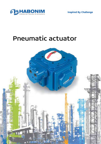
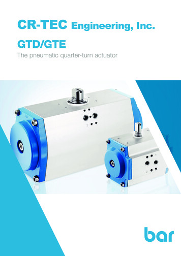
6. Entrapment ProtectionThe UL325 standard for gate operators requiresa minimum of two independent entrapmentprotection means for each entrapment zone. Anentrapment zone is defined as follows:For slide gates, any locations between a movinggate and a counter opposing edge or surfacewhere entrapment is possible up to a height of 6ft. (1.83m) above grade. Such locations occur if atany point in travel the gap between a moving gateand the fixed counter opposing edges or surfacesis less than 16 in. (406mm).For swing gates, locations between a movinggate or moving, exposed operator componentsand a counter opposing edge or surface whereentrapment is possible up to 6 ft (1.83m) abovegrade. Such locations occur if during any pointin travel:a. The gap between the bottom of a movinggate and the ground is greater than 4 in.(101.6 mm) and less than 16 in. (406 mm); orb. The distance between the center line of thepivot and the end of the wall, pillar, or columnto which it is mounted when in the open orclosed position exceeds 4 in. (101.6 mm).Any other gap between a moving gate andfixed counter opposing edges or surfacesor other fixed objects is less than 16 in. (406mm) (examples are walls, curbs, berms orother immovable objects).Potential entrapment zones are shown in Figure 1for slide and swing gates, but keep in mind theremay be other entrapment zones presented bythe actual installation and adjacent structures orlandscape that must be protected as well.Entrapment Protection Inputs - Typical Installation Diagram Utilizing PhotocellsOutsideGateClose Direction EyeOpenDirectionEye(Possible Entrapment Zoneif gate opens to 16 inchesfrom wall or fixed object)Close Direction EyeOpenDirectionEye(Possible Entrapment Zoneif gate opens to 16 inchesfrom wall or fixed object)www.ApolloGateOpeners.com (800) 878-7829 Sales@ApolloGateOpeners.com13
All Nice gate operators feature an InherentEntrapment System (IES) (UL325 Type A) thatmonitors the force on the gate during travel.This system protects in both the open andclose direction and reverses on contact with anobstruction. This IES system serves as one of themeans of entrapment protection.External sensors must be used to protect againstentrapment at each location where an entrapmentzone exists. The minimum number of externalsensors required to enable automatic operationof the gate operator is as follows: Swing Gates: One sensor in the Close direction(provided the gate in the open directionpresents no risk of entrapment.) Slide Gates: One sensor in the Open directionand one sensor in the Close direction.The gate operator tests for the presence of thesesensors, and if the required minimum numberis not found, the operator will only run usingcontinuous pressure on an Open/Close button,either on the controller, or an external device.147. Compatible External SensorsOnly the following external sensors have beenevaluated and tested with Nice gate systems andare approved to be used for protection againstentrapment: Nice Through-Beam Photo Eye BlueBus EMX IRB-RET Retro-reflective Photo Eye ASO Sentir Series Contact Edge Miller Edge GEM-103 Edge Sensor Converter EMX WEL-200 Wireless Edge Transmitter/Receiverwww.ApolloGateOpeners.com (800) 878-7829 Sales@ApolloGateOpeners.com
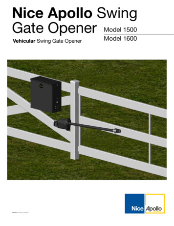
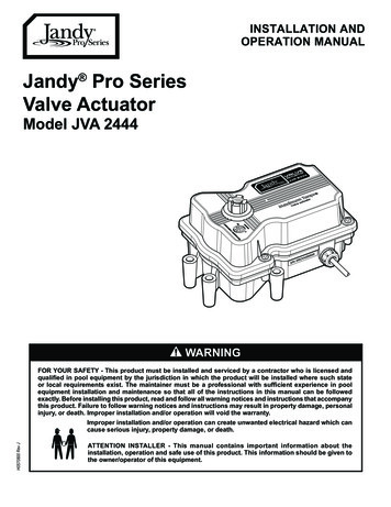
8 - 936 CIRCUIT BOARD LAYOUTLEARN BUTTONPROGRAM BUTTONSDUAL 7 SEGMENT STATUSDISPLAY WINDOWACCESSORYPOWER OUTPUTAND PROGRAMMABLEINPUT AACCESSORYPOWER OUTPUTAND STEP INPUTPROGRAM MENUCONTROL BUTTONSGATE OPERATIONCONTROL BUTTONSINPUTSACCESSORY POWEROUTPUTSOUTPUTSACCESSORYPOWER OUTPUTS andPROGRAMMABLE INPUT“C”EARTH GROUNDCONNECTION30AMOTOR CONTROLSPOWER INPUTCONNECTIONSwww.ApolloGateOpeners.com (800) 878-7829 Sales@ApolloGateOpeners.com15
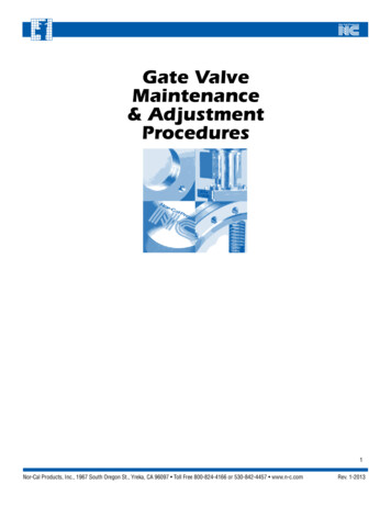
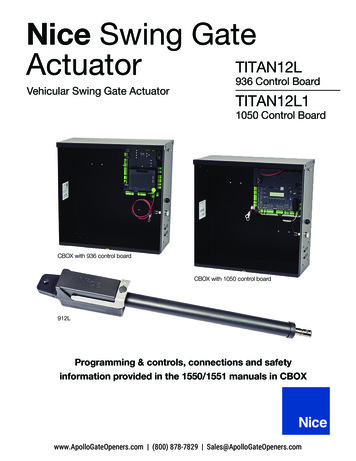
9 - 1050 CIRCUIT BOARD LAYOUTPower InputConnectionsMotor OutputConnections -SOLAR P.BATTERYMAIN DC POWER30A FUSEMOTORMOTOR 2SERIES 1050UL325 Compliant Monitored Safety Devices(s) required.AccessoryOutputConnectionsOXI/A ReceiverBlueBusConnectionP
1.1 TITAN12L/12L1 Swing Gate Actuator This manual provides documentation that covers the layout, construction, mechanical and electrical installation of TITAN12L/12L1 swing gate operators with the Nice brand 936 or 1050 control board. TITAN12L/12L1 swing gate operators are intended for residential gate installations only. Please consult