Transcription
PRINTER’S INSTRUCTIONS:INSTR,INSTL,RE-1 - LINEAR P/N: 217490 C - INK: BLACK - MATERIAL: 20 LB. MEAD BOND WITH 80 LB. WHITE COATED COVER - SIZE: 8.500” X 11.000” - SCALE: 1-1 - FOLDING: ALBUM-FOLD - BINDING: SADDLE-STITCHRE-1Residential TelephoneEntry SystemWith Built-in Wireless ReceiverInstallation,Programming,and Operation Instructions(760) 438-7000USA & Canada (800) 421-1587 & (800) 392-0123Toll Free FAX (800) 468-1340www.linearcorp.com
CONTENTSPRODUCT DESCRIPTION . . . . . . . . . . . . . . . . . . . . . . . . . .1INSTALLATION INFORMATION . . . . . . . . . . . . . . . . . . . . 2COMPONENT LOCATIONS . . . . . . . . . . . . . . . . . . . . . . . . 3WIRING DIAGRAM. . . . . . . . . . . . . . . . . . . . . . . . . . . . . . 4ENTRY SYSTEM MOUNTING . . . . . . . . . . . . . . . . . . . . . . 5TELEPHONE WIRING . . . . . . . . . . . . . . . . . . . . . . . . . . . 5TELEPHONE WIRING OPTIONS . . . . . . . . . . . . . . . . . . . . 6MULTIPLE UNIT INSTALLATIONS . . . . . . . . . . . . . . . . . . 7CONTROL WIRING. . . . . . . . . . . . . . . . . . . . . . . . . . . . . . 8POWER, BATTERY, & GROUND WIRING . . . . . . . . . . . . . . 9OPTIONAL REMOTE KEYPAD . . . . . . . . . . . . . . . . . . . . . 9OPTIONAL KEYSWITCH . . . . . . . . . . . . . . . . . . . . . . . . .10OPTIONAL CCTV CAMERA . . . . . . . . . . . . . . . . . . . . . . . 11PROGRAMMING ACCESS . . . . . . . . . . . . . . . . . . . . . . . . .12LOCAL PROGRAMMING ACCESS . . . . . . . . . . . . . . . . . . .18REMOTE PROGRAMMING ACCESS . . . . . . . . . . . . . . . . .18PROGRAMMING REFERENCE . . . . . . . . . . . . . . . . . . . . .19BASIC SYSTEM PROGRAMMING . . . . . . . . . . . . . . . . . . 20ENTRY CODE PROGRAMMING . . . . . . . . . . . . . . . . . . . . 20TRANSMITTER PROGRAMMING . . . . . . . . . . . . . . . . . . .21TELEPHONE PROGRAMMING . . . . . . . . . . . . . . . . . . . . .21ADVANCED SYSTEM PROGRAMMING . . . . . . . . . . . . . . 22SYSTEM ADJUSTMENTS . . . . . . . . . . . . . . . . . . . . . . . 24RE-1 OPERATION . . . . . . . . . . . . . . . . . . . . . . . . . . . . . 25RESIDENT PROGRAMMING QUICK REFERENCE . . . . . . 26SPECIFICATIONS . . . . . . . . . . . . . . . . . . . . . . . . . . . . . 27DIMENSION DRAWING . . . . . . . . . . . . . . . . . . . . . . . . . 27TROUBLESHOOTING . . . . . . . . . . . . . . . . . . . . . . . . . . . 27PROGRAMMING WORKSHEET . . . . . . . . . . . . . . . . . . . . 28LINEAR LIMITED WARRANTY . . . . . . . . . . . . . . . . . . . . 30FEATURES TWO-WAY SPEAKERPHONE CALL WAITING CALL FORWARDING DISTINCTIVE RINGS FOR ACCESS CALLS SEVEN ACCESS TIME ZONES TIMED “DO NOT DISTURB” PRIVACY FEATURE DIGITALLY SYNTHESIZED HUMAN VOICE PROMPTS RESIDENCE CONTROL OF RELAYS PROGRAMMABLE RELAY CONTROL PREFIXES 100 ENTRY CODE CAPACITY 1-6 DIGIT ENTRY CODE LENGTH EACH ENTRY CODE CAN BE PROGRAMMED TOACTIVATE EITHER OR BOTH RELAYS 100 TRANSMITTER CAPACITY SUPPORTS 24 BLOCKS OF TRANSMITTERS SUPPORTS MGT SAFETY EDGE TRANSMITTER INTERNAL CLOCK AND CALENDAR WITH BATTERYBACKUP EVENT LOG MEMORY RETAINS THE LAST 450SYSTEM EVENTS KEYPAD PROGRAMMABLE LOCALLY & REMOTELY PROGRAMMABLE WITH ATELEPHONE OR COMPUTER PROGRAMMING SOFTWARE BUILT-IN, CONNECTWITH ANY INTERNET BROWSER WEATHER-PROOF, TAMPER-RESISTANT HOUSING SUPERHETERODYNE RADIO RECEIVER INTEGRAL RADIO ANTENNA REMOTE KEYPAD SUPPORT BRIGHT WHITE LED DOWNLIGHT PIEZO SOUNDER 2 HEAVY DUTY FORM “C” (N.O. & N.C) RELAYOUTPUTS TIMED ANTI-PASSBACK KEYPAD LOCKOUT TACTILE KEY FEEL TWO DOOR SENSE/INHIBIT INPUTS TWO OPEN REQUEST INPUTS ACCESS KEYSWITCH PROVISION REMOVABLE TERMINAL BLOCKS OPTIONAL CCTV CAMERA WITH INFRAREDILLUMINATORS
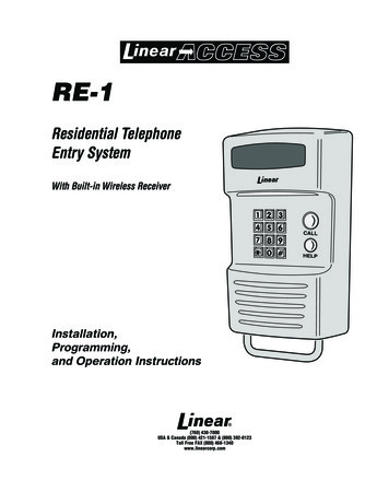
PRODUCT DESCRIPTIONLinear’s RE-1 Telephone Entry System is designed for residentialor light commercial access control applications. The speakerphone,keypad, radio receiver, and optional video camera are housed ina rugged enclosure that can be mounted to a pedestal or bolteddirectly to a wall. The die-cast keypad keys have bright, easy-toread graphics and are lit with an overhead light. The two operationbuttons; CALL and HELP, are machined for heavy-duty reliability.OperationArriving visitors will approach the unit and place a call to theresidence by pressing the CALL button. The RE-1 will acquire theresidence’s local telephone line and generate distinctive rings to thehouse telephones. The resident, knowing that the distinctive ring isoriginating from the access area, can answer any house telephoneand converse with the visitor. If the resident decides to grant accessto the visitor, they can activate either output relay in the RE-1 bypressing a key on the telephone’s keypad. If the resident decidesnot to grant access, hanging up or pressing a key will disconnectthe visitor’s call.Call WaitingIf the resident is using the telephone at the time a visitor calls, theRE-1 will sound beeps on the telephone line to announce that avisitor is calling. The resident can press a key on the telephone toplace the outside caller on hold and communicate with the visitor.After granting or denying access to the visitor, the outside caller willbe re-connected to the resident.Call ForwardingSystem FeaturesTime ZonesThe RE-1 contains an internal clock and calendar. Sevenprogrammable “time zones” allow setting time periods to schedulesystem functions. Each time zone can be active or inactive on certaindays. Keypad entry codes, wireless transmitters, automatic accesscontrol, call forwarding, and the “Do Not Disturb” feature can eachbe set to only be active during a specific time zone period. Up to ten“holiday” days can be programmed. Each of the seven time zonescan be set to be active or inactive during a holiday.Portal SupervisionThe SENSE/INHIBIT input can be used two ways. If programmedfor “door sense”, a switch on the door detects forced entry or doorajar situations. If programmed for “inhibit”, the input can be wired toa “service” switch or automatic timer that will disable the Relay #1when required.Hardwired ActivationThe OPEN REQUEST input can be wired to an exit loop detectoror exit photo beam to allow automatic exit activation. An emergencyaccess keyswitch can be mounted in the RE-1 case to allow keyedentry for authorized personnel.Access SecurityThe “anti-passback” feature allows the option of preventing the use ofthe same code or the same transmitter again before the programmedtime elapses. The “keypad lockout” feature discourages tampering bydisabling the keypad for one minute after a programmable numberof incorrect entry codes has been entered at the keypad.Programmable call forwarding allows the RE-1 to dial any selectedtelephone number when a visitor presses the CALL button. Forexample, with call forwarding enabled, the RE-1 could dial a cellphone to contact the resident while outside or away from theresidence. The resident will be able to communicate with the visitorand grant or deny access from the remote telephone.Event LogAlternate NumbersThe system’s built-in programming software can be accessed on-siteor off-site using a computer with any Internet browser. The software’sgraphic display of each of the programming steps make programmingeasy. Without a computer, the RE-1 can be programmed with itsmain keypad, from any local telephone connected to the same line,or by calling from any remote telephone.The EEPROM memory retains all entry codes, transmitterinformation, and programming, even without power.For installations where multiple residences exist inside the samecontrolled opening (such as a guest house or granny flat) threealternate calling numbers can be programmed. The alternatenumbers can be called by entering a short code at the keypad.Local ControlThe resident can issue control commands from the local telephoneswithout a call from a visitor. By dialing a specific series of digits, theresident can control either of the two relays. The resident can alsoinitiate voice communications with the entry system.Access MediaUp to 100 entry codes, from 1 to 6 digits in length, can beprogrammed. Each entry code can activate either, or both, of therelay outputs. Linear’s Model AM-KP keypad can be used as asecondary remote keypad for the RE-1.Up to 24 sets of block coded MegaCode transmitters (up to100 transmitters total) can be used to gain access through theRE-1’s built-in radio receiver. Each transmitter can be individuallysuspended or re-activated. One facility code can be programmedto identify each block of transmitters. Programming of individual(non-block coded) transmitters is not supported by the RE-1.An access log of up to 450 events is stored in the unit’s memory.System activity is logged as it occurs with the date and time of theevent. The access log data can be retrieved locally or remotely witha computer through the RE-1’s built-in modem.Local & Remote ProgrammingObstacle DetectionLinear’s Model MGT safety edge transmitter is compatible with theRE-1 This MGT detects and transmits obstacle events to the RE-1receiver. Obstacle signals from an MGT transmitter will activateRelay #2.Alarm InterfaceRelay #2 can be programmed for alarm shunt to bypass an alarmloop during entry, or alarm trigger to cause an alarm during forcedentry. Four activation options are available for Relay #2.Voice SynthesizerA built-in voice synthesizer sounds voice prompts through thespeaker, local and remote telephones.1
INSTALLATION INFORMATIONBefore beginning installation, please review the entire instructionsand become familiar with the system’s operation, wiring, andprogrammable options.System LocationFor pedestrian door or gate installations, mount the Entry Systemon a rigid wall near the controlled door. Avoid mounting the unitin a location where regular mechanical shock will occur due to aslamming door or spring loaded pedestrian gate.For vehicular gate installations, mount the Entry System in clearview of the gate, but far enough from the gate so the user cannottouch the gate from the keypad. WARNING FOR ALL GATE INSTALLATIONS: TO AVOIDSERIOUS INJURY OR DEATH, MAKE SURE THAT THEUNIT IS FAR ENOUGH FROM THE GATE SO THAT THEUSER CANNOT TOUCH THE GATE WHILE OPERATINGTHE KEYPAD. HOWEVER, FOR SAFETY, THE GATEMUST BE FULLY VISIBLE FROM THE KEYPAD.RFI Filter InstallationAn in-line ferrite RFI filter has been included with this unit to installduring the wiring of the RE-1 Residential Telephone Entry System. NOTE: To insure FCC Part 15 Class B compliance, the following stepsmust be performed at the time the RE-1 is installed.1. Open the ferrite RFI filter case by gently pulling on the side lockingtab and swinging the case open (see Figure 1). CAUTION: The ferrite parts of the RFI filter are fragile.DO NOT DROP THE FILTER ON A HARD SURFACE!Damage to the filter may result.2. After completing the RE-1 installation, route all wires except theAC transformer and telephone lines through the grove in the ferritecore of the RFI filter. The filter must be installed outside of the RE-1case. With the wires captured inside, close the ferrite RFI filter caseand snap it shut (see Figure 1). NOTE: Be sure the filter is located no further than two inches from therear case cover of the RE-1.NOTE: INSTALLATION OF THE RFI FILTER WILLINSURE MAXIMUM RADIO RECEPTION RANGEFOR ACCESS TRANSMITTERSPULL ON PLASTIC TABTO UNLOCK FILTER CASERFI FILTERINSTALLEDWITHIN 2"OF RE-1 CASESWING FILTERCASE OPEN Minimum size of 24 AWG for up to 800 feet. Minimum size of 22 AWG for up to 1600 feet. Minimum size of 20 AWG for up to 2200 feet. Minimum size of 18 AWG for up to 3600 feet.DO NOT ROUTE TELEPHONE AND AC WIRING INSIDE THESAME CONDUIT. Route all telephone wires inside a dedicatedconduit that is at least six inches away from any AC line wiring.Power SupplyUse the supplied 16-volt 20-VA transformer to power the RE-1.DO NOT POWER ANY OTHER EQUIPMENT FROM THE SAMETRANSFORMER, use a separate power supply. Keep the systempower wires as short as practical to reduce the chance of noise andhum pickup. For low voltage power wire runs up to 100 feet, use 18 AWG, THHN600-volt insulated wire. For low voltage power wire runs up to 200 feet, use 16 AWG, THHN600-volt insulated wire. Use 22 AWG or larger (depending on the load) for all otherconnections.ALWAYS REMOVE POWER PRIOR TO SERVICINGEarth GroundTo avoid damage to the unit from static discharges, connect theRE-1’s EARTH GROUND and case ground terminals to a goodearth grounding point within 10 feet. The case ground terminal isthe #8 screw located on the backplate above the wire entry hole.Also, the RE-1’s Telephone Bypass Module must be grounded toprovide surge protection for the telephone line. Suggested wiringsize is 12 AWG for earth ground.Removable Terminal StripsFor convenience, the RE-1 is provided with removable terminalstrips. It is important that these strips be removed evenly in order toavoid causing permanent damage to them.1. Be certain power is off before removing or installing these strips.2. With a small screwdriver, gently slide the blade between the terminalstrip and protective label.3. Slightly pry first one end, then the other, and then the middle. Repeatthe process until the terminal strip can be removed straight off the circuitboard by hand. Be very careful to not damage circuit board traces.4. When re-installing the terminal strips, press down straight and evenly.Do not remove or install one end first. This will bend pins on the circuitboard, which will damage the terminal strip internally. This damageis permanent and can not be repaired by simply straightening thepins on the circuit board. NOTE: Unscrew the terminal screws several turns before insertingwires.PHONE ANDTRANSFORMER WIRESOUTSIDE OF FILTERFERRITECOREFigure 1. RFI Filter Installation2Telephone WiresThe quality of the system’s audio communications is related to thetype of telephone wire and its installation. Noise and hum can beintroduced into the telephone wires. Use only high-quality telephonewire rated for direct underground burial. All telephone wire shouldbe twisted-pair.
13314121142CALL515161016177918218COMPONENT LOCATIONS123456KEYPADDie-cast metal 12-key keypad with tactile action. For systemprogramming and keying in entry codes.DOWNLIGHTIlluminates keypad and visitor operation buttons. The light can beprogrammed to operate dusk to dawn and adjusts its time dependingon the system’s geographic location.OPTIONAL CCTV CAMERALocation for the optional Model RE-BWC1 CCTV camera. The cameraviews the keypad area and has infrared lighting for nighttime use.MICROPHONEThe high-sensitivity microphone monitors sound at the keypad areafor the entry system’s speakerphone.CALL BUTTONPressing this button causes the system to call the residencetelephones with a distinctive ring signal.HELP BUTTONPressing this button causes the system to play the help message toinstruct the visitor on system use.192012 RELAY TERMINAL BLOCKFor Relay #1 and Relay #2 output connections to the access controldevices.13 RELAY INDICATORSIndicators for Relay #1 and Relay #2 will light when the relay isactivated.14 ANTENNA TERMINAL BLOCKFor shield and center conductor connection of the coax cable fromthe system’s built-in radio antenna.15 LINE MONITOR JUMPERFor testing and troubleshooting. Remove jumper to listen totelephone line audio through the speaker.16 DIGITAL SPEECH VOLUME CONTROLControls the audio level of the voice synthesizer. This adjustmenteffects the audio level of the voice synthesizer and system tone fromthe speaker.17STATUS INDICATORSSix indicators light to display system power, radio, and modemstatus.18 VIDEO CONNECTORFor cable connection to a video monitor. (Optional Model RE-BWCCCTV camera required).7SPEAKERWeatherproof speaker for system operation and programming.8INTEGRAL ANTENNAHidden antenna receives wireless radio signals from transmitters.19 CAMERA CONNECTORProvides power and video connection for the optional Model REBWC CCTV camera.9OPTIONAL KEYLOCKLocation for mounting access keylock. (MEDECO keylock withstainless steel cover shown).20 RESTART BUTTONPressing this button restarts the system. This button DOES NOTerase any programming data.10 MAIN TERMINAL BLOCKFor power, backup battery, sense inputs, open request inputs, andremote keypad connections.1121 TELEPHONE TERMINAL BLOCKFor telephone line and earth ground connections.SPEAKERPHONE VOLUME CONTROLControls the audio level produced by the speaker duringcommunications between the visitor and the resident.3
WIRING DIAGRAMRELAY#1RELAY#2N.C.COMN.O.N.C.N.O.RELAY RATING:3 AMPS AT30 VOLTS AC OR DCMAXIMUMCOMTYPICALGATE INSTALLATIONWIRINGRE-1TELEPHONE ENTRYSYSTEMGATEOPERATOROPEN16 VAC20 VATRANSFORMERTRANSFORMERTRANSFORMERBATTERY NEGATIVEBATTERY POSITIVESENSE #1OPEN #1CASEGROUNDSENSE #2OPEN #2COMMONTO HOUSEPHONESKEYPAD CLKKEYPAD DVALKEYPAD DAT 0KEYPAD DAT 1KEYPAD GNDKEYPAD PWRTO ERING RE-1TIP HOUSE TELEPHONEBYPASSRING RE-1MODULETIP TELCOEARTHGROUNDRINGTELCOTIPGROUNDSTAKE10' MAXIMUMWIRE RUNRELAY#2N.C.COMN.O.N.C.N.O.COMNOTE: A MAGNETIC LOCK ANDDOOR STRIKE ARE BOTH SHOWN,TYPICALLY ONLY ONE IS USEDRELAY RATING:3 AMPS AT30 VOLTS AC OR DCMAXIMUMTIP10' MAXIMUMWIRE RUNHOUSE TELCOTYPICALDOOR INSTALLATIONWIRINGRINGMAGNETICDOOR LOCKRE-1TELEPHONE ENTRYSYSTEMNOTE: DO NOT POWERTHE LOCKING DEVICE FROMTHE RE-1 TRANSFORMERELECTRICDOOR RBATTERY NEGATIVEBATTERY POSITIVESENSE #116 VAC20 VATRANSFORMEROPEN #1SENSE #2OPEN #2CASEGROUNDCOMMONTO HOUSEPHONESKEYPAD CLKKEYPAD DVALKEYPAD DAT 0KEYPAD DAT 1KEYPAD GNDKEYPAD PWRTO TELCOLINEEARTHTIPRINGTIPRINGHOUSE TELCOTIPHOUSERING RE-1TIP HOUSE TELEPHONEBYPASSRING RE-1MODULETIP TELCOEARTHGROUNDRINGTELCOTIP10' MAXIMUMWIRE RUNGROUNDSTAKE4RINGGROUNDSTAKE10' MAXIMUMWIRE RUN
TELEPHONE WIRINGENTRY SYSTEM MOUNTINGPedestal MountingThe RE-1 Entry System can be mounted on a standard pedestal.1. Open the RE-1 case by removing the two security screws with thewrench provided (see Figure 2).2. Use four security bolts and locking nuts to secure the backplate to thepedestal (see Figure 3).Wall MountingThe RE-1 Entry System can be mounted directly to a wall or flatsurface.1. Open the RE-1 case by removing the two security screws with thewrench provided (see Figure 2).2. Use the appropriate fasteners to secure the system’s backplate to themounting surface. When mounting the system to a concrete wall, useconcrete wedge anchors (see Figure 4).The RE-1 connects between the incoming telephone line of theresidence and local telephone sets.Telephone Bypass ModuleThe RE-1’s Telephone Bypass Module provides surge protection anda switch to remove the RE-1 from the telephone line and re-connectthe local telephones to the telephone system. ALL TELEPHONEWIRING FOR THE RE-1 MUST PASS THROUGH THE BYPASSMODULE.The bypass module is housed in a weather-resistant enclosure andshould be located in an area that is easily accessible to the resident.In case of system trouble, the resident can use the bypass switch toremove the RE-1 from the telephone system.Telephone Wiring DO NOT ROUTE TELEPHONE AND AC WIRING INSIDE THE SAMECONDUIT. Route all telephone wires inside a dedicated conduit that isat least six inches away from any AC line wiring. All telephone wiring must be made on the “house” side of the telephonecompany’s demarcation device (the terminal block where the telephoneline connects to the residence). If any security system or personal alert system at the residence isconnected to the telephone line, be sure that it is connected to the lineahead of the Telephone Bypass Module using a RJ-31X or RJ-38Xinterface.REMOVE THE TWOSECURITY SCREWSTO OPEN THE CASE Use only high-quality telephone wire rated for direct undergroundburial. All telephone wire should be twisted-pair with a minimum size of24 AWG.Typical Telephone WiringFigure 2. Opening the RE-1 CasePEDESTALMOUNTINGPEDESTALMOUNT BACKPLATEWITH SECURITY BOLTSAND LOCKNUTSCAUTION!BE SURE THE MOUNTING HARDWAREDOES NOT EXTEND MORE THAN 1/2"INSIDE THE BACKPLATE ORELECTRICAL DAMAGE MAY OCCUR1. Connect the bypass module’s EARTH GROUND terminal to a goodearth ground.2. Before connecting the incoming telephone line to the bypass modulecheck the polarity of the wires with a DC voltmeter. Connect thenegative wire (RING - usually green) to the bypass module TELCORING terminal. Connect the positive wire (TIP - usually red) to thebypass module TELCO TIP terminal.3. Connect the resident’s local telephone line RING (usually green) tothe bypass module HOUSE RING. Connect the local telephone lineTIP (usually red) to the bypass module HOUSE TIP terminal.4. Connect the RE-1 TELCO RING to the bypass module RE-1 TELCORING terminal. Connect the RE-1 TELCO TIP to the bypass moduleRE-1 TELCO TIP terminal.5. Connect the RE-1 HOUSE RING to the bypass module RE-1 HOUSERING terminal. Connect the RE-1 HOUSE TIP to the bypass moduleRE-1 HOUSE TIP terminal.Figure 3. Pedestal Mounting RINGCASEGROUND SCREWWALLMOUNTINGTO HOUSEPHONESUSE WEDGE ANCHORSFOR CONCRETE OROTHER APPROPRIATEANCHORS FOR DIFFERENTMATERIALSCAUTION!BE SURE THE MOUNTING HARDWAREDOES NOT EXTEND MORE THAN 1/2"INSIDE THE BACKPLATE ORELECTRICAL DAMAGE MAY OCCURFigure 4. Wall Mounting BackplateTO ERING RE-1TIP HOUSE TELEPHONEBYPASSRING RE-1MODULETIP TELCOEARTHGROUNDRINGTELCOTIPGROUNDSTAKEFigure 5. Telephone Wiring5
TELEPHONE WIRING OPTIONSShared LineThis is the standard configuration. The telephone line is routedthrough the RE-1 to the house phones. Pressing the Call button onthe RE-1 will cause the RE-1 to disconnect the house phones fromthe telephone company line and generate a ring signal that is heardon the house phones.Intercom ModePressing the Call button on the RE-1 will cause the RE-1 to generatea ring signal as if it were an intercom station. A live phone line is notused and the RE-1 provides power for the remote intercom phone. NOTE: In this mode, remote programming, call forwarding or alternateresident calling is not available.See PPN #52 for programming options.CASEGROUNDTO HOUSEINTERCOMTELEPHONESRE-1ENTRYSYSTEMTO HOUSE TELCORINGTIPRINGTIPHOUSERING RE-1TIP HOUSE TELEPHONEBYPASSRING RE-1MODULETIP TELCOEARTHGROUNDRINGTELCOTIPHOUSERING RE-1TIP HOUSE TELEPHONEBYPASSRING RE-1MODULETIP TELCOEARTHGROUNDRINGTELCOTIPEARTH10' MAXIMUMWIRE RUNGROUNDSTAKETIP10' MAXIMUMGROUND WIRE YSTEMCASEGROUNDFigure 6. Shared Line WiringDedicated LinePressing the Call button on the RE-1 will cause the RE-1 to siezethe phone line and dial out to an outside number.See PPN #54 for programming options.Figure 8. Intercom Mode WiringRing Down ModePressing the Call button on the RE-1 will cause the RE-1 to siezethe phone line and provide immediate communications with thePBX system.See PPN #54 for programming ONECOMPANYEARTHTIPRINGTIPRINGHOUSE TELCORING RE-1TIP HOUSE TELEPHONEBYPASSRING RE-1MODULETIP TELCOEARTHGROUNDRINGTELCOTIP10' MAXIMUMWIRE RUNGROUNDSTAKEFigure 7. Dedicated Line WiringTOPBXSYSTEMHOUSEGROUNDSTAKE10' MAXIMUMWIRE RUNRINGTIPHOUSERING RE-1TIP HOUSE TELEPHONEBYPASSRING RE-1MODULETIP NGHOUSEFigure 9. Ring Down Mode Wiring6RE-1ENTRYSYSTEMCASEGROUNDGROUNDSTAKE
MULTIPLE UNIT INSTALLATIONSAny of the four basic operation modes (Shared Line, Dedicated Line,Intercom, and Ring Down) may be used with multiple RE-1s in thesame installation. The telephone line wiring is “daisy chained” (thetelephone line routes through one unit to the next) as shown below.Always connect the telephone line to TIP, and - to RING.The Telephone Bypass Module only performs the bypass functionin the Shared Line Mode, but it will provide extra electrical surgeprotection in all modes. A surge on the TELCO terminals will besuppressed through the EARTH GROUND terminal. Always useseparate AC transformers to power each RE-1.When multiple units are connected together, only two units can becontrolled by resident telephone commands, and only one unitcan be programmed to answer the telephone (PPN #33) for remotetelephone commands. Remote programming via computer is notsupported when using multiple RE-1s.SHARED LINEMODECASEGROUNDTIPEARTHRINGTIPCASEGROUNDHOUSE E NGFROMTELEPHONECOMPANYOR PBXGROUNDSTAKEFIRSTRE-1ENTRYSYSTEMPROGRAM ALLRE-1 UNITS FOR"RING DOWN MODE"(PPN #54)HOUSETIPRE-1 RINGTELEPHONE HOUSE TIPBYPASSMODULERE-1 RINGTELCO TIPEARTHRINGGROUNDTELCOTIPGROUNDSTAKEGROUNDSTAKEIF DESIRED, CHANGERESIDENT RESPONSE KEYS(PPN #71)RINGRINGHOUSE TELCOTIPHOUSE TELCOTIPRE-1 RINGTELEPHONE HOUSE TIPBYPASSMODULERE-1 RINGTELCO DPROGRAM ALLRE-1 UNITS FOR"CALL FORWARDING"(PPN #54)RINGRING COMPANYCASEGROUNDHOUSE TELCOHOUSE TELCORINGTIPEARTHRINGTIPHOUSEDEDICATED LINEMODEHOUSEDO NOT CONNECTTO A LIVE TELEPHONE GROUNDTOINTERCOMTELEPHONESRINGRE-1 RINGTELEPHONE HOUSE TIPBYPASSMODULERE-1 RINGTELCO TIPEARTHRINGGROUNDTELCOTIPPROGRAM THISRE-1 UNIT ONLY FOR"INTERCOM MODE"(PPN #52)CASEGROUNDRINGTIPEARTHRINGTIPHOUSE Set the other unit’s command prefix toIn the case of simultaneous visitors at different units when usingthe Shared Line Mode, putting one RE-1 “on hold” to communicatewith the second RE-1, then returning to the first RE-1 is notrecommended. Instead, finish all communications with the first RE-1before servicing the second RE-1. Simultaneous visitors at multipleunits used on a single line wired in the Ring Down Mode will causea “conference call” effect between unitsHOUSE TELCOHOUSE TELCORINGTOHOUSETELEPHONES Set one unit’s command prefix TEMCommand Prefix for Multiple UnitsProgramming and relay control may be through the individual RE-1keypads or through the house telephone(s) when using the SharedLine or Intercom Modes. To support using the house telephone(s)to issue commands, each RE-1 must be programmed to a different“command prefix” (PPN #72).RINGTIPRE-1 RINGTELEPHONE HOUSE TIPBYPASSMODULERE-1 RINGTELCO STAKEGROUNDSTAKEFigure 10. Multiple Unit Wiring7
Door or Pedestrian Gate ControlCONTROL WIRINGGate Control1. Route two wires between the gate and the RE-1. Connect the gateoperator’s OPEN terminals to the RE-1 Relay #1 COM & N.O.terminals. NOTE: For operator wiring specifics, refer to the gate operator’s wiringdiagram.2. If an access keyswitch is required refer to the Optional Keyswitchsection of this manual for details on keyswitch wiring and installation.3. If an external timer for preventing access at certain times is required,route two wires from the RE-1 to the timer contacts. Connect the timercontacts to the RE-1 SENSE #1 and COMMON terminals. NOTE: If the sense input is going to be used as an inhibit input, it mustbe programmed to select that input type. See programming PPN #29.GATEOPERATOR(BEHIND GATE)RE-1ENTRYSYSTEM4 WIRES FORTELEPHONE1. Install a low voltage electric door strike or magnetic lock as a lockingdevice for the door or pedestrian gate.2. Install the power supply or transformer for the locking device. DO NOTPOWER THE RE-1 FROM THIS POWER SUPPLY.3. Connect one wire from the power supply to one wire from the lockingdevice.4. Route two wires between the locking device and the RE-1. Connectone wire to the remaining wire of the locking device. Connect theother wire to the remaining wire of the power supply. For a door strike, connect the wires to the RE-1 Relay #1 COM & N.O.terminals. For a magnetic lock, connect the wires to the RE-1 Relay #1 COM &N.C. terminals.5. If an access keyswitch is required refer to the Optional Keyswitchsection of this manual for details on keyswitch wiring and installation.6. To use the door sense feature to detect forced entry or door ajarconditions, install a normally closed door switch on the door orpedestrian gate and route two wires from the switch to the RE-1.Connect the door sense switch to the RE-1 SENSE #1 and COMMONterminals. See programming PPN #24 & #27 to define when Relay #2will activate based on the sense input.4 WIRES FORTELEPHONE2 WIRESFOR DOORSENSESWITCHNOTE: ROUTE TELEPHONEWIRES AWAY FROMPOWER IKENOTE: ROUTE TELEPHONEWIRES AWAY FROM POWERWIRES2 WIRES FOR RE-1POWER FROMTRANSFORMER2 WIRESFOR DOORSTRIKE2 WIRES FOR DOORSTRIKE POWER FROMPOWER SUPPLY2 WIRES FROMTRANSFORMERFOR RE-1 POWER2 WIRES FROM RE-1TO GATE OPEN TERMINALSFigure 11. Gate Installation ExampleRELAY#1Figure 13. Door Installation SELECTRICDOOR STRIKERE-1TERMINALSREQUIRED WIRINGTRANSFORMERTRANSFORMERTRANSFORMERBATTERY NEGATIVEBATTERY NEGATIVEBATTERY POSITIVESENSE #1OPEN #1NOTE: IN THIS EXAMPLESENSE #1 TERMINAL ISSET AS AN INHIBIT INPUTINHIBITTIMERREQUIRED WIRINGBATTERY POSITIVESENSE #1OPTIONAL WIRINGOPEN #1SENSE #2SENSE #2OPEN #2ACCESSKEYSWITCHCOMMONDOORSENSESWITCHOPEN #2COMMONKEYPAD CLKKEYPAD CLKKEYPAD DVALKEYPAD DVALKEYPAD DAT 0KEYPAD DAT 0KEYPAD DAT 1KEYPAD DAT 1KEYPAD GNDKEYPAD GNDKEYPAD PWRKEYPAD PWRFigure 12. Gate Installation Wiring8DOOR STRIKEPOWER SUPPLYTRANSFORMEROPTIONAL WIRINGACCESSKEYSWITCHFigure 14. Door Installation Wiring
POWER, BATTERY, & GROUND WIRINGOPTIONAL REMOTE KEYPADPower Wiring NOTE: DO NOT APPLY POWER UNTIL THE INSTALLATION ISCOMPLETE.1. Route two wires between the RE-1 and the power transformer. For power wire runs up to 100 feet, use 18 AWG, THHN 600-voltinsulated wire. For power wire runs up to 200 feet, use 16 AWG, THHN 600-voltinsulated wire.2. Connect the wires to the transformer
For vehicular gate installations, mount the Entry System in clear view of the gate, but far enough from the gate so the user cannot touch the gate from the keypad. WARNING FOR ALL GATE INSTALLATIONS: TO AVOID SERIOUS INJURY OR DEATH, MAKE SURE THAT THE UNIT IS FAR ENOUGH FROM THE GATE SO THAT THE USER CANNOT TOUCH THE GATE WHILE OPERATING