Transcription
Protocol GuideFor Third-Party ControllersGlobalViewer EnterpriseServer-Based AV Resource Management Software68-1607-01 Rev. G01 19
Conventions Used in this GuideNotificationsThe following notifications are used in this guide:NOTE: A note draws attention to important information.Software CommandsCommands are written in the fonts shown here: AR Merge Scene,,Op1 scene 1,1 B 51 W C[01] R 0004 00300 00400 00800 00600 [02] 35 [17] [03]E X! *X1&* X2)* X2#* X2! CE}NOTE: For commands and examples of computer or device responsesmentioned in this guide, the character “0” is used for the number zero and“O” represents the capital letter “o.”Computer responses and directory paths that do not have variables are written in the fontshown here:Reply from 208.132.180.48: bytes 32 times 2ms TTL 32C:\Program Files\ExtronVariables are written in slanted form as shown here:ping xxx.xxx.xxx.xxx —tSOH R Data STX Command ETB ETXSelectable items, such as menu names, menu options, buttons, tabs, and field names arewritten in the font shown here:From the File menu, select New.Click the OK button.Copyright 2019 Extron Electronics. All rights reserved.TrademarksAll trademarks mentioned in this guide are the properties of their respective owners.The following registered trademarks , registered service marks(SM), and trademarks (TM) are the property of RGB Systems, Inc. orExtron Electronics (see the current list of trademarks on the Terms of Use page at www.extron.com):Registered Trademarks ( )Cable Cubby, ControlScript, CrossPoint, DTP, eBUS, EDID Manager, EDID Minder, Extron, Flat Field, FlexOS, Glitch Free, Global Configurator,Global Scripter, GlobalViewer, Hideaway, HyperLane, IP Intercom, IP Link, Key Minder, LinkLicense, LockIt, MediaLink, MediaPort,NetPA, PlenumVault, PoleVault, PowerCage, PURE3, Quantum, Show Me, SoundField, SpeedMount, SpeedSwitch, StudioStation,System INTEGRATOR, TeamWork, TouchLink, V‑Lock, VideoLounge, VN‑Matrix, VoiceLift, WallVault, WindoWall, XTP, XTP Systems, and ZipClipRegistered Service Mark(SM) : S3 Service Support SolutionsTrademarks ( )AAP, AFL (Accu‑Rate Frame Lock), ADSP (Advanced Digital Sync Processing), Auto‑Image, AVEdge, CableCover, CDRS (Class DRipple Suppression), Codec Connect, DDSP (Digital Display Sync Processing), DMI (Dynamic Motion Interpolation), Driver Configurator,DSP Configurator, DSVP (Digital Sync Validation Processing), eLink, EQIP, Everlast, FastBite, FOX, FOXBOX, IP Intercom HelpDesk, MAAP,MicroDigital, Opti-Torque, PendantConnect, ProDSP, QS‑FPC (QuickSwitch Front Panel Controller), Room Agent, Scope‑Trigger, ShareLink, SIS,Simple Instruction Set, Skew‑Free, SpeedNav, Triple‑Action Switching, True4K, Vector 4K, WebShare, XTRA, and ZipCaddy
ContentsIntroduction. 1Communication. 12About this Manual. 1About GlobalViewer Enterprise. 1Features. 1For Further Information. 2Communication Overview. 12Message Packet Structure. 12Header. 12Body. 13Character Escaping. 15Messages Between the Controller and GVE . 15Special Rules. 15Messages from the Controller. 15Messages to the Controller from GVE. 20Special Messages. 21Requirements and Setup. 3Requirements. 3Setup Overview. 4Add a Room and Location. 4Add a Location. 5Add a GVE Room. 5Add a Third-Party Controller to GVE. 7Add Attached or Controlled Devices. 8Add Input Sources. 10Add Device Statuses. 11Develop Controller Code. 11Support. 22Necessary Coding Modification. 22Technical Publications StandardsGlobalViewerandEnterpriseStyles Introduction Contentsiii
GlobalViewer Enterprise Contentsiv
IntroductionThis section describes the main features of GlobalViewer Enterprise (GVE) and provides anoverview of this protocol guide. Topics that are covered include: About this Guide About GlobalViewer Enterprise GVE Features For Further InformationAbout this GuideThis guide documents the protocol used for third-party controllers to function withGlobalViewer Enterprise. It is expected that the user of this document is familiar withthird‑party software development.Within this manual, the terms “GlobalViewer Enterprise” and “GVE” refer to the GlobalViewerEnterprise application and are interchangeable.As GlobalViewer Enterprise is updated, this protocol may change. Future versions ofGlobalViewer Enterprise will support more commands. As updates arise, changes to codingfor third-party controllers may be required.About GlobalViewer EnterpriseGVE is a multi-user, web-based, global management application that aids audio/video (AV)network administrators with monitoring and managing all of the devices across their AVnetworks. This application manages controllers and their display devices, such as projectorsor LCD or plasma monitors.GVE also takes inventory of other devices attached to the controller, such as media players,switchers, lighting devices, and document cameras. With this application, monitoring andmanaging AV devices can be accomplished from any location with web browser access.In GVE 2.7, there are three types of controllers: Extron Configurable (see GlobalViewer Enterprise Help file) Third-party controllers (described in this protocol guide) Extron Programmable (see GlobalViewer Enterprise Protocol Guide for ProgrammableControllers)GVE FeaturesGlobalViewer Enterprise supports most popular browsers, including: Microsoft Internet Explorer Microsoft Edge Mozilla Firefox Safari Google Chrome GlobalViewer Product EnterpriseName Section IntroductionTitle 1
The application runs from an easy-to-learn graphical user interface (GUI) and supplies acomprehensive set of reporting capabilities.GVE enables AV network administrators to: Import an existing AV system using one or more Global Configurator configuration files. Set user permissions for complete or regional (partial) access to the AV network andGVE tools. Set device schedules and monitors. Audit and manage AV equipment assets. Control devices on the AV network. Capture all host-to-controller communications in user logs. Generate equipment usage reports.GVE Features Not Supported by Third-party Control SystemsGVE Help Desk room control The Room Control tab lists the controller name, model name, MAC address, firmwareversion, IP address, gateway, subnet mask, and DHCP status. It does not show animage of the controller front panel. The Device Status tab displays device name, device type, status, controller port type,lamp cost, connection, power, device status, lamp hours, max lamp hours, operationhours, and filter hours.For Extron controllers that have been configured with GCP, the Device Status taballows you to control and view command status. This is not possible for third-partycontrollers.GVE schedule commandsGVE schedule commands for controllers are not executed on third-party controllers. TheAdd a Schedule wizard displays a warning stating this.GVE time syncGVE time sync schedule commands are not executed on third-party control systems.NOTE: This applies only to IP Link controllers.For Further InformationFor further information regarding GVE, visit www.extron.com/gveFor any questions regarding this protocol or support for GVE, ewer Enterprise Introduction2
Requirements andSetupThis section describes the requirements to communicate with third-party controllers andhow to set up these controllers in GVE. Topics that are covered include: Requirements Setup Overview Add a Room and Location Add a Third-Party Controller to GVE Add Attached or Controlled Devices Add Input Sources Add Device Statuses Develop Controller CodeRequirementsNOTE: It is expected that the user of this document is familiar with third-party softwaredevelopment.GVE communicates with third-party controllers over UDP and TCP protocols. Status messages sent from the controller to the GVE PC or server use UDP port 5555.This cannot be changed. Control messages sent from the GVE PC or server to the controller use TCP port 5555.This can be changed in GVE Configurator. The user must have access to the Controller Manager option and Location/Roomoption in GVE to create GVE rooms. The user needs to obtain information regarding the controller MAC address, IP addressor host name, firmware version, DHCP, subnet mask, gateway address, time zone, andDST mode. GVE supports all of the command and status items listed in the CommandsSupported Table, starting on page 17. It is preferred that the user provide as muchinformation as possible about the controller in order to maximize GVE capability.GlobalViewer Enterprise Requirements and Setup3
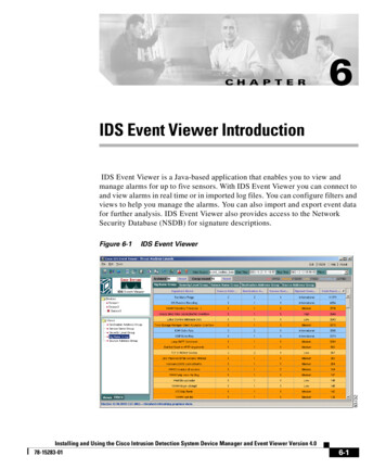
Setup OverviewA third-party controller and its attached or controlled devices are added manually to GVE.The steps below enable management of these controllers and devices through GVE.In the setup process, the user does the following:1. Defines the location of a third-party controller and any attached devices.2. Adds a third-party controller to GVE.3. Adds attached or controlled devices and places them in user-specified locations.4. Develops controller code.Add a Room and LocationIn order to add a third-party controller and any managed devices, you must designate theirlocation and room. Create a location if one has not already been created. Then, add a roomwithin that location.Definitions Building — A collection of locations and rooms. It can refer to a collection of floorswithin a physical building. Location — A collection of other locations and rooms. It can refer to a suite of rooms,an individual floor, or a group of floors. Room — A place where a controller or other device is located.NOTE: Controllers and devices must belong to a room and not a location.Tree ManagerIf a location already exists, skip the Add a Location instructions and proceed to the Add aGVE Room instructions. To begin defining a location:1. Log in to GlobalViewer Enterprise.2. Click System Menu on the navigation bar (see figure 1, 1).3. Click the Tree Manager icon (see the figure to the right).The Tree Manager screen opens.Figure 1.Locations and Rooms Screen4. See Add a Location and Add a GVE Room (on the next page) to add a location or aroom.GlobalViewer Enterprise Requirements and Setup4
Add a Location1. In the GVE Location Tree panel, right-click the parent location where the new roomwill be created for the controller and devices. A pop-up menu opens:Figure 2.Create Child Location Option2. Click Create Child Location (1). A new location icon appears in the tree with thetext Location highlighted.Figure 3.Add New Location3. Replace Location with the name of the new location.To rename a location, double-click the location name to highlight it and enter the newname.To move a location, drag and drop it in a new position within the location tree.Add a GVE RoomThe organizational structure of the locations and rooms appears similar to this example:Figure 4.Location Tree OrganizationThe lowest tier of the location tree is, typically, where the rooms and their controllers anddevices are located.GlobalViewer Enterprise Requirements and Setup5
After a location is designated, add a room as follows:1. In the GVE Location Tree panel, right-click the parent location where the new roomwill be created for the controller and devices.Figure 5.Create a GVE Room2. Select Create GVE Room (see figure 5, 1).3. A new GVE room is created with the text GVERoom highlighted (see figure 6, 1). Enterthe name of the new GVE room.12Figure 6.GVE Room AddedNOTE: The icon for a GVE room contains the text GVE to distinguish it from roomscreated in Global Configurator.4. To rename a GVE room, double-click the room name to highlight it and enter the newname.5. To move a GVE room, drag and drop it in a new position within the location tree. Infigure 6, the GVE room was renamed Classroom5 and moved from Building 1 toBuilding 2 (2).GlobalViewer Enterprise Requirements and Setup6
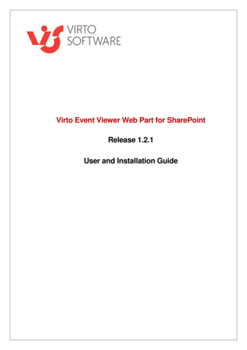
Add a Third-Party Controller to GVE1. Click System Menu (1) on the navigation bar.2. Click the Controller Manager icon (see the image to the right).3. Select the 3rd Party Controllers tab (2).Figure 7.Third-Party Controllers Tab4. Click Add New Controller (3).The Add New Controller dialog box opens:Figure 8.Add New Controller Dialog Box5. Enter the required information about the controller. Some fields (Model and Firmware)are optional. Required fields are: Room — Select a room from the drop-down menu. Only GVE rooms are in this list. Name — Enter a name that distinguishes the controller from other devices or itemson the network. Use only upper or lower case letters or numbers (no hyphens orother special characters). Time Zone — The time zone of the controller. GVE uses the time zone and DSTmode to calculate the local time of the controller. By default, this is set to the sametime zone as the local server. DST Mode — The Daylight Savings Time mode of the controller MAC Address — Media Access Control. It is a hex-based number that uniquelyidentifies hardware devices that connect to a network.GlobalViewer Enterprise Requirements and Setup7
Telnet Port — By default this is 23. HTTP Port — By default this is 80. DHCP — Dynamic Host Configuration Protocol. If this box is checked, the IPAddress, Subnet Mask, and Gateway are automatically assigned by the DHCPserver and cannot be edited in this dialog box. IP Address — Required if DHCP is disabled. A unique 32-bit binary number(12-digit decimal number: xxx.xxx.xxx.xxx) that identifies each sender andreceiver of information connected to a LAN, WAN, or the Internet. IP address canbe static or dynamic. Host Name — Required if DHCP is enabled. It identifies a particular host inelectronic communication. While same-domain connections are possible,cross-domain connections are not. Subnet Mask — Required if you are entering an IP address. It defines theboundaries of an IP subnet. Devices on a subnet share contiguous ranges of IPaddresses. Gateway — Required if you are entering an IP address. It is a device thatinterconnects networks with different, incompatible communication protocols.Refer to the glossary in the GlobalViewer Enterprise Help File for information about otherfields.6. If you have created asset tags (see the GlobalViewer Enterprise Help File), they are listedin the Asset Tags Info panel. You can assign a value to any appropriate tag.7. Click Add.The controller is now listed in the 3rd Party Controllers tab.Figure 9.New Controller AddedNOTE: Click on the delete icon ( ) to delete a controller. Click on the Edit icon (to edit the controller properties.GlobalViewer Enterprise Requirements and Setup)8
Add Attached or Controlled Devices1. Right-click in the row containing the controller you wish to add. A popup menu opens.Figure 10.Controller Popup2. Click Add Device.The Add Device box opens:Figure 11.Add Device Dialog Box3. Enter as much information as possible. The Controller Web Page field andBi‑directional check box are optional.NOTE: GlobalViewer Enterprise can support bidirectional and unidirectional devices.If the device is unidirectional, no status changes are sent to GlobalViewerEnterprise.Room can be selected from the drop-down menu. By default it is the same as controller.The required fields are: Device ID — User-defined ID associated with the added device.NOTES: The ID entered in this field must match the ID used within the third-partycode for the device. The ID cannot be 0 (the controller ID is always 0). Each device associated with a controller must have a unique ID. Anexception appears if an ID is repeated. In a system with multiple controllers, devices can only have the same IDwhen they are associated with different controllers. Device Name — Name used to identify the device in GlobalViewer Enterprise. Device Type — Select a device type from the drop-down menu.GlobalViewer Enterprise Requirements and Setup9
Manufacturer — Name of the device manufacturer that you can enter or selectfrom the drop-down list. Model — Device model name that you can enter or select from the drop-down list. Max Lamp Hours — This is required if the device type is a video projector. It is themaximum number of lamp hours for the projector.4. If you have created asset tags (see the GlobalViewer Enterprise Help File), they are listedin the Asset Tag section. You can assign a value to any appropriate tag.5. Click Add.6. Repeat steps 1 through 5 to add more devices.Click next to the controller to display a list of devices associated with that controller.Add Input SourcesIn order to track input sources usage, you will need to verify that the input sources havebeen added to the GVE system.1. Select the System Menu from the main menu bar (1).2. Click the Consolidate Input Sources icon (see the figure to the right).The Consolidate All Input Sources window opens:Figure 12.Consolidate All Input Sources Window3. Check whether the input source is listed in the table.4. If not, add the desired input source to GVE from this page:a. Click Add/Modify/Delete Input Sources (figure 12, 2).GlobalViewer Enterprise Requirements and Setup10
The Input Sources dialog opens:Figure 13. Input Sources Dialogb. Enter the Input Source name and click Add New (figure 13, 1).c. Click the exit icon in the top right corner (2).Add Device StatusesGVE provides users with a set of default statuses. If you need one or more additionalstatuses, you must add them as follows:1. Select the System Menu from the main menu bar (1).2. Click the Manage Device Statuses icon (see the figure to the right).The Device Status Manager window opens:Figure 14.Device Status Manager Window3. Select the 3 Party Device Statuses tab (2).rdGlobalViewer Enterprise Requirements and Setup11
4. Add the required 3rd Party device status. You must have one of the followingcombinations: Normal and Error Normal and Warning Normal, Error, and Warning5. Keep a record of the Device Status ID for programming purposes.Develop Controller CodeDevelop third-party code based on this protocol. This user-developed code maintainsfunctionality between the controller, any attached devices, and GlobalViewer Enterprise.To develop controller code refer to the specific topics in the following Communicationsections: Sequence number (see page 14) discusses GlobalViewer Enterprise full updaterequests with regard to messages that are lost or out of order. Full update (see page 23) discusses requests for full update, beginning with theinitial startup of the controller. Status data (see page 15) discusses how a power status change is accompaniedby a source status and vice versa. These details are necessary for GlobalViewerEnterprise reports to run properly because the available reports contain informationregarding lamp hours, usage, and so on. Support (see page 25) discusses changes requiring modification to the third-partycontroller code.GlobalViewer Enterprise Requirements and Setup12
CommunicationOverviewThis section discusses the communication between controllers and GlobalViewer Enterprise.Topics that are covered include: Communication Overview Security Message Packet Structure Commands Supported TableCommunication Overview GVE uses the IP address and TCP port entered by the user in the Add aProgrammable Controller wizard for communication. GVE opens a basic TCP socket connection on the port entered by the user to issuecommands to the programmable controller. For information about the command strings and their format, see Message PacketStructure on the next page.Any data or commands issued to the controller that do not follow this format areconsidered external data. GVE uses messages in UDP packets sent from a primary controller to collect statusinformation about devices managed by the controller. Messages are sent from thecontroller when there is a change to a status that is of interest to the server. If there is no controller or device status change, a heartbeat message packet is sentevery 20 seconds to ensure the controller is online. GVE does not perform any security (password) checks when a third-party controller isadded manually to the system. This facilitates the offline addition of controllers to GVE. GVE does not perform any security (password) checks while issuing commands to thethird-party controller. This is to avoid saving passwords in the GVE database. All security checks to validate the authenticity of the issuer of commands are theresponsibility of the third-party controller programmer. The third-party controller codeshould use some logic to ensure that the commands are being sent by GVE.SecurityGlobalViewer Enterprise Communication Overview13
Message Packet StructureThe following is the format of the third-party controller to GVE UDP packet:ENTR PrimaryControllerMACAddressNoDashes SequenceNumber [DeviceId aCmdID aCmdValue][SecondaryControllerMAC aCmdID aCmdValue] ETX The message packet is split into two parts: Fixed-length header that GVE uses to identify the controller Variable-length data section (body) containing zero or more device status sections (seeStatus data on page 15 and Heartbeat on page 22)The message packet ends with the ETX (0x03) character. All message packets are sent toUDP port 5555 at the server.HeaderThe header portion of the packet is further divided into three fixed-length fields.HeaderIDMAC AddressSequence Number4 bytes12 bytes3 bytesIDThese 4 bytes are fixed as ENTR.MAC addressThe MAC address is the ASCII-encoded hexadecimal representation of the controller MACaddress, without hyphens.For example, the MAC address 00-05-A6-00-C1-94 appears as 0005A600C194.NOTE: The MAC address is included in the header, allowing GVE to authenticate thecontroller. Unrecognized MAC addresses should be ignored. This ensures GVEreceives a message from the appropriate controller and sends a message to theintended controller.Sequence numberNOTES: The sequence number is in ASCII and is automatically generated by the controller,in sequence, from 000 to 255 and is padded with leading zeroes to three places. The sequence number increases by an increment of 1 on the controller aftersending each message. A message with sequence number 255 is followed by a message with sequencenumber 000. There are no reserved sequence numbers.GlobalViewer Enterprise uses this field to determine if there have been any missedmessages. If messages are lost or arrive out of order, GlobalViewer Enterprise requestsa full update from the controller. The threshold for requesting a full update is one missedmessage.GlobalViewer Enterprise Communication Overview14
BodyThis portion of the message packet contains status information and device information for adevice.Status dataStatus change notifications for each device are grouped inside square brackets. This is thesame as communication with IP Link, IP Link Pro, and third party controllers. The format is:[Device 1 data] [Device 2 data].[Device n data]A device data section contains a device ID and at least one status item. The device IDappears first in this section followed by the status item. The format is:[device id command id value].A message does not contain a section for a device unless there is a change to report for it.Device IDNOTES: The device ID for the controller is always 0. The ID for managed devices is determined after adding a device as shown in Adda Third-Party Controller to GVE (see page 7). See the Commands Supported Table, starting on page 17, for informationregarding the command IDs and values.When the data packets or full update packets have statuses for devices, the Device ID is thevalue entered in the Add A New Device wizard (see Add Attached or Controlled Deviceson page 9).Status itemThis is the key-value pair, indicating the numeric command ID and the value to which thecommand is changed. An equal sign ( ) appears between the command ID and value.Status items are separated with a tilde character (ASCII 0x7E). The format for one devicewith one command is:[device id command id value]For example, a complete device data section indicating a change in the lamp hours of aprojector (device ID 1) to 1000 appears as follows:[1 20 1000]The device data between brackets can also have multiple command IDs. The messagestructure for one device with two commands is:[device id command id value command id value]For example, a complete device data section indicating a change in the lamp hours of aprojector (device ID 1) to 1000 and a change in device status to a lamp warning level onthe same device appears as follows:[1 20 1000 22 0603]If a device has more than two commands, this structure is still applicable. A tilde ( )separates each command ID and its respective value.GlobalViewer Enterprise Communication Overview15
Multiple devices can be updated in GlobalViewer Enterprise within the same message. Themessage for two devices with two commands is:[device id command id value command id value][device id command id value command id value]Depending on the devices, multiple status updates can occur simultaneously. In thisexample, status updates occur for both a laptop (device ID 1) and a second source (deviceID 2). The updates include power status and source status for each device. The statusstring appears as follows:[1 17 1 18 Laptop][2 17 1 18 S-Video]Each device ID refers to a new device and the above format is still applicable if there aremore than two devices.A message from the controller appears with a format similar to messages from a device. Thecontroller ID is always 0.For example, a 3 C increase in the temperature of a controller (device ID 0) to 46 Cappears as follows:[0 28 46C] ETX End of transmission characterEvery UDP status packet ends with the ETX (0x03) character.See the Commands Supported Table starting on the next page for information regardingthe command IDs and values within this example.Character EscapingCertain characters must be escaped when they appear in the “value” section of the data.The escape sequence is a backslash ( \ ) followed by the ASCII-encoded hexadecimal valueof the encoded character. Essentially, these escape sequences appear in place of theirrespective characters if used in the “value” section but are read as the characters.Characters to be EscapedCharacterEscape Sequence \7E \3D\\5C[\5B]\5DFor example, if command ID 5 is used for a device named “[Apple],” the framing charactersof the name are escaped.It appears as this section marked in bold:ENTR0005A600C194000[0 5 \5BApple\5D] ETX GlobalViewer Enterprise Communication Overview16
Commands Supported TableNOTE: The controller or controlled devices may not support all of these command orstatus items. If this is the case, disregard that particular item.Controller MessagesNameCommandIDValueStatusControl(to GVE) (from GVE)NotesUpdateRequest00 StopNoYesFirmwareVersion1 string YesNoString similar toDHCP20 Off1 OnYesNoIf DHCP is on, thenGVE uses the hostname to communicatewith the controller.Subnet Mask3 string YesNoString similar toNoString similar toWhile same-domainconnections arepossible, cross-domainconnections are not.communication1 Full Update/ResumeGatewayAddress4 string YesHost Name5 string YesNoTelnet Port60-65535YesNoHTTP Port70-65535YesNoTime Zone8 signed ASCIIdigits YesNo1.12.0010255.255.0.010.0.100.1String appears in GMTformat:For the Pacific timezone, it appears as“-08:00.”For the Tokyo timezone, it appears as“09.00“GVE calculates thelocal time for thecontroller based on thetime zone and the DSTmode.DST Mode90 Off/Ignore1 USA2 Europe3 BrazilYesNoE-mail Server10 string YesNoIP address of theserver used to sende-mails.E-mailDomain11 string YesNoSimilar to extron.comE-mail UserName12 string YesNoThe e-mail accountuser name is usedif the e-mail serverrequires authentication.GlobalViewer Enterprise Communication Overview17
Controller MessagesNameCommandIDValueStatusControl(to GVE) (from GVE)E-mailPassword130 Unset1 SetYesNoPower17-1 Unknown0 Off1 On2 Cool Down3 Warm UpYesYesNotesOnly “On” and “Off”can be used ascommands.Unknown: thecontroller has not yetdetermined the powerstate.Relay Open24# Relay#NoYesRelay Close25# Relay#NoYesYesRelay Pulse26# Relay#NoRelay Toggle27# Relay#NoYesControllerTemperature28 Temp F or C YesNoMaximum relay numberdepends on theproduct.Pulse is always 500 msLimits depend on thedevice.Status change appearsif there is a temperaturechange of 3 C or 5 FNOTE: When a power command is sent to a controller, a second message must besent for the same power command for an attached device. For instance, when aPower Off action is desired, a Power Off must be scheduled for the controllerand a second Power Off action must be scheduled for any projectors or displaysconnected to the controller. Powering off each device within a specified locationensures a full power off.GlobalViewer Enterprise Communication Overview18
Projector and display devices (LCD, plasma, and so on)Device Messag
A new location icon appears in the tree with the text Location highlighted. Figure 3. Add New Location 3. Replace Location with the name of the new location. To rename a location, double‑click the location name to highlight it and enter the new name. To move a location, drag and drop it in a new position within the location tree. Add a GVE Room


![Radiant Dicom Viewer Cracked Rib [REPACK]](/img/39/evemelt.jpg)