Transcription
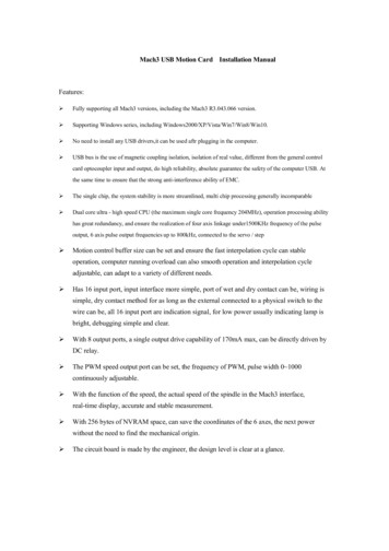
Mach3 TutorialSetting up a basic three axis milling machine.Based on Mach3 2.0Purpose.The purpose of this tutorial is to help and to guide the user to, step by step, set up and tune theMach3 CNC controller application for use on a basic 3 axis milling machine. We will go thruthe steps of setting up the emergency stop, the charge pump circuit the main axis motors, thespindle and coolant as well as the home switches and the software based over-travel limits.The tutorial is based on the Mach3 v2.0 series and is meant to be used as complement to theexisting Using Mach 3 Mill manual.Let’s get started.When first installing the software it’s vital to reboot the computer as the installer prompts. Ifyou don’t do this the software will not work and you will have to manually remove the Mach3driver from the system. After installing the software and rebooting the computer you shouldhave four icons on your desktop. These icons all launches Mach3 but it also loads a differentset of screens depending on what kind of machine it is we are running. Since this tutorial isaimed at getting a milling machine up and running we’ll start the software with the onelabelled Mach3Mill. When the software is started you may be presented with the followingdialog but if not don’t worry.Figure 1: Hardware plugin.Since we are going to use the computers printer port as the electrical interface between thecomputer and our machine we make sure that the Normal Printer Port Operation mode isselected and since we don’t want to tell Mach3 this information each time we start thesoftware we put a checkmark in the box next to Don’t mask me this again and then click OK.1
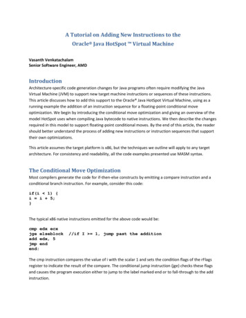
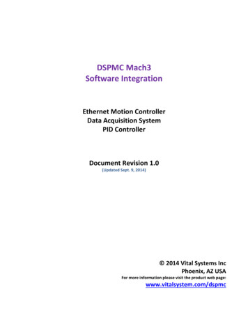
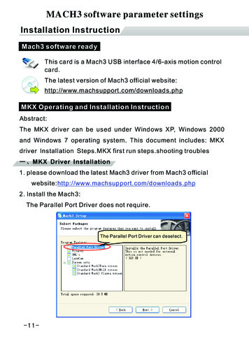
Metric or imperial.The next thing we need to do is to select the native units of choice. To do this we go to theConfig menu and click Select Native Units and select either inches or mm and click OK. SinceI’m a metric guy I choose mm.Figure 2: Default UnitsPlease note that, as the message says before you get to the windows in figure 2, this selectionis not for switching the actual displayed coordinates between inches and mm nor is it meant toswitch between running part programs written in inches or mm. It is ONLY for setup andtuning of the motors.The hardware interface and connections.Now we need to do is tell Mach3 how many parallel ports and at which addresses they arelocated. If the port is onboard your computers motherboard the standard address is 0x378. Butother addresses are sometimes used as well. We tell Mach3 this information by selectingPorts and Pins under the Config Menu.Figure 3: Engine Configuration, Ports & Pins2
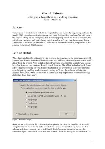
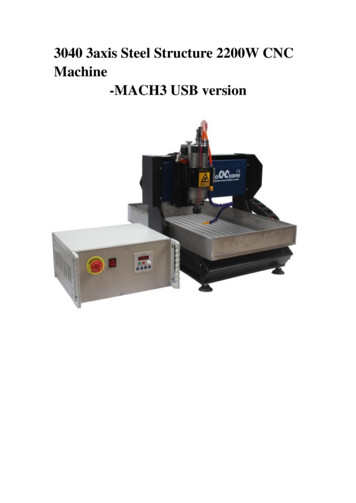
First check that the address of Port#1 corresponds to the actual address of your printer portand that it is enabled. 0x378 is the address most onboard parallel ports use. Since we won’t beusing a second port here we make sure that Port#2 is disabled. (No checkmark in the PortEnabled box under Port#2).Next thing to do is to select our Kernel speed. This is the frequency at which the Mach3 driveroperates and is also the maximum frequency the software will output to your motor drives.We will use 25000Hz here. Also make sure that none of the options on the right side isenabled and then click Apply.Next in line is the Motor Outputs tab. This is where we tell Mach3 how many motors we wantto control and to which pins in our printer port the each motor driver is connected. In this caseit’s three axis, X, Y and Z so we enable those three by making sure that there is a greencheckmark in the first column of those axis.The second column sets the pin to which the step input on our motor drive is connected. Inthis case the X axis drive step input is connected to pin 2, Y to pin 4 and Z to pin 6. The thirdcolumn is just like the second but for the drives direction inputs, wired to 3, 5 and 7 on thismachine. The actual pin out of your machine may be different. If you have wired it yourselfyou probably know the pin out and if you bought the machine and/or driver box pleaseconsult the documentation for that particular machine or check with the hardwaremanufacturer.The setting of the forth and fifth column depends on how the drives are built and how wehave them wired. The most common drives uses optically isolated inputs and are usuallysupplied with a constant 5V DC from the PC. The drives step and direction inputs are thenwired to the computers parallel port which internally switches the pin to ground making thecurrent flow thru the LED in the drives opto isolator which in turn makes the drive move themotor one step. This makes our step-line active low – that is it’s ‘on’ when the output is low.Makes any sense?Figure 4: Engine Configuration, Motor Outputs tab.OK, that was the physical connection for the motors. Next thing to take care of would be toset how many steps per unit we have and then go on to actually tune the motors. But beforewe do that we need to tell the system about one more important thing.3
The Emergency Stop button.Any decent machine tool should have an Emergency Stop button that, in the safest possibleway, halts all machine movement and prevents damage to the operator in the first place and/orthe machine – so will this one. This tutorial will not go into the actual hardware design of aproper E-stop system but will focus on getting Mach3 to understand that the big red buttonhas been pushed. The various input signals to Mach3 are setup on the Input Signals tab underPorts and Pins in the Config menu:Figure 5: Engine Configuration, Input Signals tab.About halfway down the list we should be able to find the EStop signal, make sure it isenabled. In this case the hardware is wired in such way that the input is brought high when theswitch is pushed so the Active Low setting should not be active. In case you don’t have an EStop switch you will probably have to enable the Active Low option to be able to take thesoftware out of E-stop mode but more on that later. As the E-Stop is the only input we’ll usefor now we make sure that none of the other inputs are enabled. Click OK to save the settingsand close the dialog.Now lets se if we can get the system out of E-Stop mode. Make sure your hardware E-stopbutton is not pressed then, on the main screen click the big red button labelled Reset.Hopefully the blinking frame around the button will stop blinking and turn in to a nice solidgreen. If it doesn’t turn green go back to the dialog in figure 5 and reverse the Active Lowsetting for the E-stop input as described above and try again.With the E-stop input out of the way and working we’ll move on.4
Motor Tuning:Finally we’ll get to actually spin some motors. The first thing in the tuning process is tocalculate how many steps per unit of travel we have. This depends on a few things:In case of a step motor: The amount of steps per revolution, most commonly 200. The step resolution of the motor drive, full step, half step, 5, 10, 100 micro steps etc.In case of a servo motor. The amount of quadrature counts produced by the encoder on the motor The ‘encoder mode’ of the motor drive. 1, 2 or 4 encoder counts.In both the above cases: The reduction ratio between the motor shaft and lead screw. And finally, the thread pitch of the screw. (How far the table moves with each rotationof the screw).It should be noted that other actuating systems could be used like belts, rack & pinions etc buthere we will use a lead or ball screw as the basis for our calculation. We will do one metricand one imperial example.The metric one:Let’s assume we have a standard step motor with 200 steps per rev. This motor is driven by adriver set to 5 micro steps per full step. A Gecko G210 from Geckodrive for example. Themotor is directly coupled to the lead screw which has a pitch of 5mm per revolution. Thatmeans the axis will move 5mm for each revolution of the screw.So we’ll take the motors 200 steps multiply that by the drives 5 micro step. (200 X 5 1000)The drive needs 1000 pulses (or steps) to turn the screw one revolution thus making the axismove 5mm. So now we take those 1000 steps and divide by the pitch of the screw, which is 5.(1000 / 5 200). In other words we need 200 steps to move one unit or mm.The imperial one:Let’s assume a DC-servo with a 500 line encoder and a drive that uses all four quadraturecounts of the encoder effectively making it a 2000 counts per rev motor/encoder combo. Let’salso assume we have 3:1 belt reduction driving our screw which has a 5TPI pitch.The drive needs 2000 pulses, or steps, to turn the motor one revolution. But since we have the3 to 1 belt reduction between the motor and the screw we need to multiply the 2000 by 3 tomake the screw turn one revolution.6000 steps will make the screw turn one revolution, making the axis move 1/5 of an inch. Tomake the axis move one inch we need the screw to make five revolutions so 6000 X 5 30.000 steps per unit or inch.In reality a steps per unit value as high as 30.000 will greatly reduce the speed at which themachine can move.5
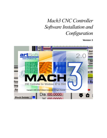
So now we have determined how many steps the computer needs to send out to the drives inorder to move the machine one of our selected units, be it inch or mm. Let’s tell Mach3 whatwe’ve come up with. In the Config menu, we select Motor Tuning and the following dialogshould present itself:Figure 6: Motor Tuning and Setup.The first thing to do is to enter the steps per unit we found in our calculation. We do this inthe lower left corner. We’ll use the metric calculations above as base for this setup so 200steps per unit it is. Now comes the fun part. By dragging the sliders to the right and belowwe’ll adjust the speed and the acceleration of the motor. This can of course be calculatedbased on motor torque, machine inertia, mass etc but is mostly done on a trial and error basis.Start by moving the velocity slider up a bit and then press the up or down arrow key on thekeyboard. The motor should now spin, if not make sure that the system is enabled and not inE-stop mode.By adjusting the Velocity and Accel sliders try to find a speed and acceleration that feelscomfortable and where the motor run smoothly without any tendency to jerk, halt, or loosesteps. Then, and this is important, click Save Axis Settings. Now click the Y Axis button andrepeat the process for that axis and then do the same for the Z axis. Don’t forget to press SaveAxis Settings before switching axis. If you don’t your setting will be lost.Please note: It’s in perfect order to have a different step per unit setting as well as Velocityand Accel values for each axis. Mach3 will keep them I perfect sync either way. You mayeven have fractional steps per unit set for one or more axis, for example 201.3 if that is whatyou need.If you can’t seem to get the motors to run smoothly there are a few things to check, first theeasy one: Some motor drives need to have a longer step pulse and this can be set by changingthe Step Pulse setting. See the manual for your particular drive.6
The other thing to check is the voltage at parallel port pins. Most drives inputs are opticallyisolated and designed to accept a 5V input. Some of the newer PC motherboards, especiallylaptops, only outputs about 3.3V and this can be problem for some drives. To address this, theeasiest way is to either fit a PCI LPT-port card in the PC or to get one of the various breakoutboards available that supports boosting the voltage to 5V.OK, to put the tuning to the test lets go to the MDI screen and make the machine do somemoves. Click the MDI button or press ALT-2 and then click the MDI input or hit enter toenable it for input. Now type something like G0 X10 Y10 Z10 and press enter. The machineshould move all three axis from its current position to X10 Y10 Z10. The actual values usedfor this test depends of the size of your machine but you’ll get the idea. Try a couple ofdifferent moves back and forth to make sure the motor tuning is OK. If one or more axis stallsor looses steps the tuning needs to tweaked a bit more.Figure 7: The MDI-screen.7
Making sure the machine and DRO’s moves in harmony.On a standard three axis milling machine the X axis moves from left to right, the Y axismoves towards and away from you and the Z moves up and down. In the following section allmovement is considered to be of the actual tool – that is the tool moves to the right eventhough it’s actually the table that moves to the left.Go back to the Program Run screen by pressing the Program Run button or hitting ALT-1.Make sure the LED around the Jog ON/OFF button is green, if not press that button to enablethe machine to be jogged. (The button is located in the lower middle section of the screen).Now hit the TAB-key on the keyboard to bring out the Jog-control screen. It should come outfrom the right side of your screen. If you can’t see all the controls just grab the grey line anddrag it out as far as you wish. Now we need to tell Mach3 at what speed we want it to jog andwe do that by entering a jog rate in the DRO labelled Slow Jog Rate on the jog control screen.Let’s start slow with something like 10%. Click the DRO, type in the value of your choice andhit enter.Figure 8: The Program Run screen, with jog-panel fly-out.Now press the right arrow key on the keyboard. If all is well the X-axis DRO should count upand the tool on the machine should move in the positive direction (to the right) (table movesfrom right to left). If the DRO counts up but the tool moves in negative direction we need toreverse the motor direction. We do this by reversing the Dir Low Active setting in Ports andPins, Motor Outputs. If the tool moves to the right but the DRO counts down we have tochange the hotkey for the axis jog. This is done by selecting System Hotkeys in the ConfigMenu. When the X-axis is OK repeat the steps for the Y and Z axis.8
The Y axis DRO should count up and tool should move away from you (table movingtowards you when standing in front of the machine) when pressing the up arrow key.The Z axis i
Mach3 CNC controller application for use on a basic 3 axis milling machine. We will go thru the steps of setting up the emergency stop, the charge pump circuit the main axis motors, the spindle and coolant as well as the home switches and the software based over-travel limits. The tutorial is based on the Mach3 v2.0 series and is meant to be used as complement to the existing Using Mach 3 Mill .


![Unreal Engine 4 Tutorial Blueprint Tutorial [1] Basic .](/img/5/ue4-blueprints-tutorial-2018.jpg)