Transcription
SPECIFICATIONS FORSPIRAL PIPE AND FITTINGSMINNEAPOLIS, MN5850 MainMain StreetStr eet N.E.Minneapolis, MN 55432LOCALLY CALL: 763-572-0000TOLL FREE: 1-800-328-1966FAX: 763-572-1100ROCKFORD, IL5601 Sandy Hollow RoadRockford, IL 61109LOCALLY CALL: 815-874-4600TOLL FREE: 1-866-504-4600FAX: 815-874-9979
Corporate HeadquartersSHEET METAL CONNECTORS, INC.5850 MAIN STREET N.E. MINNEAPOLIS, MINNESOTA 55432Toll Free: 800-328-1966 Local: 763-572-0000 Fax: 763-572-1100www.smcduct.comManufacturing Facilities5850 Main Street N.E.Minneapolis, MN 55432LOCAL: 763-572-0000TOLL FREE: 1-800-328-1966FAX: 763-572-11005601 Sandy Hollow RoadRockford, IL 61109LOCAL: 815-874-4600TOLL FREE: 1-866-504-4600FAX: 815-874-9979Sheet Metal Connectors, Inc. is proud to be a member or affiliatedwith the following associations;Sheet Metal Workers’ International AssociationWashington, DCSheet Metal Air Conditioning Contractors’National AssociationChantilly, VASPIDASpiral Duct Manufacturers AssociationIrmo, SCSMACNA Testing & Research InstituteChantilly, VA
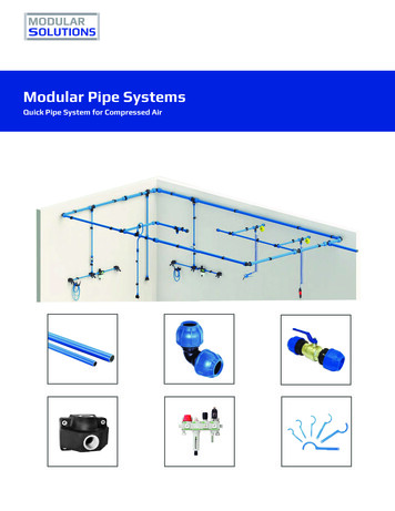
1Single-Wall Spiral Pipe & FittingsSheet Metal Connectors, Inc. (SMC) Single Wall Pipe and Fittingswith Complete Seal, E-Z Flange and Barrel Clamp or Standard Slip ConnectionSingle-Wall Spiral PipeSheet Metal Connectors, Inc. spiral pipe is formed from a coil ofmetal into a rigid steel tube with a 4-ply spiral lockseam. It hasa smooth interior for low friction loss with the grooved seamentirely on the outside. This pipe has a resistance to crushing5"approximately 2 1/2 times that of longitudinal lockseamorwelded pipe. Optional corrugations are available which increasethe rigidity of the pipe by approximately 300%. Pipe sections canbe joined together by an Complete Seal Spiral Pipe Connector,5"5" Clamp,E-Z Flangewith Barrel Clamp, E-Z Flange Jr. with BarrelStandard Spiral Pipe Connector, or Companion Angle Rings.5”5"Lateral section of 4-ply pressure-proof spiral seam.5”5"Lateral section of grooved seam with optional corrugated grooves.55”Optional culvert groove.Single-Wall �� - 96”Galvanized26 - 14 gaugeA-653G60-G901’ – 20’, 10’ Standard3” - 96”Paint Grip24 - 18 gaugeA-653A601’ – 20’, 10’ Standard3” - 96”PVS*24 - 16 gaugeA-6534 x 1, 4 x 41’ – 20’, 10’ Standard3” - 60”**Aluminum.032 - .063B-3163003 H-141’ – 20’, 10’ Standard3” - 60”**Stainless Steel24 - 18 gaugeA-240304 or 3161’ – 20’, 10’ Standard*PVS specification book available** Call factory for sizes over 60” in diameter.Single-Wall FittingsElbow Lock SeamSMC spiral fittings are manufactured with an elbow lock seam, lapseam (i.e. stitch weld, riveted, tack weld or solid weld), standingseam or butt weld seam. These may be with or without ductsealant.Riveted Lap SeamAll fittings can be manufactured with: Complete Seal Spiral Pipe System – 6” to 24” Diameter (even sizes)E-Z Flange Jr. with Barrel Clamp – 6” to 24” DiameterE-Z Flange with Barrel Clamp – 26” to 96” DiameterStandard Spiral Pipe EndCompanion Angle RingStanding SeamButt Weld SeamStich WeldNote: SMACNA Testing and Research Instituteverified that Sheet Metal Connectors, Inc.shop standards comply with the 2005-3rd editionof the SMACNA HVAC Duct Construction Standards.May 2013
2Single-Wall ConnectorsComplete Seal Fittings 6” to 24” DiameterComplete Seal fittings are manufactured from galvanized steelmeeting spec ASTM A-653 (Lockforming quality). They featurea double legged EPDM gasket which creates a virtually airtightconnection when slipped into spiral pipe. The gasketis mechanically attached to the fitting with a 180degree hemmed edge. This hem gives added rigidity to thefittings, ensures that the gasket will never slip out of place andmakes a safe rounded edge for the installer.*Complete Seal is currently available on Galvanized Fittings only.E-Z Flange with Barrel Clamp 26” to 96” DiameterThe E-Z flange with barrel clamp can be factory installedor shipped loose for field installation. A set consists of twoE-Z flanges and one barrel clamp. For field installation theinstaller attaches the E-Z flange to the pipe and fittings. Nextthe installer applies the gasket to one flange, mates the twoflanges together and attaches the barrel clamp. Sheet MetalConnectors can also install E-Z flanges. Flanges are spotwelded and internally sealed on all ends of the spiral pipe andfittings.E-Z Flange Jr. with Barrel Clamp 6” to 24” DiameterThe E-Z flange jr. is a 5/8” flange turned out 90 on each endof the spiral pipe and fittings. The installer applies a gasket onone flange, mates the two flanges together, and attaches thebarrel clamp. For field cuts a 5/8” flanged sleeve is available.Trim the spiral pipe to the measured length and attach thesleeve.Standard Spiral Pipe ConnectorPipe to Pipe connections are made by using a fitting sizecoupling that slips inside the mating pipe sections. A stopbead runs around the middle of the coupling to center thecoupling in the connection. Secure the connection byinstalling sheet metal screws through the outer shell of theduct, 1/2 inch from the stop bead.Companion Angle Rings Pressed and RolledCompanion angle rings are for end connections whenever a smoothinterior surface or intermediate stiffening is required. Rings aremanufactured from mild steel. Companion angle rings can befactory installed or shipped loose. Companion angle rings can beattached by solid weld, tack weld, or van stone connection.See companion angle ring size chart on page 20.
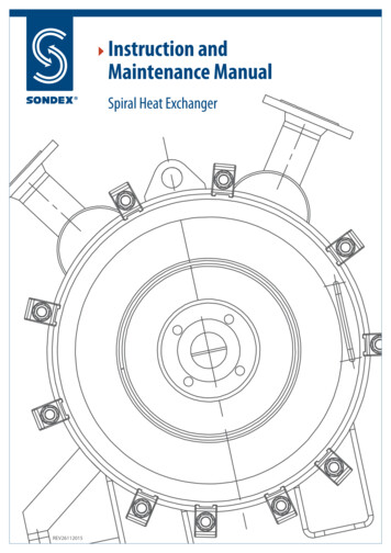
Positive PressureWeight and Gauge 8.519.520.521.522.523.424.53Bursting Pressure various gauges of spiral ndard gauges in boxed area, weights may vary slightly.CLOSE CELL NEOPRENE GASKETNeoprene1/4” x 1/2”(50’ rolls - 1500’ per box)E-Z Flange Jr.Neoprene1/4” x 3/4”(50’ rolls - 1500’ per box)E-Z Flange & 8578736865595551474441391 PSI 27.678 H20All tube diameters in inches. All pressure in PSI.Internal PressureCollapsing Pressure various gauges of spiral 511.04.39.89.0.036 PSI 1 inch 985.872.062.253.947.241.337.434.624.8Internal negative pressure in inches of water.These tables are given only as a courtesy. Sheet Metal Connectors is not responsible for any results listed on these charts.
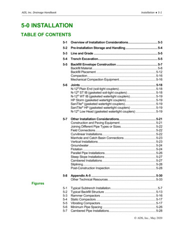
4Two Piece Pressed Solid Welded ElbowsCenterline ThroatRadius �12”14”4 1/2”6”7 1/2”9”10 1/2”12”13 1/2”15”18”21”4 1/2”6”7 1/2”9”10 1/2”12”13 1/2”15”18”21”All Fittings are 1.75”from Bead to End of Fitting.Pressed elbows and angles are resistance welded with copper on both the heel and throat. All pressed fittings are manufacturedfrom extra deep drawing steel (EDDS) in accordance with ASTM-A653. Pressed fittings are precision drawn, tolerances must bewithin or - .002 thickness to assure a quality product at all times. All pressed fittings are made of 24 Ga. or 22 Ga. Galvanizedmaterial with a G60 or better coating thickness and are chemically treated to retard white rust.Standing Seam Elbows & AnglesStanding Seam Elbows and AnglesStanding Seam fittings work well for medium pressure applicationsand offer an alternative to welded elbows and angles. These areavailable from 8” through 60” diameters and fabricated as heavy as16 gauge. Other diameters and throat radiuses are available.* 42” and larger diameter 90 degree elbows are fabricated using two45 degree angles connected with an E-Z Flange and Barrel Clampunless otherwise specified.Standard Throats8” thru 18”20” thru 40”42” thru 60” *8” Throat10” Throat20” ThroatAll Fittings are 1.75”from Bead to End of Fitting.Full Sweep Standing Seam Elbows8”-30” will be a 5 gore one piece standard throat construction.32” and larger in diameter 90 degree full sweep (1.5 x CL) elbowsare fabricated using two 45 degree angles connected with an E-Zflange and barrel clamp unless otherwise specified.
5Adjustable Elbows & Angles90 Throat and Gauge ��1”1 1/2”1 1/2”1 1/2”1 1/2”2”2”2”3”2 1/2”1”1 1/2”1 1/2”1 1/2”1 1/2”2”2”2”3”2 1/2”N/A1 1/2”1 1/2”1 1/2”1 1/2”2”2”2”3”2 �5”5”5”45 Throat and Gauge ChartDDFull sweep elbows and angles are availableup to 16” ��N/AN/AN/AN/A5”5”5”5”Welded Gored Elbows & AnglesStandard Elbows and Angles are fabricated from20 gauge galvanized material. Other diameters,throat radiuses and gauges are available, pleaseconsult factory.52” and larger in diameter 90 degree full sweep(1.5 x CL) elbows are fabricated using two 45degree angles connected with an E-Z flange andbarrel clamp unless otherwise specified.
690 TeeDimensions to be listed as follows: A, B, CL “C” 4”All Fittings are 1.75”from Bead to End of Fitting.Teewith ReducerDimensions to be listed as follows: A, B, CL “C” 4”L.R.: Refer to page 9All Fittings are 1.75”from Bead to End of Fitting.CrossDimensions to be listed as follows: A, B, C, DL Largest of “C” or “D” 4”All Fittings are 1.75”from Bead to End of Fitting.Crosswith ReducerDimensions to be listed as follows: A, B, C, DL Largest of “C” or “D” 4”L.R.: Refer to page 9All Fittings are 1.75”from Bead to End of Fitting.
7ConicalTeeDimensions to be listed as follows: A, B, CL C 5”All Fittings are 1.75”from Bead to End of Fitting.Conical Teewith ReducerDimensions to be listed as follows: A, B, CL C 5”L.R.: Refer to page 9All Fittings are 1.75”from Bead to End of Fitting.ConicalCrossDimensions to be listed as follows: A, B, C, DL Larger of “C” or “D” 5”All Fittings are 1.75”from Bead to End of Fitting.Conical Crosswith ReducerDimensions to be listed as follows: A, B, C, DL Larger of “C” or “D” 5”L.R.: Refer to page 9All Fittings are 1.75”from Bead to End of Fitting.
8LateralDimensions to be listed as follows: A, B, CL (1.414 x C) 4”All Fittings are 1.75”from Bead to End of Fitting.Lateralwith ReducerDimensions to be listed as follows: A, B, CL (1.414 x C) 4”L.R.: Refer to page 9All Fittings are 1.75”from Bead to End of Fitting.LateralCrossDimensions to be listed as follows: A, B, C, DL 1.414 x (Larger of “C” or “D”) 4”All Fittings are 1.75”from Bead to End of Fitting.LateralCross with ReducerDimensions to be listed as follows: A, B, C, DL 1.414 x (Larger of “C” or “D”) 4”L.R.: Refer to page 9All Fittings are 1.75”from Bead to End of Fitting.
9BullnoseTee (Bullhead)Dimensions to be listed as follows: A, B, CL.R.: Refer to page 9All Fittings are 1.75”from Bead to End of Fitting.Pairof Pants (Wye Branch)Dimensions to be listed as follows: A, B, CAll Fittings are 1.75”from Bead to End of Fitting.OffsetDimensions to be listed as follows: A, O, LAll Fittings are 1.75”from Bead to End of Fitting.LR Value for Tees and 528.2529.2531.2532.2533.25* Add 1.5” to LR Value for Diameters over 18”
1090 Swedged SaddleDimensions to be listed as follows: A on BAll Fittings are 1.75”from Bead to End of Fitting.45 Swedged SaddleDimensions to be listed as follows: A on BAll Fittings are 1.75”from Bead to End of Fitting.90 Full SaddleDimensions to be listed as follows: A on BAll Fittings are 1.75”from Bead to End of Fitting.45 Full SaddleDimensions to be listed as follows: A on BAll Fittings are 1.75”from Bead to End of Fitting.
1190 Conical Swedge SaddleDimensions to be listed as follows: A on BB A 1”All Fittings are 1.75”from Bead to End of Fitting.90 Shoe TapDimensions to be listed as follows: A on BC A 3”All Fittings are 1.75”from Bead to End of Fitting.RegisterTakeoffsDimensions to be listed as follows: A, B on C6"(Order Takeoffs by Register Size Only)BC1"AEndCap (Plug)Dimensions to be listed as follows:A, equal diameterAll Fittings are 1.75”from Bead to End of Fitting.Connector(Coupling)Dimensions to be listed as follows:A, equals diameterAAll Fittings are 1.75”from Bead to End of Fitting.3.5”1"
12Pressed FittingsAll stamped fittings are manufactured from extra deep drawing steel (EDDS) in accordance with ASTM–A653. This type of steel ismanufactured by domestic steel mills and has some unique qualities. Stamped fittings are precision drawn, tolerances must bewithin or - .002 thickness to assure a quality product at all times. All pressed fittings are made of 24 Ga. or 22 Ga. Galvanizedmaterial with a G60 or better coating thickness and is chemically treated to retard white rust.90 Saddle TapDimensions to be listed as follows: A on BRadiusAll Fittings are 1.75”from Bead to End of Fitting.ExistingPipe90 Saddle Tap W/DamperDimensions to be listed as follows: A on BAlso available with 2” Insulation ExtensionAll Fittings are 1.75”from Bead to End of Fitting.ConcentricReducerDimensions to be listed as follows: A, BAll Fittings are 1.75”from Bead to End of 1”1”1”1”1”1”1”1”1”1”1”1”2 3/4”2 3/4”2 3/4”2 3/4”2 3/4”3 1/4”3 1/4”3 1/4”3 1/4”3 1/4”3 1/4”3 1/4”3 1/4”3 1/4”3 1/4”3 1/4”3 1/4”3 1/4”3 1/4”3 5”6.5”6.5”ABOverall �10”12”14”12”14”16”6 3/4”8 1/2”6 3/4”8 1/2”6 3/4”8 1/2”6 3/4”10 1/28 1/26 3/4”10 1/28 1/26 3/4”
13ConcentricReducerDimensions to be listed as follows: A, BLR See ChartAll Fittings are 1.75”from Bead to End of Fitting.SizeReductionLR12&3456789101112131415 & 1617 & 521.522.525.528.529.531.532.533.5Eccentric ReducerDimensions to be listed as follows: A,BLR See ChartLRAAll Fittings are 1.75”from Bead to End of 51113.51618.52123.52628.53133.538.543.548.553.5
14High Efficiency Die Stamped Takeoff(Super HETO)SuperHetoOrder as follows: A DiameterPatent # US D571,908 SAOverallLength5”6”8”10”12”14”10 1/2”6 1/2”7”7”7”7”All Fittings are 1.75”from Bead to End of Fitting.SuperHeto with DamperOrder as follows: A ”6 1/2”10”7”10 3/4”7”7”7”All Fittings are 1.75”from Bead to End of Fitting.SuperHeto with 2” ExtensionOrder as follows: A ”6 1/2”10”7”10 3/4”7”7”7”All Fittings are 1.75”from Bead to End of Fitting.SuperHeto with 2” StandoffOrder as follows: A ”9”9”9”All Fittings are 1.75”from Bead to End of Fitting.
15Standoff CollarsE-ZTap Collars with 2” StandoffOrder as follows: A DiameterAlso available with 2” Insulation ExtensionAll Fittings are 1.75”from Bead to End of th6”8”10”12”9 1/4”9 1/4”9 1/4”9 1/4”AOverallLength16”18”20”14 1/4”15 1/2”15 1/2”ConicalE-Z Tap with 2” StandoffOrder as follows: A DiameterAlso available with 2” Insulation ExtensionHighEfficiency with 2” StandoffOrder as follows: A DiameterAlso available with 2” Insulation ExtensionAll Fittings are 1.75”from Bead to End of Fitting.
16E-ZTap CollarOrder as follows: A Diameter3”All Fittings are 1.75”from Bead to End of Fitting.E-ZTap Collar with DamperOrder as follows: A DiameterAlso Available with 2” Insulation Extension5”All Fittings are 1.75”from Bead to End of Fitting.E-ZTap Conical Takeoff CollarOrder as follows: A Diameter6.5”E-ZTap Conical AlsoTakeoffCollar with DamperOrder as follows: A DiameterAvailable with 2” Insulation Extension7”LENGTHCONE DIAMETERA
Damper SleevesComplete Seal Damper SleeveOrder as follows: A DiameterAlso available with 2” Insulation ExtensionAll Fittings are 1.75”from Bead to End of Fitting.Complete Seal Damper Sleeve with 2” StandoffOrder as follows: A DiameterAll Fittings are 1.75”from Bead to End of Fitting.Sleeve with 2” StandoffOrder as follows: A DiameterAlso available with 2” Insulation ��18”20”6 3/16”6 3/16”6 3/16”6 3/16”6 3/16”8”12”12”13”15”LengthA17
18NotchedCollarsOrder as follows: A DiameterNotchedCollars w/DampOrder as follows: A DiameterLengthLengthAAALength4” thru 20”2 3/4ALength4” thru 7”8”9”5 1/2”7 1/4”8 1/4”9 1/4”13 1/4”15 1/4”17 1/410” thru 12”14” thru 16”18”20”Spin-InCollar w/Dual Quad DamperOrder as follows: A DiameterLengthAALength4” thru 7”8” & 9”5 3/4”7 1/2”9 1/2”13 5/8”17 5/8”10” & 12”14” & 16”18” & 20”HighEfficiency TakeoffsOrder as follows: A DiameterAlso available with 2” Insulation ExtensionABC16” 13 1/2” 18”18” 13 1/2” 20”20” 13 1/2” 22 1/2”22” 17”24”24” 17”26”DHole Cut �24”20”22”24”26”28”Our High-Efficiency Takeoff is designed with a rectangular opening and an approximate 45 slope on the body. A flange is turned outon all four sides. The flange also has pre-punched holes for easy installation. There is a closed cell neoprene gasket (3/4” X 1/4”)applied to the flange to assure a tight seal.High-Efficiency Takeoffs are fabricated from both 26 and 24 gauge galvanized steel. The fittings come with and without volume dampers.The adjustable dampers are assembled using a spring loaded retractable bearing and positive locking hardware.Test data is available; call factory for more information. (Performed by ETL Testing Laboratories.)
19DoubleRod Hanger18” - 60” Diameters, fabricated from 2 ” - 14 gauge galvanized7 16”3 8”78Standard Bolt Hole forRod.Bolt Hole available on request.(Rod and hardware not included)9 16”SingleRod Hangers3” - 16” Diameters, fabricated from 2 ” - 14 gauge galvanized7 16”3 8”78Standard Bolt Hole forRod.Bolt Hole available on request.(Rod and hardware not included)9 16”6"DLightGauge Round Pipe Hangers4” - 36” Diameters, fabricated from 1” – 16 gauge galvanized5 16”Standard Bolt Hole for 1 4” Bolt.(Bolt not included)1"D 8”Square Rod3Heavy Volume Dampers14” - 24” 22 gauge, 3 8” square rod and H.D. Quadrants with stiffener brake26” - 30” 20 gauge, 3 8” square rod and H.D. Quadrants with stiffener brakeStandoff Quadrants and End Bearings also available.V-BrakeLight Gauge Dampers4” - 20” Diameters fabricated from 24 gauge galvanized material. 1/ 4” Rapit Bearingprovided with Stiffening beads on 10” diameters and larger.
20Wire Rope HangersCL18The CL18 Cable Lock is for use with 3/32” or 1/8”wire rope. These size wire ropes are available in 500foot rolls. Depending upon the wire rope utilized,the CL18 has a working load limit of up to 225 lbs.Wire RopeWire Rope3/32”1/8”25 - 150 lbs25-225 lbsCL23The Maximun Load Range for each size wire ropeincorporates a design safety factor of 5.1. The CL23and wire rope combination should be sized for the jobso that the projected load falls within the appropriateworking load limit (WLL).Wire Rope1/8”25-225 lbsKV12 Bracket AssemblyThe KV12 bracket assembly enhances the suspensionsystem by the addition of an integral bracket, whichfastens the cable lock to the duck with sheet metalscrews. The KV12 Bracket Assembly and CL12 have aworking load limit of up to 150 lbs.Bracket Assembly with CL12 100 per boxFor use with WC3 3/32” Wire RopeWire Rope1/8”3/32”500’ Roll500’ Roll
21Companion Angle Ring Size ChartOrderSizeAngleMild Mild 7”18”20”22”24”Pressed10ga.1 1/4 X 1 1/4 X 1/81 1/4 X 1 1/4 X 1/81 1/4 X 1 1/4 X 1/81 1/4 X 1 1/4 X 1/81 1/4 X 1 1/4 X 1/81 1/4 X 1 1/4 X 1/81 1/2 X 1 1/2 X 1/81 1/2 X 1 1/2 X 1/81 1/2 X 1 1/2 X 1/81 1/2 X 1 1/2 X 1/81 1/2 X 1 1/2 X 3/161 1/2 X 1 1/2 X 3/161 1/2 X 1 1/2 X 3/161 1/2 X 1 1/2 X 3/161 1/2 X 1 1/2 X 3/161 1/2 X 1 1/2 X 3/163 1/164 1/165 1/166 1/87 1/88 1/89 1/810 1/811 1/812 3/1613 3/1614 3/1615 3/1616 3/1617 3/1618 3/1620 3/1622 3/1624 3/83/87/167/167/167/167/167/167/167/167/167/164 5/165 5/166 5/167 5/168 1/29 9/1610 5/811 13/1612 3/41415161718192021 3/423 3/425 ”46”48”50”52”54”56”58”60”2 x 2 x 3/162 x 2 x 3/162 x 2 x 3/162 x 2 x 3/162 x 2 x 3/162 x 2 x 3/162 x 2 x 3/162 x 2 x 3/162 x 2 x 3/162 x 2 x 3/162 x 2 x 3/162 x 2 x 3/162 x 2 x 3/162 x 2 x 3/162 x 2 x 3/162 x 2 x 3/162 x 2 x 3/162 x 2 x 3/1626 3/1628 3/1630 3/1632 3/1634 3/1636 3/1638 1/440 1/442 1/444 1/446 1/448 1/450 1/452 1/454 1/456 1/458 1/460 /167/167/1628 3/830 3/832 3/834 3/836 3/838 3/840 3/842 3/844 3/846 3/848 3/850 3/852 3/854 3/856 3/858 3/860 3/862 3/8Other sizes and materials available, consult factory.Full Blast GatesSizeA2”2 5/163” 2 15/164”3 7/85”4 7/86”5 7/87”6 7/88”7 7/89” 8 15/1610”9 3/411” 10 3/412” 11 3/414”13 7/816” 15 15/1618”17 7/820” 19 3/422” 21 5/824” 23 5/8BCD4 7/16 1 11/16 6 1/25 5/8 1 11/16 6 1/46 7/8 2 3/8 7 1/2839 1/4103 1/412113 3/412124 1/21413 1/2 5 3/81614 3/8 5 3/41815 1/4 6 1/2 19 1/216 1/4621 1/419823 1/2219 1/2 27 1/232 1/21035 1/2341139341239341340E3 15/16456789 1/410 1/211 1/412 1/213 1/415 1/218202224 1/226 1/2Other sizes and materials available, consult factory.F1 7/82 5/83 1/24 1/25 1/26 1/27 1/28 1/29 7/1610 3/811 1/213 1/215 1/217 1/419 1/821 5/823 5/8G3/41 1/81 1/41 3/81 3/81 1/21 3/41 7/81 7/81 7/822 1/82 1/43 1/23 5/833wgt.3/41 1/21 3/42 1/23 1/43 3/45 1/26 3/47 1/279 1/412 1/2163444 1/254 1/458EGCABFLOCKSCREWSIZECLOSEDOPENDG
22Fixed Pattern Diffusers3 Cone24’ x 24” Lay-In Diffuser 2 ConeProvides high volume of air delivery360 air diffusionFormed steel back panelRemovable coreDamper adjusted through diffuser face toallow proper air balancingHeavy gauge steel plenumAccepts butterfly damper (3800 Series)inserted in collarPrestige white finishSeismic tabsAvailable in Sizes 6” - 24”Round Ceiling Diffuser with Butterfly Damper Steel ConstructionStep-down diffuser rings360 degree air deflectionFor ceiling application Steel Construction Removable handle for adjustmentAvailable in Sizes 6” - 14”
23Skyblasts(In Lieu of Raincaps)SizeID PipeLengthOD PipeLengthOverallLength12” - 17”*18” - 24”26” - 32”34” - 38”40” - 36”26 1/2”32 1/2”36 1/2”40 1/2”44 1/2”Semi-circular flaps (butterfly damper) cover the exhaust stack when fan is off. When the fan is on, flaps are forced out of the way to provide a clearpath for air movement. A built-in gutter system is designed to prevent rain and snow from entering stack. Made from galvanized spiral pipe for strengthand durability; available in most sizes. Preassembled for immediate installation.*Fabricated from Hammerlock pipe.6”Floor Sweeps2”Floor sweeps are manufactured from 20 gaugegalvanized steel for strength and rigidity.A continuous piano hinge connects the doorto the fitting. Available in 6” standard.Other sizes can be fabricated.6”81 2”4”10”12”Access DoorsAccess Doors available in Galvanized Aluminum Stainless Steel (304 or 316) PVC CoatedThe doors are also available in 16 ga. black iron when they are to beused for kitchen exhaust systems.5”Round DuctworkType-RoundCellular Sponge GasketA cellular sponge gasket, fixed to the inner plate, keeps the doors free ofleaks at pressures tested to 20” w.g.Access Doors for Round Ductwork10” X 6” – 22 Gauge Doors available to fit on 6” – 16” diameters.16” X 12” – 20 Gauge Doors available to fit on 18” – 36” diameters.Access Doors for Rectangular Ductwork10” X 6” – 22 Gauge16” X 12” – 20 GaugeRectangular DuctworkType-Flat
24Tek Screws10 x 1/2”10 x 3/4”10 x 1”1000 or 5000 / BoxZip Screws8 x 1/2”8 x 3/4”8 x 1”1000 or 5000 / BoxR4.2 Insulated Flexible Duct4” - 20” Diameter25’ Per BoxHeavy Duty Flexible Nylon Ties36” Nylon Ties 25 / package48” Nylon Ties 25 / packageTensioning ToolAdjustable Auto Cut-offHigh LeverageDuct CapFits Size Range:6” - 10”10” - 14”14” - 18”25 Per Box18” - 24”24’ - 30”30” - 38”
SPIRAL PIPE AND FITTINGS MINNEAPOLIS, MN 5850 Main Street N.E. Minneapolis, MN 55432 LOCALLY CALL: 763-572-0000 TOLL FREE: 1-800-328-1966 FAX: 763-572-1100 ROCKFORD, IL 5601 Sandy Hollow Road Rockford, IL 61109 LOCALLY CALL: 815-874-4600 TOLL FREE: 1-866-504-4600 FAX: 815-874-9979 5850 Main Street N.E. Sandy Hollow Road. Corporate Headquarters SHEET METAL CONNECTORS, INC. 5850 MAIN STREET N.E .