Transcription
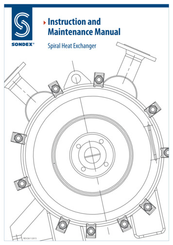
Instruction andMaintenance ManualSpiral Heat ExchangerREV26112015
1. ContentDescription . Section 2Introduction . Section 3Important safety Precautions. Section 4Generally. Section 5Correct Operation. Section 6Safety Alert Notices. Section 7Thermal Design. Section 8Installation. Section 9Maintenance. Section 102. DescriptionThis instruction book is meant as a guide in connection with installation, operation and maintenance of Sondexspiral heat exchangers. A spiral heat exchanger utilizes the spiral flow on both sides of the heat exchanger.Spiral heat exchangers are typically used for liquids-liquids ratio, gas into liquids or condensing of steam intoliquids.3. IntroductionThe instruction book can be used for all spiral heat exchangers produced and delivered by SondexSondex cannot be held responsible for damages as a result of incorrect installation; use and/or maintenanceof Sondex spiral heat exchanger, in case the instructions in this instruction book have not been observed.Please notice that our spiral heat exchangers are specially designed and built for operation conditions(pressure, temperatures, capacities and liquid types), provided by the customer. Pressure peaks overnormal working pressure or shock waves occurring by start/stop of the system may result in severedamages and must be avoided. Sondex cannot be held responsible for damages arisen as a result of anyoperation deviating from the original design conditions.4. Important safety PrecautionsFollowing points MUST be observed when working with spiral heat exchangers: Observance of local valid safety precautions. Before work is started make sure that the outlet of the spiral heat exchanger is free, emptied andcooled below 40 C. Always use gloves before handling the spiral heat exchanger in order to avoid hand injury fromsharp edges. The Law or other regulations may require acquisition of suitable protection measures in the companyYELLOW TRIANGLE: Refers to applicable SAFETY ALERT notices in this instruction book.This information is given where danger of bodily harm is present.2
5. GenerallyIdentification of the Spiral heat exchangerAll types of Sondex spiral heat exchangers are supplied with a name plate with following specifications: Type of spiral heat exchangerYear of productionManufacturing numberNominal capacity in kWEffective heating surface in m²Max. working pressure in barTest pressure in barMax. working temperature in CMax. differential pressureVolumeFlow3
6. Correct OperationThis user manual provides information and instructions for correct and safe operation of the unit. Many accidentsare caused by incorrect use! It is essential that you study the instructions carefully, and above all, ensure theavailability to those who install, maintain and operate the spiral heat exchanger on a daily basis. This manual isof no value if it is not available at the time when your staff needs it.If a problem occurs with your Sondex Spiral Heat Exchanger which is beyond the scope of this manual, do nothesitate to contact us. The installation should not be put into operation before all indistinctnesses have beensolved!To avoid injuries and damages, follow the instructions and local applicable safety regulations. Also take thenecessary protective measures, depending on the nature of your process or circumstances related to it, at yourplant.We draw your attention to the fact that our spiral heat exchangers are specially built and designed accordingto the requirements of the customers (pressure, temperature, capacity liquid types). Sudden abnormal pressureshock and pressure above working pressure at start-up/stop may result in severe damages and should beavoided. Furthermore, pressure shock from e.g. positive-pumps result in damages on the spiral heat exchanger.Sondex cannot be held responsible for damages arisen in consequence of wrong operation. In case ofamendments of the operation conditions please contact Sondex.7. Safety Alert NoticesBodily harm can be caused by: Burning as a result of touching the spiral heat exchanger or other parts of the installation: The uncontrolled release of pressurized media with which the danger of burning and other injuries is present; Contact with chemicals; Touching sharp edges of the installation.Damage to equipment can be caused by: External forces; Corrosion; Chemical action; Erosion; Material fatique; Water hammer; Thermal and/or mechanical shock Freezing; Wrong transport/lifting.Be careful by stop of the plant, as some parts may still be hot. The spiral heat exchanger is only applicable withthe media stated in the data list. For the prevention of damages the cold and hot media must run through thespiral exchanger simultaneously. In case the cold medium is not adrift simultaneously with the hot medium,the cold medium may start boiling depending on pressure and temperature/pressure and media types, andthe spiral heat exchanger may be damaged. Sudden pressure and temperature amendments should beavoided.When a spiral heat exchanger (filled with water or liquid compounds) is not in operation and is subject totemperatures below 0 C a deformaty risk is present in case of icing. In case of frost risk the spiral heat exchangermust be totally emptied.Leak risks are always available. Therefore we advise you to take this into account by installation and we4
recommend a drip tray under the spiral heat exchanger in order to avoid liquid on the floor and/or damageson associated electronic equipment (short circuit, moisture damage).If the spiral heat exchanger is used at temperatures above 60 C/or with aggressive liquids, it is recommendedto shield the spiral heat exchanger so that the risk of contact is avoided. In case of welding work near the spiralheat exchanger this must never be used as earth connection for the construction work. Voltage may resultin severe damages to the spiral heat exchanger. Therefore demount the connection flanges and thereafterisolate the spiral heat exchanger from the system.8. Thermal DesignThe construction and calculation of Sondex spiral heat exchangers are based on the newest technology. Performance tests must always take place in a totally cleaned spiral heat exchanger. The nominal performances/pressure loss are stated in the Sondex data lists.Especially with regard to the pressure loss a minor rise up to 15% must be expected on the side with the lowestworking pressure. This depends on specifications and the difference between the two working pressures.9. InstallationRequirements to the installation area:It is very important that enough space around the spiral heat exchanger is kept free for servicing of the unitInstalling the pipe connectionsThe Sondex spiral heat exchanger will be provided with flanges, connections, threaded pipes, etc.WARNINGWhen connecting the pipe system to the spiral heat exchanger make sure that no stress or strain is imposed,by the pipe system, onto the spiral heat exchanger!We advise you of the following: Heavy pipe work needs to be supported. This will prevent heavy forces on the spiral heat exchanger. Always install flexible connections on the spiral heat exchanger to prevent vibrations. These flexibleconnections also prevent expansion of the pipe work, caused by temperature influence, onto the spiralheat exchanger. The pipe work needs to be thoroughly cleaned and flushed before connecting to the spiral heat exchanger. Always install vents on both sides of the spiral heat exchanger.Valve direction and pumps:Avoid that the nominal pressure of the equipment is exceeded and take necessary precautions in order toavoid pressure chocks (water hammer). To isolate the unit it is of big importance that the connection pipesare supplied with valves.All valves must be opened slowly in order to increase the flow velocity successively at start-up. The flow velocityis reduced successively during stop. In order to secure a normal flow during maintenance bypass lines arerecommended.When using displacement pumps a decompression bypass line with a time controlled, slowly-working valveis recommended. Furthermore, take precautions by means of pressure controlled switches, pressure reliefgauges, delivery pipes when using pumps with adjustable velocities and shut-off pumps.5
Large tolerances, especially pressure drop increases beyond the nominal values stated, must be consideredwhen calculating associated products, such as pumps and spiral heat exchangers. These are results of possiblevariations of the liquid-properties, the flow velocities, boiler scale or deposits on the heat transmission surfaces.AssemblingLift the spiral heat exchanger by means of the lifting eyes only!Install any drain/pet valves.ALWAYS:Use the lifting eyes (if fitted)NEVER:Lift using the connectionsWARNINGNever lift the spiral heat exchanger by means of connections or studs.10. Maintenance10.1. PreparationRepairs must be undertaken by skilled manpower employed by Sondex and with knowledge of spiral heatexchangers. Inspection of the units must take place according to the regulations valid in the country wherethe unit is installed.10.2. Fouling and CloggingThe construction with only one single channel makes fouling velocity slow, but various kinds of deposit onthe surfaces of the walls may occur. The deposits consist of materials with a low thermal conductivity whichwill increase the total resistance of the wall. In consequence of this a layer of deposits may reduce the totalheat transfer velocity heavily and corrosion may appear in cracks below these deposits.Sondex recommend all repairs to be undertaken by skilled manpower with a thorough knowledge of spiralheat exchangers.10.3 CleaningIn order to maintain the nominal performances the heat transfer surfaces must be kept clean. Cleaning inplace (CIP) without opening the spiral heat exchanger or manual cleaning after opening the spiral heatexchanger (see below) is possible.10.4 Cleaning In Place (CIP)The most effective procedure is to rinse the spiral heat exchanger frequently without opening the doors andto use of a suitable solvent, acid or alkaline solution.The pipes must be supplied with by-pass valves enabling circulation of the detergents. In order to obtain thebest results the flow direction must be opposite the normal flow direction (Backflush). The detergents mustbe compatible with the installation and used according to instructions of Sondex. Never use solutions withchlorides. Make sure that the detergent is suitable for the gasket.The flow velocity for the detergent solution must be equal to or larger than the nominal flow velocity.However, flow velocities significantly lower than the nominal flow velocity, can have an acceptable effect,when compensating with a prolonged cleaning.After cleaning the spiral heat exchanger must be thoroughly rinsed with water in order to remove any detergentsurplus, especially when acids have been applied. Check pH and chloride content in the rinse water. The spiralheat exchanger must be totally emptied unless it is set adrift again.6
The type of solution and the cleaning frequency must be fixed in every single case. Below follows generaldirectives.Type of DepositScale Cleaning DetergentLimitationGrease, waxHot water or steam petroleumGrease, proteinsSodium hydrateMax. 15% and 60 CFouling of biological growthSodium hydrateSodium carbonateMax. 15% and 60 CMax. 15% and 60 CCalcium CarbonateCalcium SulphateSilicates, sulphideNitric acidSulphuric acidMax. 15% and 60 CMax. 3% and 20 CMetallic oxidesAlumenium oxideCorrosivesPhosphoric acidSulfamic acidCitric acidMax. 20% and 60 CMax. 5% and 50 CMax. 20% and 60 CAll acids are only intended for stainlesssteelComplex agents (EDTA)Sodium polyphosphateResidual oil, asphaltHydrocarbon depositsParaffin or naphta based solventsWARNINGOnly apply Inhibited hydrochloric acid on carbon steel. All other acids are only suitable for stainless steel.Max. 250 ppm chlorides in all acids, demineralized water and rinsing water applied for stainless steel atmax. temperatures of 60 C.Protect carbon steel parts when corroding chemicals are applied.If CIP (Cleaning In Place) is not possible, the cover is removed and the unit is cleaned mechanically or manually.Remove loose depots of fixed substances manually. A high-speed water or steam jet is recommended foreffective removal of fixed substances and deposits.7
10.5 Re-RinsingIn case of clogging because of deposits of fixed substances at the inlet or in the first part of the channel, re-rinsingmay be a good solution. Re-rinsing is turning the flow direction of the one or both liquids or rinsing with waterin the opposite direction of the normal flow direction. The flow should be bigger than the normal flow in aperiod of 15-30 minutes.Specially designed with built-in flushing connectionsLong-life gasket solutionWARNING !By inspection of a passage do not open the spiral heatexchanger before the pressure is totally shut off on bothsides of the installation!If it is the intent to inspect the one side of the spiral heat exchangerwith the other side still under pressure, the removed cover must bereplaced by a special device approved by Sondex in order to avoiddamages on the spiral body. Please contact Sondex for furtherinformation.10.6 Opening of the Unit1. Close the main valves of the in-/outlet side and let the spiral heat exchanger cool before opening.Control that: None of the sides of the spiral heat exchangers are under pressure Both sides of the spiral heat exchanger are emptied.2. Disconnect the pipes3. Most of the spiral heat exchangers are equipped with flat (or conical strengthened) coverswhich are kept down by means of suitable tools.The contact gaskets can stick to the surfaces of the covers or the surfaces of the body. When theremaining gasket material is removed, avoid damaging the surface of the covers the edges of the spiral heatexchanger body plate or the sealing ring.8
10.7 MaintenanceEach channel can be examined visually from one of the sides of the spiral heat exchanger body. If the spiralheat exchanger has a big channel width and/or a small distance it may be necessary to use an endoscope.The channels must be examined for: Corrosion - often visible at the sealed weldings near the surface of the body and thus easy to findErosion - often visible in the middle or peripheral inlet and near the distance platesFouling/clogging. In spiral heat exchangers deposits of fixed substances in the bottom part.Mechanical damage (deformation).In case of heavy corossion, erosion or a mechanical damage, contact Sondex for advice with regard to possiblerepair in place.10.8 ReassemblingDuring reassembling of the Spiral Heat Exchanger the gasket must be renewed. Even if the gasket appearsto look normal, the necessary compression properties are no longer available in the gasket due to the highcompression under service. Make sure that the contact gaskets are intact and clean before reassembling.By replacement of gaskets please contact Sondex.The gasket must be replaced after opening of the Spiral Heat Exchanger!The spiral heat exchanger is supplied with a specific number of hook bolts and the spiral heat exchanger maynot be operated with a less number or other dimensions of hook bolts. The distance between the hook boltshas to be the same distance as between the hook bolts on the cover.Tightening TorqueHead/follower and the gasket are replaced when reassembling. Gradually fasten the fang bolts diagonally to thelowest tightening torque. In order to secure that the unit is tight it is possible to increase the tightening torque,however, without exceeding the maximum value stated in below table.Hook Bolt TypeGasket TypeMin. Torque (N.M)Max. Torque (N.M)NBR/EPDM1504509
10.9 TestHydraulic testIt is possible to use normal hydraulic test procedures after total reassembling of the spiral heat exchanger.Air under water test Supply air at low pressure (0.2-0.5 bar overpressure) in the closed channel.Do not exceed 0.5 bar overpressure. Air bubbles will reveal any leaks in the channel welding. Repeat the procedure for the other channel welding, if necessary. A normal hydraulic test can be undertaken after a total reassembling of both covers. The maximumtest pressure is stated on the name plate.A hydraulic test must always be made before test by means of air or other compressed gases and may involvespecial national safety rules which must be observed. To reveal leaks by means of gas or air it is sufficient touse a very low pressure (overpressure 0.5 bar) it is also possible to use a less volatile gas (e.g. helium) insteadof putting the whole system under pressure.WARNING:It is of utmost importance to fix the side to be tested by means of cross balks. Otherwise the hydraulicpressure may deform the body and thus result in permanent or irreparable damages.Test by means of air or other compressed gases must be in accordance with any national security andregulations.Sondex Head OfficeMarsvej 5DK - 6000 KoldingDenmarkTel. 45 76 306 100Fax (1) 45 75 538 968Fax (2) 45 75 505 019info@sondex.dkwww.sondex.dkCopyright 11-2012 Sondex A/SSondex A/S can accept no responsibility for possible errors in catalogues, brochures and other printed materials.Sondex A/S reserves the right at any time to change the specifications without notice.10
The Sondex spiral heat exchanger will be provided with flanges, connections, threaded pipes, etc. WARNING When connecting the pipe system to the spiral heat exchanger make sure that no stress or strain is imposed, by the pipe system, onto the spiral heat exchanger! We advise you o