Transcription
IS42/45S81600FIS42/45S16800F16Mx8, 8Mx16JULY 2015128Mb SYNCHRONOUS DRAMFEATURES Clock frequency: 200, 166, 143 MHz Fully synchronous; all signals referenced to apositive clock edgeOVERVIEWISSI's 128Mb Synchronous DRAM achieves high-speeddata transfer using pipeline architecture. All inputs andoutputs signals refer to the rising edge of the clock input.The 128Mb SDRAM is organized as follows. Internal bank for hiding row access/precharge Power supplyIS42/45S81600FVddVddq3.3V 3.3VIS42/45S16800F3.3V 3.3V LVTTL interface Programmable burst length– (1, 2, 4, 8, full page) Programmable burst sequence:Sequential/Interleave Auto Refresh (CBR) Self Refresh 4096 refresh cycles every 16 ms (A2 grade) or64 ms (Commercial, Industrial, A1 grade) Random column address every clock cycle Programmable CAS latency (2, 3 clocks) Burst read/write and burst read/single writeoperations capability Burst termination by burst stop and prechargecommandIS42/45S81600FIS42/45S16800F4M x8 x4 Banks2M x16 x4 Banks54-pin TSOPII54-pin TSOPII54-ball BGAKEY TIMING PARAMETERSParameter-5Clk Cycle TimeCAS Latency 35CAS Latency 210Clk FrequencyCAS Latency 3200CAS Latency 2100Access Time from ClockCAS Latency 35CAS Latency 26.5-6-7 Unit61077.5nsns166100143133MhzMhz5.46.55.45.4nsns Temperature Ranges:Commercial (0oC to 70oC)Industrial (-40oC to 85oC)Automotive, A1 (-40oC to 85oC)Automotive, A2 (-40oC to 105oC)Copyright 2015 Integrated Silicon Solution, Inc. All rights reserved. ISSI reserves the right to make changes to this specification and its products at any time without notice. ISSI assumes no liability arising out of the application or use of any information, products or services described herein. Customers are advised to obtainthe latest version of this device specification before relying on any published information and before placing orders for products.Integrated Silicon Solution, Inc. does not recommend the use of any of its products in life support applications where the failure or malfunction of the product can reasonably beexpected to cause failure of the life support system or to significantly affect its safety or effectiveness. Products are not authorized for use in such applications unless IntegratedSilicon Solution, Inc. receives written assurance to its satisfaction, that:a.) the risk of injury or damage has been minimized;b.) the user assume all such risks; andc.) potential liability of Integrated Silicon Solution, Inc is adequately protected under the circumstancesIntegrated Silicon Solution, Inc. — www.issi.comRev. D07/17/20151
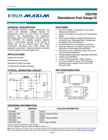
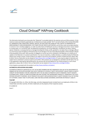
IS42/45S81600F, IS42/45S16800FDEVICE OVERVIEWThe 128Mb SDRAM is a high speed CMOS, dynamicrandom-access memory designed to operate in 3.3V Vddand 3.3V Vddq memory systems containing 134,217,728bits. Internally configured as a quad-bank DRAM with asynchronous interface. Each 33,554,432-bit bank is organized as 4,096 rows by 512 columns by 16 bits or 4,096rows by 1,024 columns by 8 bits.The 128Mb SDRAM includes an AUTO REFRESH MODE,and a power-saving, power-down mode. All signals areregistered on the positive edge of the clock signal, CLK.All inputs and outputs are LVTTL compatible.The 128Mb SDRAM has the ability to synchronously burstdata at a high data rate with automatic column-addressgeneration, the ability to interleave between internal banksto hide precharge time and the capability to randomlychange column addresses on each clock cycle duringburst access.A self-timed row precharge initiated at the end of the burstsequence is available with the AUTO PRECHARGE functionenabled. Precharge one bank while accessing one of theother three banks will hide the precharge cycles and provideseamless, high-speed, random-access operation.SDRAM read and write accesses are burst oriented startingat a selected location and continuing for a programmednumber of locations in a programmed sequence. Theregistration of an ACTIVE command begins accesses,followed by a READ or WRITE command. The ACTIVEcommand in conjunction with address bits registered areused to select the bank and row to be accessed (BA0,BA1 select the bank; A0-A11 select the row). The READor WRITE commands in conjunction with address bitsregistered are used to select the starting column locationfor the burst access.Programmable READ or WRITE burst lengths consist of1, 2, 4 and 8 locations or full page, with a burst terminateoption.FUNCTIONAL BLOCK DIAGRAM (For 2MX16X4 Banks MHDATA INBUFFERCOMMANDDECODER&CLOCKGENERATOR16DQ 0-15VDD/VDDQDATA DDRESSLATCH1212COLUMNADDRESS LATCHROWADDRESSBUFFERROW DECODERCLKCKECSRASCASWE4096409640964096MEMORY CELLARRAYBANK 0SENSE AMP I/O GATE512(x 16)BANK CONTROL LOGIC9BURST COUNTERCOLUMNADDRESS BUFFER2COLUMN DECODER9Integrated Silicon Solution, Inc. — www.issi.comRev. D07/17/2015
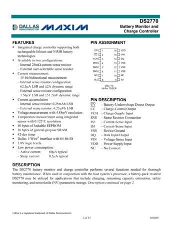
IS42/45S81600F, IS42/45S16800FPIN CONFIGURATIONS54 pin TSOP - Type II for N DESCRIPTIONSA0-A11A0-A9BA0, BA1DQ0 to DQ7CLKCKECSRASCASRow Address InputColumn Address InputBank Select AddressData I/OSystem Clock InputClock EnableChip SelectRow Address Strobe CommandColumn Address Strobe CommandIntegrated Silicon Solution, Inc. — www.issi.comRev. D07/17/2015WEDQMVddVssVddqVssqNCWrite EnableData Input/Output MaskPowerGroundPower Supply for I/O PinGround for I/O PinNo Connection3
IS42/45S81600F, IS42/45S16800FPIN CONFIGURATIONS54 pin TSOP - Type II for 2629A4VDD2728VSSPIN DESCRIPTIONSA0-A11A0-A8BA0, BA1DQ0 to DQ15CLKCKECSRASCAS4Row Address InputColumn Address InputBank Select AddressData I/OSystem Clock InputClock EnableChip SelectRow Address Strobe CommandColumn Address Strobe CommandWEDQMLDQMHVddVssVddqVssqNCWrite Enablex16 Lower Byte, Input/Output Maskx16 Upper Byte, Input/Output MaskPowerGroundPower Supply for I/O PinGround for I/O PinNo ConnectionIntegrated Silicon Solution, Inc. — www.issi.comRev. D07/17/2015
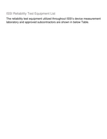
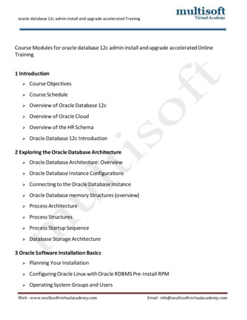
IS42/45S81600F, IS42/45S16800FPIN CONFIGURATION54-ball BGA for x16 (Top View) (8.00 mm x 8.00 mm Body, 0.8 mm Ball Pitch)package code: 54B (8x8)1 2 3 4 5 6 7 8 9ABCDEFGHJVSS DQ15 VSSQVDDQ DQ0 VDDDQ14 DQ13 VDDQVSSQ DQ2 DQ1DQ12 DQ11 VSSQVDDQ DQ4 DQ3DQ10 DQ9 VDDQVSSQ DQ6 DQ5DQ8NCVSSVDD DQML DQ7DQMH 3A2VDDPIN DESCRIPTIONSA0-A11A0-A8BA0, BA1DQ0 to DQ15CLKCKECSRASCASRow Address InputColumn Address InputBank Select AddressData I/OSystem Clock InputClock EnableChip SelectRow Address Strobe CommandColumn Address Strobe CommandIntegrated Silicon Solution, Inc. — www.issi.comRev. D07/17/2015WEDQMLDQMHVddVssVddqVssqNCWrite Enablex16 Lower Byte Input/Output Maskx16 Upper Byte Input/Output MaskPowerGroundPower Supply for I/O PinGround for I/O PinNo Connection5
IS42/45S81600F, IS42/45S16800FPIN FUNCTIONSSymbol TypeA0-A11Input PinBA0, BA1Input PinCASInput PinCKEInput PinCLKInput PinCSInput PinDQML,DQMHInput PinDQMInput PinDQ0-DQ7 orInput/OutputDQ0-DQ15RASInput PinWEVddqVddVssqVss6Input PinPower Supply PinPower Supply PinPower Supply PinPower Supply PinFunction (In Detail)Address Inputs: A0-A11 are sampled during the ACTIVEcommand (row-address A0-A11) and READ/WRITE command (column address A0A9 (x8), or A0-A8 (x16); with A10 defining auto precharge) to select one location outof the memory array in the respective bank. A10 is sampled during a PRECHARGEcommand to determine if all banks are to be precharged (A10 HIGH) or bankselected by BA0, BA1 (LOW). The address inputs also provide the op-code during aLOAD MODE REGISTER command.Bank Select Address: BA0 and BA1 defines which bank the ACTIVE, READ, WRITEor PRECHARGE command is being applied.CAS, in conjunction with the RAS and WE, forms the device command. See the"Command Truth Table" for details on device commands.The CKE input determines whether the CLK input is enabled. The next rising edgeof the CLK signal will be valid when is CKE HIGH and invalid when LOW. When CKEis LOW, the device will be in either power-down mode, clock suspend mode, or selfrefresh mode. CKE is an asynchronous input.CLK is the master clock input for this device. Except for CKE, all inputs to this deviceare acquired in synchronization with the rising edge of this pin.The CS input determines whether command input is enabled within the device.Command input is enabled when CS is LOW, and disabled with CS is HIGH. Thedevice remains in the previous state when CS is HIGH.DQML and DQMH control the lower and upper bytes of the I/O buffers. In readmode,DQML and DQMH control the output buffer. WhenDQML orDQMH is LOW, thecorresponding buffer byte is enabled, and when HIGH, disabled. The outputs go tothe HIGH impedance state whenDQML/DQMH is HIGH. This function corresponds toOE in conventional DRAMs. In write mode,DQML and DQMH control the input buffer.When DQML or DQMH is LOW, the corresponding buffer byte is enabled, and datacan be written to the device. When DQML or DQMH is HIGH, input data is maskedand cannot be written to the device. For IS42/45S16800F only.For IS42/45S81600F only.Data on the Data Bus is latched on DQ pins during Write commands, and buffered foroutput after Read commands.RAS, in conjunction with CAS and WE, forms the device command. See the "Command Truth Table" item for details on device commands.WE, in conjunction with RAS and CAS, forms the device command. See the "Command Truth Table" item for details on device commands.Vddq is the output buffer power supply.Vdd is the device internal power supply.Vssq is the output buffer ground.Vss is the device internal ground.Integrated Silicon Solution, Inc. — www.issi.comRev. D07/17/2015
IS42/45S81600F, IS42/45S16800FGENERAL DESCRIPTIONREADThe READ command selects the bank from BA0, BA1 inputsand starts a burst read access to an active row. Inputs A0A9 (x8); A0-A8 (x16) provides the starting column location.When A10 is HIGH, this command functions as an AUTOPRECHARGE command. When the auto precharge isselected, the row being accessed will be precharged atthe end of the READ burst. The row will remain open forsubsequent accesses when AUTO PRECHARGE is notselected. DQ’s read data is subject to the logic level onthe DQM inputs two clocks earlier. When a given DQMsignal was registered HIGH, the corresponding DQ’s willbe High-Z two clocks later. DQ’s will provide valid datawhen the DQM signal was registered LOW.WRITEA burst write access to an active row is initiated with theWRITE command. BA0, BA1 inputs selects the bank, andthe starting column location is provided by inputs A0-A9(x8); A0-A8 (x16). Whether or not AUTO-PRECHARGE isused is determined by A10.The row being accessed will be precharged at the end ofthe WRITE burst, if AUTO PRECHARGE is selected. IfAUTO PRECHARGE is not selected, the row will remainopen for subsequent accesses.A memory array is written with corresponding input dataon DQ’s and DQM input logic level appearing at the sametime. Data will be written to memory when DQM signal isLOW. When DQM is HIGH, the corresponding data inputswill be ignored, and a WRITE will not be executed to thatbyte/column location.PRECHARGEThe PRECHARGE command is used to deactivate theopen row in a particular bank or the open row in all banks.BA0, BA1 can be used to select which bank is prechargedor they are treated as “Don’t Care”. A10 determinedwhether one or all banks are precharged. After executing this command, the next command for the selectedbank(s) is executed after passage of the period tRP, whichis the period required for bank precharging. Once a bankhas been precharged, it is in the idle state and must beactivated prior to any READ or WRITE commands beingissued to that bank.AUTO PRECHARGEThe AUTO PRECHARGE function ensures that the precharge is initiated at the earliest valid stage within a burst.This function allows for individual-bank precharge withoutrequiring an explicit command. A10 to enable the AUTOIntegrated Silicon Solution, Inc. — www.issi.comRev. D07/17/2015PRECHARGE function in conjunction with a specific READor WRITE command. For each individual READ or WRITEcommand, auto precharge is either enabled or disabled.AUTO PRECHARGE does not apply except in full-pageburst mode. Upon completion of the READ or WRITEburst, a precharge of the bank/row that is addressed isautomatically performed.AUTO REFRESH COMMANDThis command executes the AUTO REFRESH operation.The row address and bank to be refreshed are automaticallygenerated during this operation. The stipulated period (trc) isrequired for a single refresh operation, and no other commands can be executed during this period. This commandis executed at least 4096 times for every Tref. During anAUTO REFRESH command, address bits are “Don’t Care”.This command corresponds to CBR Auto-refresh.BURST TERMINATEThe BURST TERMINATE command forcibly terminatesthe burst read and write operations by truncating eitherfixed-length or full-page bursts and the most recentlyregistered READ or WRITE command prior to the BURSTTERMINATE.COMMAND INHIBITCOMMAND INHIBIT prevents new commands from beingexecuted. Operations in progress are not affected, apartfrom whether the CLK signal is enabledNO OPERATIONWhen CS is low, the NOP command prevents unwantedcommands from being registered during idle or waitstates.LOAD MODE REGISTERDuring the LOAD MODE REGISTER command the moderegister is loaded from A0-A11. This command can onlybe issued when all banks are idle.ACTIVE COMMANDWhen the ACTIVE COMMAND is activated, BA0, BA1inputs selects a bank to be accessed, and the addressinputs on A0-A11 selects the row. Until a PRECHARGEcommand is issued to the bank, the row remains openfor accesses.7
IS42/45S81600F, IS42/45S16800FCOMMAND TRUTH TABLECKEFunctionn–1nCSRASCASWEBA1BA0A10Device deselect (DESL)H H No operation (NOP)H LHHH Burst stop (BST)H LHHL ReadH LHLHVVLRead with auto prechargeH LHLHVVHWriteH LHLLVVLWrite with auto prechargeH LHLLVVHBank activate (ACT)H LLHHVVVPrecharge select bank (PRE) H LLHLVVLPrecharge all banks (PALL) H LLHL HCBR Auto-Refresh (REF)HHLLLH Self-Refresh (SELF)HLLLLH Mode register set (MRS)H LLLLLLLA11A9 - A0 VVVVV VNote: H Vih, L Vil x Vih or Vil, V Valid Data.DQM TRUTH TABLECKEFunctionn-1nData write / output enableH Data mask / output disableH Upper byte write enable / output enableH Lower byte write enable / output enableH Upper byte write inhibit / output disableH Lower byte write inhibit / output disableH DQMULHL H LLH L HNote: H Vih, L Vil x Vih or Vil, V Valid Data.8Integrated Silicon Solution, Inc. — www.issi.comRev. D07/17/2015
IS42/45S81600F, IS42/45S16800FCKE TRUTH TABLECurrent State /FunctionActivating Clock suspend mode entryAny Clock suspend modeClock suspend mode exitAuto refresh command Idle (REF)Self refresh entry Idle (SELF)Power down entry IdleSelf refresh exitPower down exitCKEn–1HLLHHHLLLnLLHHLLHHHCS LL LH RAS LL H CAS LL H WE HH H Address Note: H Vih, L Vil x Vih or Vil, V Valid Data.Integrated Silicon Solution, Inc. — www.issi.comRev. D07/17/20159
IS42/45S81600F, IS42/45S16800FFUNCTIONAL TRUTH TABLECurrent StateCSRAS CASWEAddressCommandActionIdleHXXXXDESLNop or Power Down(2)LHHHXNOPNop or Power Down(2)LHHLXBSTNop or Power DownLHLHBA, CA, A10READ/READAILLEGAL (3)LHLLA, CA, A10WRIT/ WRITAILLEGAL(3)LLHHBA, RAACTRow activatingLLHLBA, A10PRE/PALLNopLLLHXREF/SELFAuto refresh or Self-refresh(4)LLLLOC, BA1 LMRSMode register setHXXXXDESLNopLHHHXNOPNopLHHLXBSTNopLHLHBA, CA, A10READ/READABegin read (5)LHLLBA, CA, A10WRIT/ WRITABegin write (5)LLHHBA, RAACTILLEGAL (3)LLHLBA, A10PRE/PALLPrechargePrecharge all banks(6)Row ActiveReadLLLHXREF/SELFILLEGALLLLLOC, BAMRSILLEGALHXXXXDESLContinue burst to end toRow activeLHHHXNOPContinue burst to end RowRow activeLHHLXBSTBurst stop, Row activeLHLHBA, CA, A10READ/READATerminate burst,begin new read (7)LHLLBA, CA, A10WRIT/WRITATerminate burst,begin write (7,8)LLHHBA, RAACTILLEGAL (3)LLHLBA, A10PRE/PALLTerminate burstPrechargingWriteLLLHXREF/SELFILLEGALLLLLOC, BAMRSILLEGALHXXXXDESLContinue burst to endWrite recoveringLHHHXNOPContinue burst to endWrite recoveringLHHLXBSTBurst stop, Row activeLHLHBA, CA, A10READ/READATerminate burst, start read :Determine AP (7,8)LHLLBA, CA, A10WRIT/WRITATerminate burst, new write :Determine AP (7)LLHHBA, RARA ACTILLEGAL (3)LLHLBA, A10PRE/PALLTerminate burst Precharging (9)LLLHXREF/SELFILLEGALLLLLOC, BAMRSILLEGALNote: H Vih, L Vil x Vih or Vil, V Valid Data, BA Bank Address, CA Column Address, RA Row Address, OC Op-Code10Integrated Silicon Solution, Inc. — www.issi.comRev. D07/17/2015
IS42/45S81600F, IS42/45S16800FFUNCTIONAL TRUTH TABLE Continued:Current StateCSRAS CASWEAddressCommandActionRead with autoPrechargingH DESLContinue burst to end, PrechargeLHHHxNOPContinue burst to end, PrechargeLHHL BSTILLEGALLHLHBA, CA, A10READ/READAILLEGAL (11)LHLLBA, CA, A10WRIT/ WRITAILLEGAL (11)LLHHBA, RAACTILLEGAL (3)LLHLBA, A10PRE/PALLILLEGAL (11)LLLH REF/SELFILLEGALLLLLOC, BAMRSILLEGALWrite with AutoH DESLPrechargeContinue burst to end, Writerecovering with auto prechargeLHHH NOPContinue burst to end, Writerecovering with auto prechargePrechargingRow ActivatingLHHL BSTILLEGALLHLHBA, CA, A10READ/READAILLEGAL(11)LHLLBA, CA, A10WRIT/ WRITAILLEGAL (11)LLHHBA, RAACTILLEGAL (3,11)LLHLBA, A10PRE/PALLILLEGAL (3,11)LLLH REF/SELFILLEGALLLLLOC, BAMRSILLEGALH DESLNop, Enter idle after tRPLHHH NOPNop, Enter idle after tRPLHHL BSTNop, Enter idle after tRPLHLHBA, CA, A10READ/READAILLEGAL (3)LHLLBA, CA, A10WRIT/WRITAILLEGAL (3)LLHHBA, RAACTILLEGAL(3)LLHLBA, A10PRE/PALLNop Enter idle after tRPLLLH REF/SELFILLEGALLLLLOC, BAMRSILLEGALH DESLNop, Enter bank active after tRCDLHHH NOPNop, Enter bank active after tRCDLHHL BSTNop, Enter bank active after tRCDLHLHBA, CA, A10READ/READAILLEGAL (3)LHLLBA, CA, A10WRIT/WRITAILLEGAL (3)LLHHBA, RAACTILLEGAL (3,9)LLHLBA, A10PRE/PALLILLEGAL (3)LLLH REF/SELFILLEGALLLLLOC, BAMRSILLEGALNote: H Vih, L Vil x Vih or Vil, V Valid Data, BA Bank Address, CA Column Address, RA Row Address, OC Op-CodeIntegrated Silicon Solution, Inc. — www.issi.comRev. D07/17/201511
IS42/45S81600F, IS42/45S16800FFUNCTIONAL TRUTH TABLE Continued:Current StateWrite RecoveringCSRAS CASWEAddressCommandActionH DESLNop, Enter row active after tDPLLHHH NOPNop, Enter row active after tDPLLHHL BSTNop, Enter row active after tDPLLHLHBA, CA, A10READ/READABegin read (8)LHLLBA, CA, A10WRIT/ WRITABegin new writeLLHHBA, RAACTILLEGAL (3)LLHLBA, A10PRE/PALLILLEGAL (3)LLLH REF/SELFILLEGALLLLLOC, BAMRSILLEGALWrite RecoveringH DESLNop, Enter precharge after tDPLwith AutoLHHH NOPNop, Enter precharge after tDPLPrechargeLHHL BSTNop, Enter row active after tDPLLHLHBA, CA, A10READ/READAILLEGAL(3,8,11)LHLLBA, CA, A10WRIT/WRITAILLEGAL (3,11)LLHHBA, RAACTILLEGAL (3,11)LLHLBA, A10PRE/PALLILLEGAL (3,11)LLLH REF/SELFILLEGALLLLLOC, BAMRSILLEGALH DESLNop, Enter idle after tRCLHH NOP/BSTNop, Enter idle after tRCRefreshLHLHBA, CA, A10READ/READAILLEGALLHLLBA, CA, A10WRIT/WRITAILLEGALLLHHBA, RAACTILLEGALLLHLBA, A10PRE/PALLILLEGALLLLH REF/SELFILLEGALLLLLOC, BAMRSILLEGALMode RegisterH DESLNop, Enter idle after 2 clocksAccessingLHHH NOPNop, Enter idle after 2 clocksLHHL BSTILLEGALLHL BA, CA, A10READ/WRITEILLEGALLL BA, RAACT/PRE/PALLREF/MRSILLEGALNote: H Vih, L Vil x Vih or Vil, V Valid Data, BA Bank Address, CA Column Address, RA Row Address, OC Op-CodeNotes:1. All entries assume that CKE is active (CKEn-1 CKEn H).2. If both banks are idle, and CKE is inactive (Low), the device will enter Power Down mode. All input buffers except CKE will bedisabled.3. Illegal to bank in specified states; Function may be legal in the bank indicated by Bank Address (BA), depending on the state ofthat bank.4. If both banks are idle, and CKE is inactive (Low), the device will enter Self-Refresh mode. All input buffers except CKE will bedisabled.5. Illegal if tRCD is not satisfied.6. Illegal if tRAS is not satisfied.7. Must satisfy burst interrupt condition.8. Must satisfy bus contention, bus turn around, and/or write recovery requirements.9. Must mask preceding data which don’t satisfy tDPL.10. Illegal if tRRD is not satisfied.11. Illegal for single bank, but legal for other banks.12Integrated Silicon Solution, Inc. — www.issi.comRev. D07/17/2015
IS42/45S81600F, IS42/45S16800FCKE RELATED COMMAND TRUTH TABLE(1)Current StateSelf-Refresh (S.R.)CKEOperationn-1INVALID, CLK (n - 1) would exit S.R.HSelf-Refresh Recovery(2)LSelf-Refresh Recovery(2)LIllegalLIllegalLMaintain S.R.LSelf-Refresh Recovery Idle After trcHIdle After trcHIllegalHIllegalHBegin clock suspend next cycle(5)HBegin clock suspend next cycle(5)HIllegalHIllegalH(2)Exit clock suspend next cycleLMaintain clock suspendLPower-Down (P.D.)INVALID, CLK (n - 1) would exit P.D.HEXIT P.D. -- Idle(2)LMaintain power down modeLBoth Banks IdleRefer to operations in Operative Command TableHRefer to operations in Operative Command TableHRefer to operations in Operative Command TableHAuto-RefreshHRefer to operations in Operative Command TableHRefer to operations in Operative Command TableHRefer to operations in Operative Command TableHRefer to operations in Operative Command TableHSelf-Refresh(3)HRefer to operations in Operative Command TableHPower-Down(3)LAny stateRefer to operations in Operative Command TableHother thanBegin clock suspend next cycle(4)Hlisted aboveExit clock suspend next cycleLMaintain clock XXXWE �X—X—HXL Op - CodeX—X—X—HXL Op - CodeXXXXXXXXXXNotes:1. H : High level, L : low level, X : High or low level (Don’t care).2. CKE Low to High transition will re-enable CLK and other inputs asynchronously. A minimum setuptime must be satisfiedbefore any command other than EXIT.3. Power down and Self refresh can be entered only from the both banks idle state.4. Must be legal command as defined in Operative Command Table.5. Illegal if tsrx is not satisfied.Integrated Silicon Solution, Inc. — www.issi.comRev. D07/17/201513
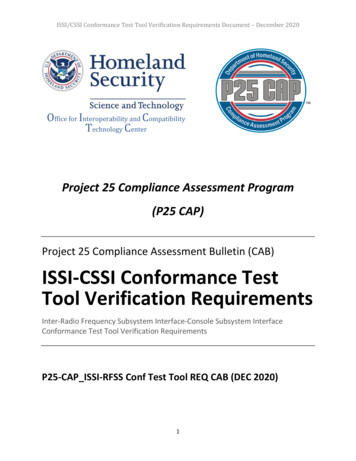
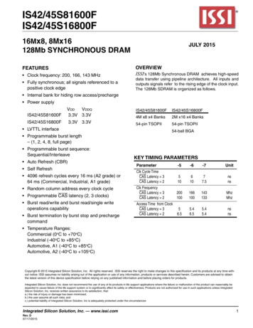
IS42/45S81600F, IS42/45S16800FSTATE DIAGRAMSelfRefreshSELFSELF exitModeRegisterSetMRSREFIDLECBR hhawiecPrriteAutoWhwitad PowerDownCKEPrechargePrechargeAutomatic sequenceManual Input14Integrated Silicon Solution, Inc. — www.issi.comRev. D07/17/2015
IS42/45S81600F, IS42/45S16800FABSOLUTE MAXIMUM RATINGS(1)SymbolParametersVdd maxMaximum Supply VoltageVddq maxMaximum Supply Voltage for Output BufferVinInput VoltageVoutOutput VoltagePd maxAllowable Power DissipationIcs Output Shorted CurrentToprOperating TemperatureCom.Ind.A1A2TstgStorage TemperatureRating–0.5 to 4.6–0.5 to 4.6–0.5 to Vdd 0.5–1.0 to Vddq 0.51500 to 70-40 to 85-40 to 85-40 to 105–55 to 150UnitVVVVWmA C CNotes:1. Stress greater than those listed under ABSOLUTE MAXIMUM RATINGS may cause permanent damage tothe device. This is a stress rating only and functional operation of the device at these or any other conditionsabove those indicated in the operational sections of this specification is not implied. Exposure to absolutemaximum rating conditions for extended periods may affect reliability.2. All voltages are referenced to Vss.DC RECOMMENDED OPERATING CONDITIONSTa 0oC to 70oC for Commercial grade. Ta -40oC to 85oC for Industrial and A1 grade. Ta -40oC to 105oC for A2 grade.SymbolParameter Min.Typ.Max.UnitVddSupply Voltage3.03.33.6VVddqI/O Supply Voltage3.03.33.6V(1)VihInput High Voltage2.0—Vddq 0.3 VVil(2)Input Low Voltage-0.3— 0.8VNote:1. Vih (max) Vddq 1.2V (pulse width 3ns).2. Vil (min) -1.2V (pulse width 3ns).3. All voltages are referenced to Vss.CAPACITANCE CHARACTERISTICS (At Ta 0 to 25 C, Vdd Vddq 3.3 0.3V)SymbolCin1Cin2Ci/oParameterInput Capacitance: CLKInput Capacitance:All other input pinsData Input/Output Capacitance:I/OsMin. Max.241.3325UnitpFpFpFTHERMAL RESISTANCEPackageSubstrateTheta-ja(Airflow 0m/s)Theta-ja(Airflow 1m/s)Theta-ja(Airflow 2m/s)Theta-jcUnitsAlloy42 TSOP2(54)4-layer89.578.573.315.4C/WCopper 2.939.136.912.5C/WIntegrated Silicon Solution, Inc. — www.issi.comRev. D07/17/201515
IS42/45S81600F, IS42/45S16800FDC ELECTRICAL CHARACTERISTICS 1 (Recommended Operation Conditions unless otherwise noted.)Symbol ParameterTest Condition-5 -6(1)Idd1Operating CurrentOne bank active, CL 3, BL 2,120100tclk tclk (min), trc trc (min)Idd2pPrecharge Standby Current CKE Vil (max), tck 15ns22(In Power-Down Mode)CS Vdd - 0.2VIdd2psPrecharge Standby Current CKE Vil (max), CLK Vil (max)2 2with clock stopCS Vdd - 0.2V(In Power-Down Mode)(2)Idd2nPrecharge Standby Current CS Vdd - 0.2V, CKE Vih (min)25 25(In Non Power-Down Mode) tck 15nsIdd2nsPrecharge Standby Current CS Vdd - 0.2V, CKE Vih (min)15 15with clock stop(In Non Power-Down Mode) All inputs stable(2)Idd3pActive Standby CurrentCKE Vil (max), CS Vdd - 0.2V66(In Power-Down Mode)tck 15nsIdd3psActive Standby CurrentCKE Vil (max), CLK Vil (max),66with clock stopCS Vdd - 0.2V(In Power-Down Mode)(2)Idd3nActive Standby CurrentCS Vdd - 0.2V, CKE Vih (min)3030(In Non Power-Down Mode) tck 15nsIdd3nsActive Standby CurrentCS Vdd - 0.2V, CKE Vih (min)20 20with clock stopAll inputs stable(In Non Power-Down Mode)Idd4Operating CurrentAll banks active, BL Full Page, CL 3, 130120tck tck (min)Idd5Auto-Refresh Currenttrc trc (min), tclk tclk (min)160140Idd6Self-Refresh CurrentCKE 0.2V2 mANotes:1. Idd (max) is specified at the output open condition.2. Input signals are changed one time during 30ns.DC ELECTRICAL CHARACTERISTICS 2 (Recommended Operation Conditions unless otherwise noted.)Symbol ParameterIilInput Leakage CurrentIolOutput Leakage CurrentVohOutput High Voltage LevelVolOutput Low Voltage Level16Test Condition0V Vin Vdd, with pins other thanthe tested pin at 0VOutput is disabled, 0V Vout Vdd,Ioh -2mAIol 2mAMin-5Max5UnitµA-52.4—5—0.4µAVVIntegrated Silicon Solution, Inc. — www.issi.comRev. D07/17/2015
IS42/45S81600F, IS42/45S16800FAC ELECTRICAL CHARACTERISTICS (1,2,3)-5 -6 -7Symbol Parameter Min. Max.Min. Max.Min. Max.Unitstck3Clock Cycle TimeCAS Latency 35—6—7—nstck2CAS Latency 210—10—7.5—nstac3Access Time From CLKCAS Latency 3—5—5.4—5.4nstac2CAS Latency 2—5.4—6.5—5.4nstchCLK HIGH Level Width2—2.5—2.5—nstclCLK LOW Level Width2—2.5—2.5—nstoh3Output Data Hold TimeCAS Latency 32.5—2.5—2.5—nstoh2CAS Latency 22.5—2.5—2.5—nstlzOutput LOW Impedance Time0—0—0—nsthz3Output HIGH Impedance Time CAS Latency 32.552.55.42.55.4nsthz2CAS Latency 22.55.42.56.52.55.4tdsInput Data Setup Time(2)1.5—1.5—1.5—nsInput Data Hold Time(2)0.8—0.8—0.8—nstdhtasAddress Setup Time(2)1.5—1.5—1.5—nstahAddress Hold Time(2)0.8—0.8—0.8—nstcksCKE Setup Time(2)1.5—1.5—1.5—ns(2)tckhCKE Hold Time0.8—0.8—0.8—nstcmsCommand Setup Time (CS, RAS, CAS, WE, DQM)(2) 1.5—1.5—1.5—nstcmhCommand Hold Time (CS, RAS, CAS, WE, DQM)(2)0.8—0.8—0.8—nstrcCommand Period (REF to REF / ACT to ACT)55—60—60—nstrasCommand Period (ACT to PRE)38100K42100K37100K nstrpCommand Period (PRE to ACT)15—18—15—nstrcdActive Command To Read / Write Command Delay Time 15—18—15—nstrrdCommand Period (ACT [0] to ACT[1])10—12—14—nstdplInput Data To Precharge10—12—14—nsCommand Delay timetdalInput Data To Active / Refresh25—30 —30 —nsCommand Delay time (During Auto-Precharge)tmrdMode Register Program Time10—12—14—nstddePower Down Exit Setup Time5.0—6.0—7.0—nstxsr Exit Self-Refresh to Active Time(4)60—67—67—nsttTransition Time0.31.20.31.20.31.2nstrefRefresh Cycle Time Ta 70oC Com, Ind, A1, A2—64—64—64ms(4096)Ta 85oC Ind, A1, A2—64—64—64msTa 85oC A2—16—16—16msNotes:1. The power-on sequence must be executed before starting memory operation.2. Measured with tt 1 ns. If clock rising time is longer than 1ns, (tt /2 - 0.5) ns should be added to the parameter.3. The reference level is 1.4V when measuring input signal timing. Rise and fall times are measured between Vih(min.) and Vil (max).4. Self-Refresh Mode is not supported for A2 grade with Ta 85oC.Integrated Silicon Solution, Inc. — www.issi.comRev. D07/17/201517
IS42/45S81600F, IS42/45S16800FOPERATING FREQUENCY / LATENCY RELATIONSHIPSSymbol Parameter-5-6-7Units—Clock Cycle TimeCAS Latency 3CAS Latency 251061077.5nsns—Operating FrequencyCAS Latency 3CAS Latency 2200100166100143133MHzMHztrcdActive Command To Read/Write Command Delay TimeCAS Latency 3CAS Latency 2323232cyclecycleRAS Latency (trcd tcac)tracCAS Latency 3CAS Latency 2646464cycletrcCommand Period (REF to REF / ACT to ACT)CAS Latency 3CAS Latency 211610698cyclecycletrasCommand Period (ACT to PRE)CAS Latency 3CAS Latency 2847565cyclecycletrpCommand Period (PRE to ACT)CAS Latency 3CAS Latency 2323232cyclecycletrrdCommand Period (ACT[0] to ACT [1])222cycletccdColumn Command Delay Time(READ, READA, WRIT, WRITA)111cycletdplInput Data To Precharge Command Delay Time222cycletdalInput Data To Active/Refresh Command Delay Time(During Auto-Precharge)CAS Latency 3CAS Latency 25454
IS42/45S81600F IS42/45S16800F Integrated Silicon Solution, Inc. — www.issi.com 1 Rev. D 07/17/2015 Copyright 2015 Integrated Silicon Solution, Inc.