Transcription
IS42S83200D, IS42S16160DIS45S83200D, IS45S16160D32Meg x 8, 16Meg x16DECEMBER 2011256-MBIT SYNCHRONOUS DRAMFEATURES Clock frequency: 166, 143 MHz Fully synchronous; all signals referenced to apositive clock edgeOVERVIEWISSI's 256Mb Synchronous DRAM achieves high-speeddata transfer using pipeline architecture. All inputs andoutputs signals refer to the rising edge of the clock input.The 256Mb SDRAM is organized as follows. Internal bank for hiding row access/precharge Single Power supply: 3.3V 0.3VIS42S83200DIS42S16160D LVTTL interface8M x 8 x 4 Banks4M x16x4 Banks Programmable burst length– (1, 2, 4, 8, full page)54-pin TSOPII54-pin TSOPII54-ball BGA54-ball BGA Programmable burst sequence:Sequential/Interleave Auto Refresh (CBR) Self Refresh 8K refresh cycles every 16 ms (A2 grade) or64 ms (commercial, industrial, A1 grade) Random column address every clock cycle Programmable CAS latency (2, 3 clocks) Burst read/write and burst read/single writeoperations capability Burst termination by burst stop and prechargecommandOPTIONS Package:54-pin TSOP-II54-ball BGA Operating Temperature Range:Commercial (0oC to 70oC)Industrial (-40oC to 85oC)Automotive Grade A1 (-40oC to 85oC)Automotive Grade A2 (-40oC to 105oC)KEY TIMING PARAMETERSParameterClk Cycle TimeCAS Latency 3CAS Latency 2Clk FrequencyCAS Latency 3CAS Latency 2Access Time from ClockCAS Latency 3CAS Latency Mhz5.46.55.46.5—5.5nsnsADDRESS TABLEParameter32M x 816M x 16Configuration8M x 8 x 4banks4M x 16 x 4banksRefresh CountCom./Ind. 8K/64msA1 8K/64msA2 8K/16ms8K/64ms8K/64ms8K/16msRow AddressesA0-A12A0-A12Column AddressesA0-A9A0-A8Bank Address PinsBA0, BA1BA0, BA1Auto Precharge PinsA10/APA10/APCopyright 2010 Integrated Silicon Solution, Inc. All rights reserved. ISSI reserves the right to make changes to this specification and its products at any time without notice. ISSI assumes no liability arising out of the application or use of any information, products or services described herein. Customers are advised to obtainthe latest version of this device specification before relying on any published information and before placing orders for products.Integrated Silicon Solution, Inc. does not recommend the use of any of its products in life support applications where the failure or malfunction of the product canreasonably be expected to cause failure of the life support system or to significantly affect its safety or effectiveness. Products are not authorized for use in such applications unless Integrated Silicon Solution, Inc. receives written assurance to its satisfaction, that:a.) the risk of injury or damage has been minimized;b.) the user assume all such risks; andc.) potential liability of Integrated Silicon Solution, Inc is adequately protected under the circumstancesIntegrated Silicon Solution, Inc. — www.issi.comRev. E12/01/20111
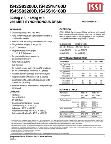
IS42S83200D, IS42S16160DIS45S83200D, IS45S16160DDEVICE OVERVIEWThe 256Mb SDRAM is a high speed CMOS, dynamicrandom-access memory designed to operate in 3.3V Vddand 3.3V Vddq memory systems containing 268,435,456bits. Internally configured as a quad-bank DRAM with asynchronous interface. Each 67,108,864-bit bank is organized as 8,192 rows by 512 columns by 16 bits or 8,192rows by 1,024 columns by 8 bits.The 256Mb SDRAM includes an AUTO REFRESH MODE,and a power-saving, power-down mode. All signals areregistered on the positive edge of the clock signal, CLK.All inputs and outputs are LVTTL compatible.The 256Mb SDRAM has the ability to synchronously burstdata at a high data rate with automatic column-addressgeneration, the ability to interleave between internal banksto hide precharge time and the capability to randomlychange column addresses on each clock cycle duringburst access.A self-timed row precharge initiated at the end of the burstsequence is available with the AUTO PRECHARGE functionenabled. Precharge one bank while accessing one of theother three banks will hide the precharge cycles and provideseamless, high-speed, random-access operation.SDRAM read and write accesses are burst oriented startingat a selected location and continuing for a programmednumber of locations in a programmed sequence. Theregistration of an ACTIVE command begins accesses,followed by a READ or WRITE command. The ACTIVEcommand in conjunction with address bits registered areused to select the bank and row to be accessed (BA0,BA1 select the bank; A0-A12 select the row). The READor WRITE commands in conjunction with address bitsregistered are used to select the starting column locationfor the burst access.Programmable READ or WRITE burst lengths consist of1, 2, 4 and 8 locations or full page, with a burst terminateoption.FUNCTIONAL BLOCK DIAGRAM (For 4Mx16x4 Banks ESHA10A12CONTROLLER16DQ 0-15VDD/VDDQDATA 9A8A7A6A5A4A3A2A1A0BA0BA1DQMLDQMHDATA CH1313COLUMNADDRESS LATCHROWADDRESSBUFFERROW DECODERCLKCKECSRASCASWE8192819281928192MEMORY CELLARRAYBANK 0SENSE AMP I/O GATE512(x 16)BANK CONTROL LOGIC9BURST COUNTERCOLUMNADDRESS BUFFER2COLUMN DECODER9Integrated Silicon Solution, Inc. — www.issi.comRev. E12/01/2011
IS42S83200D, IS42S16160DIS45S83200D, IS45S16160DPIN CONFIGURATIONS54 pin TSOP - Type II for IN DESCRIPTIONSA0-A12A0-A9BA0, BA1DQ0 to DQ7CLKCKECSRASCASRow Address InputColumn Address InputBank Select AddressData I/OSystem Clock InputClock EnableChip SelectRow Address Strobe CommandColumn Address Strobe CommandIntegrated Silicon Solution, Inc. — www.issi.comRev. E12/01/2011WEDQMVddVssVddqVssqNCWrite EnableData Input/Output MaskPowerGroundPower Supply for I/O PinGround for I/O PinNo Connection3
IS42S83200D, IS42S16160DIS45S83200D, IS45S16160DPIN CONFIGURATIONS54 pin TSOP - Type II for 32629A4VDD2728VSSPIN DESCRIPTIONSA0-A12A0-A8BA0, BA1DQ0 to DQ15CLKCKECSRASCAS4Row Address InputColumn Address InputBank Select AddressData I/OSystem Clock InputClock EnableChip SelectRow Address Strobe CommandColumn Address Strobe CommandWEDQMLDQMHVddVssVddqVssqNCWrite Enablex16 Lower Byte, Input/Output Maskx16 Upper Byte, Input/Output MaskPowerGroundPower Supply for I/O PinGround for I/O PinNo ConnectionIntegrated Silicon Solution, Inc. — www.issi.comRev. E12/01/2011
IS42S83200D, IS42S16160DIS45S83200D, IS45S16160DPIN CONFIGURATION54-ball fBGA for x16 (Top View) (8.00 mm x 13.00 mm Body, 0.8 mm Ball Pitch)package code: B1ABCDEFGHJ2 3 4 5 6 7 8 9VSS DQ15 VSSQVDDQ DQ0 VDDDQ14 DQ13 VDDQVSSQ DQ2 DQ1DQ12 DQ11 VSSQVDDQ DQ4 DQ3DQ10 DQ9 VDDQVSSQ DQ6 DQ5DQ8NCVSSVDD DQML DQ7DQMH A3A2VDDPIN DESCRIPTIONSA0-A12A0-A8BA0, BA1DQ0 to DQ15CLKCKECSRASCASRow Address InputColumn Address InputBank Select AddressData I/OSystem Clock InputClock EnableChip SelectRow Address Strobe CommandColumn Address Strobe CommandIntegrated Silicon Solution, Inc. — www.issi.comRev. E12/01/2011WEDQMLDQMHVddVssVddqVssqNCWrite Enablex16 Lower Byte Input/Output Maskx16 Upper Byte Input/Output MaskPowerGroundPower Supply for I/O PinGround for I/O PinNo Connection5
IS42S83200D, IS42S16160DIS45S83200D, IS45S16160DPIN CONFIGURATION54-ball fBGA for x8 (Top View) (8.00 mm x 13.00 mm Body, 0.8 mm Ball Pitch)package code: BABCDEFGHJ12 3 4 5 6 7 8 9VSSDQ7 VSSQVDDQ DQ0 VDDNCDQ6 VDDQVSSQ DQ1NCNCDQ5 VSSQVDDQ DQ2NCNCDQ4 VDDQVSSQ DQ3NCNCVSSVDDNCNCDQM A4A3A2VDDPIN DESCRIPTIONSA0-A12A0-A9BA0, BA1DQ0 to DQ7CLKCKECSRASCAS6Row Address InputColumn Address InputBank Select AddressData I/OSystem Clock InputClock EnableChip SelectRow Address Strobe CommandColumn Address Strobe CommandWEDQMVddVssVddqVssqNCWrite EnableByte Input/Output MaskPowerGroundPower Supply for I/O PinGround for I/O PinNo ConnectionIntegrated Silicon Solution, Inc. — www.issi.comRev. E12/01/2011
IS42S83200D, IS42S16160DIS45S83200D, IS45S16160DPIN FUNCTIONSSymbol TypeA0-A12Input PinBA0, BA1Input PinCASInput PinCKEInput PinCLKInput PinCSInput PinDQML,DQMHInput PinDQMDQ0-DQ7 orDQ0-DQ15Input PinInput/OutputFunction (In Detail)Address Inputs: A0-A12 are sampled during the ACTIVE command (row-addressA0-A12) and READ/WRITE command (column address A0-A9 (x8), or A0-A8 (x16);with A10 defining auto precharge) to select one location out of the memory array inthe respective bank. A10 is sampled during a PRECHARGE command to determineif all banks are to be precharged (A10 HIGH) or bank selected by BA0, BA1 (LOW).The address inputs also provide the op-code during a LOAD MODE REGISTERcommand.Bank Select Address: BA0 and BA1 defines which bank the ACTIVE, READ, WRITEor PRECHARGE command is being applied.CAS, in conjunction with the RAS and WE, forms the device command. See the"Command Truth Table" for details on device commands.The CKE input determines whether the CLK input is enabled. The next rising edgeof the CLK signal will be valid when is CKE HIGH and invalid when LOW. When CKEis LOW, the device will be in either power-down mode, clock suspend mode, or selfrefresh mode. CKE is an asynchronous input.CLK is the master clock input for this device. Except for CKE, all inputs to this deviceare acquired in synchronization with the rising edge of this pin.The CS input determines whether command input is enabled within the device.Command input is enabled when CS is LOW, and disabled with CS is HIGH. Thedevice remains in the previous state when CS is HIGH.DQML and DQMH control the lower and upper bytes of the I/O buffers. In readmode,DQML and DQMH control the output buffer. WhenDQML orDQMH is LOW, thecorresponding buffer byte is enabled, and when HIGH, disabled. The outputs go tothe HIGH impedance state whenDQML/DQMH is HIGH. This function corresponds toOE in conventional DRAMs. In write mode,DQML and DQMH control the input buffer.When DQML or DQMH is LOW, the corresponding buffer byte is enabled, and datacan be written to the device. WhenDQML or DQMH is HIGH, input data is maskedand cannot be written to the device. For IS42S16160D only.For IS42S83200D only.Data on the Data Bus is latched on DQ pins during Write commands, and buffered foroutput after Read commands.RASInput PinRAS, in conjunction with CAS and WE, forms the device command. See the "Command Truth Table" item for details on device commands.WEInput PinWE, in conjunction with RAS and CAS, forms the device command. See the "Command Truth Table" item for details on device commands.Vddq is the output buffer power supply.Vdd is the device internal power supply.Vssq is the output buffer ground.Vss is the device internal ground.VddqVddVssqVssPower Supply PinPower Supply PinPower Supply PinPower Supply PinIntegrated Silicon Solution, Inc. — www.issi.comRev. E12/01/20117
IS42S83200D, IS42S16160DIS45S83200D, IS45S16160DGENERAL DESCRIPTIONREADThe READ command selects the bank from BA0, BA1 inputsand starts a burst read access to an active row. Inputs A0A9 (x8); A0-A8 (x16) provides the starting column location.When A10 is HIGH, this command functions as an AUTOPRECHARGE command. When the auto precharge isselected, the row being accessed will be precharged atthe end of the READ burst. The row will remain open forsubsequent accesses when AUTO PRECHARGE is notselected. DQ’s read data is subject to the logic level onthe DQM inputs two clocks earlier. When a given DQMsignal was registered HIGH, the corresponding DQ’s willbe High-Z two clocks later. DQ’s will provide valid datawhen the DQM signal was registered LOW.WRITEA burst write access to an active row is initiated with theWRITE command. BA0, BA1 inputs selects the bank, andthe starting column location is provided by inputs A0-A9(x8); A0-A8 (x16). Whether or not AUTO-PRECHARGE isused is determined by A10.The row being accessed will be precharged at the end ofthe WRITE burst, if AUTO PRECHARGE is selected. IfAUTO PRECHARGE is not selected, the row will remainopen for subsequent accesses.A memory array is written with corresponding input dataon DQ’s and DQM input logic level appearing at the sametime. Data will be written to memory when DQM signal isLOW. When DQM is HIGH, the corresponding data inputswill be ignored, and a WRITE will not be executed to thatbyte/column location.PRECHARGEThe PRECHARGE command is used to deactivate theopen row in a particular bank or the open row in all banks.BA0, BA1 can be used to select which bank is prechargedor they are treated as “Don’t Care”. A10 determinedwhether one or all banks are precharged. After executing this command, the next command for the selectedbank(s) is executed after passage of the period tRP, whichis the period required for bank precharging. Once a bankhas been precharged, it is in the idle state and must beactivated prior to any READ or WRITE commands beingissued to that bank.AUTO PRECHARGEThe AUTO PRECHARGE function ensures that the precharge is initiated at the earliest valid stage within a burst.This function allows for individual-bank precharge withoutrequiring an explicit command. A10 to enable the AUTO8PRECHARGE function in conjunction with a specific READor WRITE command. For each individual READ or WRITEcommand, auto precharge is either enabled or disabled.AUTO PRECHARGE does not apply except in full-pageburst mode. Upon completion of the READ or WRITEburst, a precharge of the bank/row that is addressed isautomatically performed.AUTO REFRESH COMMANDThis command executes the AUTO REFRESH operation.The row address and bank to be refreshed are automaticallygenerated during this operation. The stipulated period (trc) isrequired for a single refresh operation, and no other commands can be executed during this period. This commandis executed at least 8192 times for every Tref. During anAUTO REFRESH command, address bits are “Don’t Care”.This command corresponds to CBR Auto-refresh.BURST TERMINATEThe BURST TERMINATE command forcibly terminatesthe burst read and write operations by truncating eitherfixed-length or full-page bursts and the most recentlyregistered READ or WRITE command prior to the BURSTTERMINATE.COMMAND INHIBITCOMMAND INHIBIT prevents new commands from beingexecuted. Operations in progress are not affected, apartfrom whether the CLK signal is enabledNO OPERATIONWhen CS is low, the NOP command prevents unwantedcommands from being registered during idle or waitstates.LOAD MODE REGISTERDuring the LOAD MODE REGISTER command the moderegister is loaded from A0-A12. This command can onlybe issued when all banks are idle.ACTIVE COMMANDWhen the ACTIVE COMMAND is activated, BA0, BA1inputs selects a bank to be accessed, and the addressinputs on A0-A12 selects the row. Until a PRECHARGEcommand is issued to the bank, the row remains openfor accesses.Integrated Silicon Solution, Inc. — www.issi.comRev. E12/01/2011
IS42S83200D, IS42S16160DIS45S83200D, IS45S16160DCOMMAND TRUTH TABLECKEA12, A11Functionn – 1 nCS RAS CAS WE BA1BA0A10 A9 - A0Device deselect (DESL)H H No operation (NOP)H LHHH Burst stop (BST)H LHHL ReadH LHLHVVLVRead with auto prechargeH LHLHVVHVWriteH LHLLVVLVWrite with auto prechargeH LHLLVVHVBank activate (ACT)H LLHHVVVVPrecharge select bank (PRE) H LLHLVVL Precharge all banks (PALL) H LLHL H CBR Auto-Refresh (REF)HHLLLH Self-Refresh (SELF)HLLLLH Mode register set (MRS)H LLLLLLLVNote: H Vih, L Vil x Vih or Vil, V Valid Data.DQM TRUTH TABLEFunctionData write / output enableData mask / output disableUpper byte write enable / output enableLower byte write enable / output enableUpper byte write inhibit / output disableLower byte write inhibit / output disableCKEn-1nH H H H H H DQMHLHL H DQMLLH L HNote: H Vih, L Vil x Vih or Vil, V Valid Data.Integrated Silicon Solution, Inc. — www.issi.comRev. E12/01/20119
IS42S83200D, IS42S16160DIS45S83200D, IS45S16160DCKE TRUTH TABLECurrent State /FunctionActivating Clock suspend mode entryAny Clock suspend modeClock suspend mode exitAuto refresh command Idle (REF)Self refresh entry Idle (SELF)Power down entry IdleSelf refresh exitPower down exitCKEn–1HLLHHHLLLnLLHHLLHHHCS LL LH RAS LL H CAS LL H WE HH H Address Note: H Vih, L Vil x Vih or Vil, V Valid Data.10Integrated Silicon Solution, Inc. — www.issi.comRev. E12/01/2011
IS42S83200D, IS42S16160DIS45S83200D, IS45S16160DFUNCTIONAL TRUTH TABLECurrent StateCSRAS CASWEAddressCommandActionIdleHXXXXDESLNop or Power Down(2)LHHHXNOPNop or Power Down(2)LHHLXBSTNop or Power DownLHLHBA, CA, A10READ/READAILLEGAL (3)LHLLA, CA, A10WRIT/ WRITAILLEGAL(3)LLHHBA, RAACTRow activatingLLHLBA, A10PRE/PALLNopLLLHXREF/SELFAuto refresh or Self-refresh(4)LLLLOC, BA1 LMRSMode register setHXXXXDESLNopLHHHXNOPNopLHHLXBSTNopLHLHBA, CA, A10READ/READABegin read (5)LHLLBA, CA, A10WRIT/ WRITABegin write (5)LLHHBA, RAACTILLEGAL (3)LLHLBA, A10PRE/PALLPrechargePrecharge all banks(6)LLLHXREF/SELFILLEGALLLLLOC, BAMRSILLEGALHXXXXDESLContinue burst to end toRow activeLHHHXNOPContinue burst to end RowRow activeLHHLXBSTBurst stop, Row activeLHLHBA, CA, A10READ/READATerminate burst,begin new read (7)LHLLBA, CA, A10WRIT/WRITATerminate burst,begin write (7,8)LLHHBA, RAACTILLEGAL (3)LLHLBA, A10PRE/PALLTerminate burstPrechargingLLLHXREF/SELFILLEGALLLLLOC, BAMRSILLEGALHXXXXDESLContinue burst to endWrite recoveringLHHHXNOPContinue burst to endWrite recoveringLHHLXBSTBurst stop, Row activeLHLHBA, CA, A10READ/READATerminate burst, start read :Determine AP (7,8)LHLLBA, CA, A10WRIT/WRITATerminate burst, new write :Determine AP (7)LLHHBA, RARA ACTILLEGAL (3)LLHLBA, A10PRE/PALLTerminate burst Precharging (9)LLLHXREF/SELFILLEGALLLLLOC, BAMRSILLEGALRow ActiveReadWriteNote: H Vih, L Vil x Vih or Vil, V Valid Data, BA Bank Address, CA Column Address, RA Row Address, OC Op-CodeIntegrated Silicon Solution, Inc. — www.issi.comRev. E12/01/201111
IS42S83200D, IS42S16160DIS45S83200D, IS45S16160DFUNCTIONAL TRUTH TABLE Continued:Current StateCSRAS CASWEAddressCommandActionRead with autoPrechargingH DESLContinue burst to end, PrechargeLHHHxNOPContinue burst to end, PrechargeLHHL BSTILLEGALLHLHBA, CA, A10READ/READAILLEGAL (11)LHLLBA, CA, A10WRIT/ WRITAILLEGAL (11)LLHHBA, RAACTILLEGAL (3)LLHLBA, A10PRE/PALLILLEGAL (11)LLLH REF/SELFILLEGALLLLLOC, BAMRSILLEGALH DESLContinue burst to end, Writerecovering with auto prechargeLHHH NOPContinue burst to end, Writerecovering with auto prechargeLHHL BSTILLEGALLHLHBA, CA, A10READ/READAILLEGAL(11)LHLLBA, CA, A10WRIT/ WRITAILLEGAL (11)LLHHBA, RAACTILLEGAL (3,11)LLHLBA, A10PRE/PALLILLEGAL (3,11)LLLH REF/SELFILLEGALLLLLOC, BAMRSILLEGALH DESLNop, Enter idle after tRPLHHH NOPNop, Enter idle after tRPLHHL BSTNop, Enter idle after tRPLHLHBA, CA, A10READ/READAILLEGAL (3)LHLLBA, CA, A10WRIT/WRITAILLEGAL (3)LLHHBA, RAACTILLEGAL(3)LLHLBA, A10PRE/PALLNop Enter idle after tRPLLLH REF/SELFILLEGALLLLLOC, BAMRSILLEGALH DESLNop, Enter bank active after tRCDLHHH NOPNop, Enter bank active after tRCDLHHL BSTNop, Enter bank active after tRCDLHLHBA, CA, A10READ/READAILLEGAL (3)LHLLBA, CA, A10WRIT/WRITAILLEGAL (3)LLHHBA, RAACTILLEGAL (3,9)LLHLBA, A10PRE/PALLILLEGAL (3)LLLH REF/SELFILLEGALLLLLOC, BAMRSILLEGALWrite with AutoPrechargePrechargingRow ActivatingNote: H Vih, L Vil x Vih or Vil, V Valid Data, BA Bank Address, CA Column Address, RA Row Address, OC Op-Code12Integrated Silicon Solution, Inc. — www.issi.comRev. E12/01/2011
IS42S83200D, IS42S16160DIS45S83200D, IS45S16160DFUNCTIONAL TRUTH TABLE Continued:Current StateWrite RecoveringCSRAS CASWEAddressCommandActionH DESLNop, Enter row active after tDPLLHHH NOPNop, Enter row active after tDPLLHHL BSTNop, Enter row active after tDPLLHLHBA, CA, A10READ/READABegin read (8)LHLLBA, CA, A10WRIT/ WRITABegin new writeLLHHBA, RAACTILLEGAL (3)LLHLBA, A10PRE/PALLILLEGAL (3)LLLH REF/SELFILLEGALLLLLOC, BAMRSILLEGALWrite RecoveringH DESLNop, Enter precharge after tDPLwith AutoLHHH NOPNop, Enter precharge after tDPLPrechargeLHHL BSTNop, Enter row active after tDPLLHLHBA, CA, A10READ/READAILLEGAL(3,8,11)LHLLBA, CA, A10WRIT/WRITAILLEGAL (3,11)LLHHBA, RAACTILLEGAL (3,11)LLHLBA, A10PRE/PALLILLEGAL (3,11)LLLH REF/SELFILLEGALLLLLOC, BAMRSILLEGALH DESLNop, Enter idle after tRCLHH NOP/BSTNop, Enter idle after tRCRefreshLHLHBA, CA, A10READ/READAILLEGALLHLLBA, CA, A10WRIT/WRITAILLEGALLLHHBA, RAACTILLEGALLLHLBA, A10PRE/PALLILLEGALLLLH REF/SELFILLEGALLLLLOC, BAMRSILLEGALMode RegisterH DESLNop, Enter idle after 2 clocksAccessingLHHH NOPNop, Enter idle after 2 clocksLHHL BSTILLEGALLHL BA, CA, A10READ/WRITEILLEGALLL BA, RAACT/PRE/PALLREF/MRSILLEGALNote: H Vih, L Vil x Vih or Vil, V Valid Data, BA Bank Address, CA Column Address, RA Row Address, OC Op-CodeNotes:1. All entries assume that CKE is active (CKEn-1 CKEn H).2. If both banks are idle, and CKE is inactive (Low), the device will enter Power Down mode. All input buffers except CKE will bedisabled.3. Illegal to bank in specified states; Function may be legal in the bank indicated by Bank Address (BA), depending on the state ofthat bank.4. If both banks are idle, and CKE is inactive (Low), the device will enter Self-Refresh mode. All input buffers except CKE will bedisabled.5. Illegal if tRCD is not satisfied.6. Illegal if tRAS is not satisfied.7. Must satisfy burst interrupt condition.8. Must satisfy bus contention, bus turn around, and/or write recovery requirements.9. Must mask preceding data which don’t satisfy tDPL.10. Illegal if tRRD is not satisfied.11. Illegal for single bank, but legal for other banks.Integrated Silicon Solution, Inc. — www.issi.comRev. E12/01/201113
IS42S83200D, IS42S16160DIS45S83200D, IS45S16160DCKE RELATED COMMAND TRUTH TABLE(1)Current StateSelf-Refresh (S.R.)CKEOperationINVALID, CLK (n - 1) would exit S.R.Self-Refresh Recovery(2)Self-Refresh Recovery(2)IllegalIllegalMaintain S.R.Self-Refresh Recovery Idle After trcIdle After trcIllegalIllegalBegin clock suspend next cycle(5)Begin clock suspend next cycle(5)IllegalIllegalExit clock suspend next cycle(2)Maintain clock suspendPower-Down (P.D.)INVALID, CLK (n - 1) would exit P.D.EXIT P.D. -- Idle(2)Maintain power down modeAll Banks IdleRefer to operations in Operative Command TableRefer to operations in Operative Command TableRefer to operations in Operative Command TableAuto-RefreshRefer to operations in Operative Command TableRefer to operations in Operative Command TableRefer to operations in Operative Command TableRefer to operations in Operative Command TableSelf-Refresh(3)Refer to operations in Operative Command TablePower-Down(3)Any stateRefer to operations in Operative Command Tableother thanBegin clock suspend next cycle(4)listed aboveExit clock suspend next cycleMaintain clock XXCASXXHLXXXHLXXHLXXXXXXXXHLLXXHLLXXXXXWE �X—X—HXL Op - CodeX—X—X—HXL Op - CodeXXXXXXXXXXNotes:1. H : High level, L : low level, X : High or low level (Don’t care).2. CKE Low to High transition will re-enable CLK and other inputs asynchronously. A minimum setuptime must be satisfied before any command other than EXIT.3. Power down and Self refresh can be entered only from the both banks idle state.4. Must be legal command as defined in Operative Command Table.5. Illegal if txsr is not satisfied.14Integrated Silicon Solution, Inc. — www.issi.comRev. E12/01/2011
IS42S83200D, IS42S16160DIS45S83200D, IS45S16160DSTATE DIAGRAMSelfRefreshSELFSELF exitModeRegisterSetMRSREFIDLECBR TEWRITEASUSPENDBSThwitad PowerDownCKEPrechargePrechargeAutomatic sequenceManual InputIntegrated Silicon Solution, Inc. — www.issi.comRev. E12/01/201115
IS42S83200D, IS42S16160DIS45S83200D, IS45S16160DABSOLUTE MAXIMUM RATINGS(1)SymbolParametersVdd maxMaximum Supply VoltageVddq maxMaximum Supply Voltage for Output BufferVinInput VoltageVoutOutput VoltagePd maxAllowable Power DissipationIcs Output Shorted CurrentToprOperating TemperatureCom.Ind.A1A2TstgStorage TemperatureRating–0.5 to 4.6–0.5 to 4.6–0.5 to Vdd 0.5–1.0 to Vddq 0.51500 to 70–40 to 85–40 to 85–40 to 105–65 to 150UnitVVVVWmA C CNotes:1. Stress greater than those listed under ABSOLUTE MAXIMUM RATINGS may cause permanent damage tothe device. This is a stress rating only and functional operation of the device at these or any other conditionsabove those indicated in the operational sections of this specification is not implied. Exposure to absolutemaximum rating conditions for extended periods may affect reliability.2. All voltages are referenced to Vss.DC RECOMMENDED OPERATING CONDITIONS(Ta 0oC to 70oC for Commercial grade. Ta -40oC to 85oC for Industrial and A1 grade. Ta -40oC to 105oC for A2 grade.)SymbolParameterMin.Typ.Max.UnitVddSupply Voltage3.03.33.6VVddqI/O Supply Voltage3.03.33.6VVih(1)Input High Voltage2.0—Vddq 0.3V(2)VilInput Low Voltage-0.3— 0.8VNote:1. Vih (overshoot): Vih (max) Vddq 1.2V (pulse width 3ns).2. Vil (undershoot): Vih (min) -1.2V (pulse width 3ns).3. All voltages are referenced to Vss.CAPACITANCE CHARACTERISTICS (At Ta 0 to 25 C, Vdd Vddq 3.3 0.3V)SymbolCin1Cin2CI/O16ParameterInput Capacitance: CLKInput Capacitance:All other input pinsData Input/Output Capacitance: DQSMin.2.52.54.0Max.3.53.86.0UnitpFpFpFIntegrated Silicon Solution, Inc. — www.issi.comRev. E12/01/2011
IS42S83200D, IS42S16160DIS45S83200D, IS45S16160DDC ELECTRICAL CHARACTERISTICS 1 (Recommended Operation Conditions unless otherwise noted.)SymbolIdd1 (1)ParameterOperating CurrentIdd2pPrecharge Standby Current(In Power-Down Mode)Precharge Standby Current CKE Vil (max), CLK Vil (max)(In Power-Down Mode)Precharge Standby Current CS Vcc - 0.2V, CKE Vih (min)(In Non Power-Down Mode) tck 15nsPrecharge Standby Current CS Vcc - 0.2V, CKE Vih (min)(In Non Power-Down Mode) or CKE Vil (max), All inputs stableActive Standby CurrentCKE Vil (max), tck 15ns(Power-Down Mode)Active Standby CurrentCKE Vil (max), CLK Vil (max)(Power-Down Mode)Active Standby CurrentCS Vcc - 0.2V, CKE Vih (min)(In Non Power-Down Mode) tck 15nsActive Standby CurrentCS Vcc - 0.2V, CKE Vih (min)(In Non Power-Down Mode) or CKE Vil (max), All inputs stableOperating CurrentAll banks active, BL 4, CL 3,tck tck (min)Auto-Refresh Currenttrc trc (min), tclk tclk (min)Self-Refresh CurrentCKE 0.2VIdd2psIdd2n (2)Idd2nsIdd3pIdd3psIdd3n (2)Idd3nsIdd4Idd5Idd6Test ConditionOne bank active, CL 3, BL 1,tclk tclk (min), trc trc (min)CKE Vil (max), tck 03mAmANotes:1. Idd (max) is specified at the output open condition.2. Input signals are changed one time during 30ns.DC ELECTRICAL CHARACTERISTICS 2 (Recommended Operation Conditions unless otherwise noted.)SymbolIilParameterInput Leakage CurrentIolVohVolOutput Leakage CurrentOutput High Voltage LevelOutput Low Voltage LevelTest Condition0V Vin Vcc, with pins other thanthe tested pin at 0VOutput is disabled, 0V Vout Vcc,Ioh -2mAIol 2mAIntegrated Silicon Solution, Inc. — www.issi.comRev. E12/01/2011Min-5Max5UnitµA-52.4—5—0.4µAVV17
IS42S83200D, IS42S16160DIS45S83200D, IS45S16160DAC ELECTRICAL CHARACTERISTICS lParameterClock Cycle TimeCAS Latency 3CAS Latency 2Access Time From CLKCAS Latency 3CAS Latency 2CLK HIGH Level WidthCLK LOW Level WidthOutput Data Hold TimeCAS Latency 3CAS Latency 2Output LOW Impedance TimeOutput HIGH Impedance TimeInput Data Setup Time(2)Input Data Hold Time(2)Address Setup Time(2)Address Hold Time(2)CKE Setup Time(2)CKE Hold Time(2)Command Setup Time (CS, RAS, CAS, WE, DQM)(2)Command Hold Time (CS, RAS, CAS, WE, DQM)(2)Command Period (REF to REF / ACT to ACT)Command Period (ACT to PRE)Command Period (PRE to ACT)Active Command To Read / Write Command Delay TimeCommand Period (ACT [0] to ACT[1])Input Data To PrechargeCommand Delay timetdalInput Data To Active / RefreshCommand Delay time (During Auto-Precharge)tmrdMode Register Program TimetddePower Down Exit Setup Timetxsr Exit Self-Refresh to Active Time(4)ttTransition TimetrefRefresh Cycle Time (8192)Ta 70oC Com., Ind., A1, A2Ta 85oC Ind., A1, A2Ta 85oC nsnsns646416———646416msmsmsNotes:1. The power-on sequence must be executed before starting memory operation.2. Measured with tt 1 ns. If clock rising time is longer than 1ns, (tr /2 - 0.5) ns should be added to the parameter.3. The reference level is 1.4V when measuring input signal timing. Rise and fall times are measured between Vih(min.) and Vil(max).4. Self-Refresh Mode is not supported for A2 grad
IS42S83200D, IS42S16160D IS45S83200D, IS45S16160D Integrated Silicon Solution, Inc. — www.issi.com 1 Rev. E 12/01/2011 Copyright 2010 Integrated Silicon Solution .
