Transcription
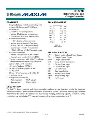
19-4634; 5/09DS2780Standalone Fuel Gauge ICwww.maxim-ic.comGENERAL DESCRIPTIONFEATURESThe DS2780 measures voltage, temperature andcurrent, and estimates available capacity forrechargeable Lithium Ion and Lithium Ion Polymerbatteries. Cell characteristics and applicationparameters used in the calculations are stored in onchip EEPROM. The available capacity registersreport a conservative estimate of the amount ofcharge that can be removed given the currenttemperature, discharge rate, stored charge andapplication parameters. Capacity estimation reportedin mAh remaining and percentage of full. APPLICATIONS Digital Still CamerasSub-Notebook ComputersPrecision Voltage, Temperature, and CurrentMeasurement SystemInternal Time Base is Accurate and TemperatureStableAbsolute and Relative Capacity Estimated fromCoulomb Count, Discharge Rate, Temperatureand Battery Cell CharacteristicsAccurate Warning of Low Battery ConditionsAutomatic Backup of Coulomb Count and AgeEstimation to Nonvolatile (NV) EEPROMGain and Tempco Calibration Allows the Use ofLow-Cost Sense Resistors24-Byte Battery/Application Parameter EEPROM16-Byte User EEPROMUnique ID and Multidrop 1-Wire InterfaceTiny 8-pin TSSOP & 10-pin TDFN PackageEmbeds Easily in Battery Packs Using ThinPrismatic Cells Handheld PC Data Terminals3G Multimedia Wireless HandsetsPIN CONFIGURATIONTYPICAL OPERATING CIRCUITPK DATA1K500DS27801505.6VDQ54 VDDPIO83 VINNC16 OVDSNS72 VSSTSSOP-81 RING INFORMATIONPARTDS2780EDS2780E/T&RDS2780E DS2780E T&RDS2780G DS2780G T&RMARKING278027802780278027802780PACKAGE INFORMATIONTSSOPTSSOP Tape-and-ReelTSSOPTSSOP Tape-and-ReelTDFNTDFN Tape-and-Reel Denotes lead(Pb)-free/RoHS-compliant package.1-Wire is a registered trademark of Maxim Integrated Products, Inc.Note: Some revisions of this device may incorporate deviations from published specifications known as errata. Multiple revisions of any devicemay be simultaneously available through various sales channels. For information about device errata, click here: www.maxim-ic.com/errata.1 of 31
DS2780 Standalone Fuel Gauge ICABSOLUTE MAXIMUM RATINGSVoltage Range on Any Pin Relative to VSSVoltage on VIN Relative to VSSOperating Temperature RangeStorage Temperature RangeSoldering Temperature (10s)-0.3V to 6.0V-0.3V to (VDD 0.3V)-40 C to 85 C-55 C to 125 CSee JEDEC J-STD-020Stresses beyond those listed under “Absolute Maximum Ratings” may cause permanent damage to the device. These are stress ratings only,and functional operation of the device at these or any other conditions beyond those indicated in the operational sections of the specifications isnot implied. Exposure to the absolute maximum rating conditions for extended periods may affect device reliability.RECOMMENDED DC OPERATING CHARACTERISTICS(VDD 2.5V to 4.5V, TA -20 C to 70 C, unless otherwise noted. Typical values are at TA 25 C.)PARAMETERSupply VoltageOVD VoltageSYMBOLVDDDQ, PIO Voltage RangeCONDITIONSMINTYPMAXUNITS(Note 1)(Note 1) 2.5-0.3 4.5 4.5VV(Note 1)-0.3 5.5VDC ELECTRICAL CHARACTERISTICS(VDD 2.5V to 4.5V, TA -20 C to 70 C, unless otherwise noted. Typical values are at TA 25 C.)PARAMETERSYMBOLCONDITIONS2.5V VDD 4.2VACTIVE CurrentIACTIVESLEEP Mode CurrentISLEEP2.5V VDD 4.2VVIHVILVOLIPD(Note 1)(Note 1)IOL 4mA (Note 1)VDQ, VPIO 0.4VInput Logic High: DQ, PIOInput Logic Low: DQ, PIOOutput Logic Low: DQ, PIOPulldown Current: DQ, PIOMINTYPMAX6595105Input Logic High: OVDVIH(Note 1)Input Logic Low: OVDVIN Input ResistanceDQ CapacitanceDQ SLEEP TimeoutUndervoltage SLEEPThresholdVILRINCDQ(Note 1)1UNITSµA3µA0.60.4VVVµA1.50.2VDD –0.2VVSS 0.2tSLEEPDQ VIL (Note 5)1.5502.02.5VM pFsVSLEEP(Note 1)2.402.452.50V15ELECTRICAL CHARACTERISTICS: TEMPERATURE, VOLTAGE, CURRENT(VCC 2.5V to 4.5V, TA -20 C to 70 C, unless otherwise noted. Typical values are at TA 25 C.)PARAMETERSYMBOLTemperature ResolutionTLSBTemperature ErrorTERRVoltage ResolutionVLSBVoltage Full-ScaleVFSVoltage ErrorVERRCurrent ResolutionILSBCONDITIONSMINTYPMAX0.125 C 34.8801.562 of 31UNITS CmV4.992V 50mVµV
DS2780 Standalone Fuel Gauge ICPARAMETERSYMBOLCurrent Full-ScaleIFSCurrent Gain ErrorIGERRCurrent Offset ErrorIOERRAccumulated Current OffsetqOERRTimebase ErrortERRCONDITIONSMINTYP(Note 2)0 C TA 70 C,2.5V VDD 4.2V(Note 4)0 C TA 70 C,2.5V VDD 4.2VVSNS VSS, (Notes 3,4)VDD 3.8V, TA 25 CMAXUNITS 51.2mV% FullScale 1-7.82 12.5µV-188 0µVhr/day 10 C TA 70 C,2.5V VDD 4.2V 2% 3ELECTRICAL CHARACTERISTICS: 1-WIRE INTERFACE, STANDARD(VCC 2.5V to 4.5V, TA -20 C to 70 C.)PARAMETERSYMBOLCONDITIONSMINTYPMAXUNITS120 sTime SlottSLOT60Recovery TimetREC1Write-0 Low TimetLOW060120 sWrite-1 Low TimetLOW1115 sRead Data ValidtRDV15 sReset Time HightRSTH480Reset Time LowtRSTL480960 sPresence Detect HightPDH1560 sPresence Detect LowtPDL60240 sMAXUNITS16 s s sELECTRICAL CHARACTERISTICS: 1-WIRE INTERFACE, OVERDRIVE(VCC 2.5V to 4.5V, TA -20 C to 70 C.)PARAMETERSYMBOLCONDITIONSMINTYPTime SlottSLOT6Recovery TimetREC1Write-0 Low TimetLOW0616 sWrite-1 Low TimetLOW112 sRead Data ValidtRDV2 sReset-Time HightRSTH48Reset-Time LowtRSTL4880 sPresence-Detect HightPDH26 sPresence-Detect LowtPDL824 s3 of 31 s s
DS2780 Standalone Fuel Gauge ICEEPROM RELIABILITY SPECIFICATION(VCC 2.5V to 4.5V, TA -20 C to 70 C, unless otherwise noted. Typical values are at TA 25 C.)PARAMETERSYMBOLEEPROM Copy TimetEECEEPROM Copy EnduranceNEECCONDITIONSTA 50 CMINTYPMAXUNITS10ms50,000cyclesNote 1: All voltages are referenced to VSS.Note 2: Factory calibrated accuracy. Higher accuracy can be achieved by in-system calibration by the user.Note 3: Accumulation bias register set to 00h.Note 4: Parameters guaranteed by design.Note 5: The application must wait for the maximum DQ SLEEP Timeout to confirm that the IC has entered sleepmode.PIN DESCRIPTIONNAMETSSOPPINTDFNPINNC11VSS22, 3VIN34VDD45DQ56OVD67NC—8Not Connected. Pin not connected internally, float or connect to VSS.SNS79Sense Resistor Connection. Connect to the negative terminal of the battery pack.Connect the sense resistor between VSS and SNS.PIO810Programmable I/O Pin. Can be configured as input or output to monitor or controluser-defined external circuitry. Output driver is open drain. This pin has an weakinternal pulldown (IPD).PAD—PADFUNCTIONNot Connected. Pin not connected internally, float or connect to VSS.Device Ground. Connect directly to the negative terminal of the battery cell. Connectthe sense resistor between VSS and SNS.Voltage Sense Input. The voltage of the battery cell is monitored through this inputpin.Power-Supply Input. Connect to the positive terminal of the battery cell through adecoupling network.Data Input/Output. 1-Wire data line. Open-drain output driver. Connect this pin to theDATA terminal of the battery pack. This pin has a weak internal pulldown (IPD) forsensing pack disconnection from host or charger.1-Wire Bus Speed Control. Input logic level selects the speed of the 1-Wire bus.Logic 1 selects overdrive (OVD) and Logic 0 selects standard timing (STD). On amultidrop bus, all devices must operate at the same speed.Exposed Pad. Connect to VSS or leave floating. (Only present on TDFN package)4 of 31
DS2780 Standalone Fuel Gauge ICFigure 1. Block DiagramDETAILED DESCRIPTIONThe DS2780 operates directly from 2.5V to 4.5V and supports single cell Lithium-ion battery packs. As shown inFigure 2, the DS2780 accommodates multicell applications by adding a voltage regulator for VDD and voltagedivider for VIN. Nonvolatile storage is provided for cell compensation and application parameters. Host sidedevelopment of fuel-gauging algorithms is eliminated. On-chip algorithms and convenient status reporting ofoperating conditions reduce the serial polling required of the host processor. For 2-cell applications, the DS2781 isrecommended, since it includes a voltage regulator and accepts VIN up to 10V.Additionally, 16 bytes of EEPROM memory are made available for the exclusive use of the host system and/orpack manufacturer. The additional EEPROM memory can be used to facilitate battery lot and date tracking andnon-volatile storage of system or battery usage statistics.A Dallas 1-Wire interface provides serial communication at the standard 16kbps or overdrive 140kbps speeds. Itallows access to data registers, control registers and user memory. A unique, factory programmed 64-bitregistration number (8-bit family code 48-bit serial number 8-bit CRC) assures that no two parts are alike andenables absolute traceability. The Dallas 1-Wire interface on the DS2780 supports multidrop capability so thatmultiple slave devices may be addressed with a single pin.5 of 31
DS2780 Standalone Fuel Gauge ICFigure 2. Multicell Application ExamplePK 0.1uF4.7uF500DATAPIO150DQVDD(n * ProtectionCircuit0.1uFRSNSPK-(1) Components improve IEC1004 Air/Contact ESD complianceFigure 3. Inside Protector ExamplePK KLi-IonBatteryVINOVDSNSVSS0.1uFRSNSCircuit(1) Precaution must be taken to ensure that a charge path is not created fromPK to Data or PIO.PROTECTOR CIRCUIT LOCATIONThe battery protection circuitry can be located inside or outside the DS2780. Either location is acceptable but thereare some advantages and disadvantages to both. With the protection circuit located inside, see Figure 2 andTypical Operating Circuit on page 1, the DS2780 will loose power in a circuit protection event. The DS2780 stores6 of 31
DS2780 Standalone Fuel Gauge ICfuel gauge data to EEPROM, but some data loss can occur depending on the timing of the protection event and thebackup. When the protection circuit is connected directly to the battery the protection is absolute, no charging willoccur during a protection event. With the protection circuit located outside, see Figure 3, the DS2780 will remainpowered up during a protection event. The disadvantage to this configuration is that you run the risk ofovercharging the battery by creating an unintentional charge path from PK to DATA or PIO (VPK VCELL VDIODE).Communication to the DS2780 is broken during a protection event regardless of protector location.POWER MODESThe DS2780 has two power modes: ACTIVE and SLEEP. On initial power up, the DS2780 defaults to ACTIVEmode. While in ACTIVE mode, the DS2780 is fully functional with measurements and capacity estimationcontinuously updated. In SLEEP mode, the DS2780 conserves power by disabling measurement and capacityestimation functions, but preserves register contents. SLEEP mode is entered under two different conditions andan enable bit for each condition makes entry into SLEEP optional. SLEEP mode can be enabled using the PowerMode (PMOD) bit or the Under Voltage Enable (UVEN) bit.The PMOD type SLEEP is entered if the PMOD bit is set AND DQ is low for tSLEEP (2s nominal). The condition ofDQ low for tSLEEP can be used to detect a pack disconnection or system shutdown, in which no charge or dischargecurrent will flow. A PMOD SLEEP condition transitions back to ACTIVE mode when DQ is pulled high.The second option for entering SLEEP is an under voltage condition. When the UVEN bit is set, the DS2780transitions to SLEEP if the voltage on VIN is less than VSLEEP (2.45V nominal) AND DQ is stable at a low or highlogic level for tSLEEP. An under-voltage condition occurs when a pack is fully discharged, where loading on thebattery should be minimized. UVEN type SLEEP relieves the battery of the IACTIVE load until communication on DQresumes.NOTE: PMOD and UVEN SLEEP features must be disabled when a battery is charged on an external charger thatdoes not connect to the DQ pin. PMOD SLEEP can be used if the charger pulls DQ high. UVEN SLEEP can beused if the charger toggles DQ. The DS2780 remains in SLEEP on a charger that fails to properly drive DQ andtherefore does not measure or accumulate current when a battery is charged.INITIATING COMMUNICATION IN SLEEPWhen beginning communication with a DS2780 in PMOD SLEEP, DQ must be pulled up first and then a 1-WireReset pulse must be issued by the master. In UVEN SLEEP, the procedure depends on the state of DQ whenUVEN SLEEP was entered. If DQ was low, DQ must be pulled up and then a 1-Wire Reset pulse must be issuedby the master as with PMOD SLEEP. If DQ was high when UVEN SLEEP was entered, then the DS2780 isprepared to receive a 1-Wire reset from the master. In the first two cases with DQ low during SLEEP, the DS2780does not respond to the first rising edge of DQ with a presence pulse.VOLTAGE MEASUREMENTBattery voltage is measured at the VIN input with respect to VSS. It has a range of 0V to 4.992V (pin voltagelimited to 4.5V) and a resolution of 4.88mV. The measurement is stored in the VOLTAGE register in two’scompliment form and is updated every 440ms. Voltages above the maximum register value are reported at themaximum value; voltages below the minimum register value are reported at the minimum value. The format of thevoltage register is shown in Figure 4.Figure 4. Voltage Register FormatRead OnlyVOLTMSB—Address 0ChS292827MSb2625LSB—Address 0Dh2423LSb22MSb2120XXXXXLSbUnits: 4.88mV“S”: sign bit(s), “X”: reserved7 of 31
DS2780 Standalone Fuel Gauge ICVIN is usually connected to the positive terminal of a single cell Lithium-Ion battery via a 1k resistor. The inputimpedance is large enough (15M ) to be connected to a high impedance voltage divider in order to supportmultiple cell applications. The pack voltage should be divided by the number of series cells to present a single cellaverage voltage to the VIN input. In Figure 2, the value of R can be up to 1M without incurring significant errordue to input loading.TEMPERATURE MEASUREMENTThe DS2780 uses an integrated temperature sensor to measure battery temperature with a resolution of 0.125 C.Temperature measurements are updated every 440ms and placed in the temperature register in two’s complementform. The format of the temperature register is shown in Figure 5.Figure 5. Temperature Register FormatRead OnlyTEMPMSB—Address 0AhS2928272625LSB—Address 0Bh24MSb2322LSb2120XXXXMSbXLSbUnits: 0.125 C“S”: sign bit(s), “X”: reservedCURRENT MEASUREMENTIn the ACTIVE mode of operation, the DS2780 continually measures the current flow into and out of the battery bymeasuring the voltage drop across a low-value current-sense resistor, RSNS. The voltage-sense range betweenSNS and VSS is 51.2mV. The input linearly converts peak signal amplitudes up to 102.4mV as long as thecontinuous signal level (average over the conversion cycle period) does not exceed 51.2mV. The ADC samplesthe input differentially at 18.6kHz and updates the Current register at the completion of each conversion cycle.The Current register is updated every 3.515s with the current conversion result in two’s complement form. Chargecurrents above the maximum register value are reported at the maximum value (7FFFh 51.2mV). Dischargecurrents below the minimum register value are reported at the minimum value (8000h -51.2mV).Figure 6. Current Register FormatRead OnlyCURRENTMSB—Address 0EhS214213212211210LSB—Address 0Fh29MSb2827LSb2625242322MSbUnits:CURRENT RESOLUTION (1 LSB)1.5625 VRSNS20m 78.13 A15m 104.2 A8 of 3120LSb“S”: sign bit(s)VSS VSNS2110m 156.3 A5m 312.5 A1.5625 V/Rsns
DS2780 Standalone Fuel Gauge ICAVERAGE CURRENT MEASUREMENTThe Average Current register reports an average current level over the preceding 28 seconds. The register value isupdated every 28s in two’s complement form, and is the average of the 8 preceding Current register updates. Theformat of the Average Current register is shown in Figure 7. Charge currents above the maximum register valueare reported at the maximum value (7FFFh 51.2mV). Discharge currents below the minimum register value arereported at the minimum value (8000h -51.2mV).Figure 7. Average Current Register FormatRead OnlyIAVGMSB—Address 08hS214213212211210MSbLSB—Address 09h292827LSb26252423MSb“S”: sign bit(s)222120LSbUnits:1.5625 V/RsnsCURRENT OFFSET CORRECTIONEvery 1024th conversion, the ADC measures its input offset to facilitate offset correction. Offset correction occursapproximately once per hour. The resulting correction factor is applied to the subsequent 1023 measurements.During the offset correction conversion, the ADC does not measure the sense resistor signal. A maximum error of1/1024 in the accumulated current register (ACR) is possible; however, to reduce the error, the currentmeasurement made just prior to the offset conversion is displayed in the current register and is substituted for thedropped current measurement in the current accumulation process. This results in an accumulated current errordue to offset correction of less than 1/1024.CURRENT MEASUREMENT CALIBRATIONThe DS2780’s current measurement gain can be adjusted through the RSGAIN register, which is factory-calibratedto meet the data sheet specified accuracy. RSGAIN is user accessible and can be reprogrammed after module orpack manufacture to improve the current measurement accuracy. Adjusting RSGAIN can correct for variation in anexternal sense resistor’s nominal value, and allows the use of low-cost, non-precision current sense resistors.RSGAIN is an 11 bit value stored in 2 bytes of the Parameter EEPROM Memory Block. The RSGAIN value adjuststhe gain from 0 to 1.999 in steps of 0.001 (precisely 2-10). The user must program RSGAIN cautiously to ensureaccurate current measurement. When shipped from the factory, the gain calibration value is stored in two separatelocations in the Parameter EEPROM Block, RSGAIN which is reprogrammable and FRSGAIN which is read only.RSGAIN determines the gain used in the current measurement. The read-only FRSGAIN is provided to preservethe factory value only and is not used in the current measurement.SENSE RESISTOR TEMPERATURE COMPENSATIONThe DS2780 is capable of temperature compensating the current sense resistor to correct for variation in a senseresistor’s value over temperature. The DS2780 is factory programmed with the sense resistor temperaturecoefficient, RSTC, set to zero, which turns off the temperature compensation function. RSTC is user accessibleand can be reprogrammed after module or pack manufacture to improve the current accuracy when using a hightemperature coefficient current-sense resistor. RSTC is an 8-bit value stored in the Parameter EEPROM MemoryBlock. The RSTC value sets the temperature coefficient from 0 to 7782ppm/ºC in steps of 30.5ppm/ºC. The usermust program RSTC cautiously to ensure accurate current measurement.Temperature compensation adjustments are made when the Temperature register crosses 0.5oC boundaries. Thetemperature compensation is most effective with the resistor placed as close as possible to the VSS terminal. Thiswill optimize thermal coupling of the resistor to the on-chip temperature sensor. The current shunt trace should berun under the DS2780 package, and it should be constructed with a copper PCB trace.CURRENT ACCUMULATIONCurrent measurements are internally summed, or accumulated, at the completion of each conversion period andthe results are stored in the Accumulated Current Register (ACR). The accuracy of the ACR is dependent on the9 of 31
DS2780 Standalone Fuel Gauge ICcurrent measurement and the conversion timebase. The ACR has a range of 0 to 409.6mVh with an LSb of6.25 Vh. Additional read-only registers (ACRL) hold fractional results of each accumulation to avoid truncationerrors. Accumulation of charge current above the maximum register value is reported at the maximum registervalue (7FFFh); conversely, accumulation of discharge current below the minimum register value is reported at theminimum value (8000h).Charge currents (positive Current register values) less than 100 V are not accumulated in order to mask the effectof accumulating small positive offset errors over long periods. This limits the minimum charge current, for coulombcounting purposes, to 5mA for RSNS 0.020 and 20mA for RSNS 0.005 .Read and write access is allowed to the ACR. The ACR must be written MSByte first then LSByte. The write mustbe completed within 3.515s (one ACR register update period). A write to the ACR forces the ADC to perform anoffset correction conversion and update the internal offset correction factor. Current measurement andaccumulation begins with the second conversion following a write to the ACR. Writing the ACR clears the fractionalvalues in the ACRL. The format of the ACR is shown in Figure 8, and the ACRL is shown in Figure 9.To preserve the ACR value in case of power loss, it is backed up to EEPROM. The ACR value is recovered fromEEPROM on power-up. See the Memory Map in Table 2 for specific address location and backup frequency.Figure 8. Accumulated Current Register Format, ACRR/W & EEACRMSB—Address 10h215214213212211210LSB—Address 11h29MSb2827LSbMSb26252423222120LSbUnits:6.25 Vh/RsnsFigure 9. Fractional/Low Accumulated Current Register Format, ACRLRead OnlyACRLMSB—Address 12h21121029282726LSB—Address 13h25MSb2423LSbMSb222120XXXXLSb“X”: reservedUnits:1.526nVHr/RSNSACR LSbRSNSVSS VSNS20m 15m 10m 5m 6.25 Vh312.5 Ah416.7 Ah625 Ah1.250mAh10 of 31
DS2780 Standalone Fuel Gauge ICACR RANGERSNSVSS VSNS20m 15m 10m 5m 409.6mVh 20.48Ah 27.30Ah 40.96Ah 81.92AhACCUMULATION BIASThe Accumulation Bias register (AB) allows an arbitrary bias to be introduced into the current-accumulationprocess. The AB can be used to account for currents that do not flow through the sense resistor, estimate currentstoo small to measure, estimate battery self-discharge or correct for static offset of the DS2780. The AB registerallows a user programmed constant positive or negative polarity bias to be included in the current accumulationprocess. The user-programmed two’s compliment value, with bit weighting the same as the current register, isadded to the ACR once per current conversion cycle. The AB value is loaded on power-up from EEPROM. Theformat of the AB register is shown in Figure 10.Figure 10. Accumulation Bias Register FormatsEEABAddress 61hS26252423MSb“S”: sign bit222120LSbUnits:1.5625 V/RsnsCAPACITY ESTIMATION ALGORITHMRemaining capacity estimation uses real-time measured values, stored parameters describing the cellcharacteristics, and application operating limits. The following diagram describes the algorithm inputs and outputs.11 of 31
DS2780 Standalone Fuel Gauge ICFigure 11. Top Level Algorithm DiagramMODELING CELL CHARACTERISTICSIn order to achieve reasonable accuracy in estimating remaining capacity, the cell performance characteristics overtemperature, load current, and charge termination point must be considered. Since the behavior of Li-ion cells isnon-linear, even over a limited temperature range of 10 C to 35 C, these characteristics must be included in thecapacity estimation to achieve a reasonable accuracy. See Applications Note AN131 “Li Fuel Gauging with DallasSemiconductor Devices” for general information on the FuelPack method used in the DS2780. To facilitateefficient implementation in hardware, a modified version of the method outlined in AN131 is used to store cellcharacteristics in the DS2780. Full and empty points are retrieved in a lookup process which re-traces a piece-wiselinear model. Three model curves are stored: Full, Active Empty and Standby Empty. Each model curve isconstructed with 4 line segments and spans from 0 C to 40 C. Operation outside the 0 C to 40 C model span issupported by the model with minimal loss of accuracy. Above 40 C, the 40 C fixed points are extended with zeroslope. This achieves a conservative capacity estimate for temperatures above 40 C. Below 0 C, the model curvesare extended using the slope of each 0 C to 10 C segment. If low temperature operation is expected, the 0 C to10 C slopes can be selected to optimize the model accuracy. A diagram of example battery cell model curves isshown in Figure 12.FuelPack is a trademark of Maxim Integrated Products, Inc.12 of 31
DS2780 Standalone Fuel Gauge ICFigure 12. Cell Model Example Diagram100%Derivative[ppm / C]FULLCellCharacterizationdata pointsActiveEmptyStandbyEmpty10 C210 C320 C430 C40 CFull: The Full curve defines how the full point of a given cell depends on temperature for a given chargetermination. The application’s charge termination method should be used to determine the table values. TheDS2780 reconstructs the Full line from the cell characteristic table to determine the Full capacity of the battery ateach temperature. Reconstruction occurs in one-degree temperature increments.Active Empty: The Active Empty curve defines the variation of the Active Empty Point over temperature. TheActive Empty Point is defined as the minimum voltage required for system operation at a discharge rate based on ahigh level load current (one that is sustained during a high power operating mode). This load current isprogrammed as the Active Empty current (IAE) and should be a 3.5s average to correspond to values read fromthe Current register. The specified minimum voltage, or Active Empty voltage (VAE), should be a 220ms averageto correspond to values read from the Voltage register. The DS2780 reconstructs the Active Empty line from thecell characteristic table to determine the Active Empty capacity of the battery at each temperature. Reconstructionoccurs in one-degree temperature increments.Standby Empty: The Standby Empty curve defines the variation of the standby empty point over temperature.The standby empty point is defined as the minimum voltage required for standby operation at a discharge ratedictated by the application standby current. In typical PDA applications, Standby Empty represents the point thatthe battery can no longer support RAM refresh and thus the standby voltage is set by the RAM voltage supplyrequirements. In other applications, Standby Empty can represent the point that the battery can no longer support asubset of the full application operation, such as games or organizer functions on a wireless handset. The standbyload current and voltage are used for determining the cell characteristics but are not programmed into the DS2780.The DS2780 reconstructs the Standby Empty line from the cell characteristic table to determine the Standby Emptycapacity of the battery at each temperature. Reconstruction occurs in one-degree temperature increments.13 of 31
DS2780 Standalone Fuel Gauge ICCELL MODEL CONSTRUCTIONThe model is constructed with all points normalized to the fully charged state at 40 C. All values are stored in thecell parameter EEPROM block. The 40 C Full value is stored in uVhr with an LSB of 6.25uVhr. The 40 C ActiveEmpty value is stored as a percentage of 40 C Full with a resolution of 2-10. Standby Empty at 40 C is bydefinition zero and therefore no storage is required. The slopes (derivatives) of the 4 segments for each modelcurve are stored in the cell parameter EEPROM block as PPM/ C. Segment endpoints are fixed at 0 C, 10 C, 20 C, 30 C and 40 C. (See Application Note 3584 for more details on how values are stored.) An example ofcell model data is shown in Table 1a. Table 1b shows the actual data values stored in memory.Table 1a. Example Cell Characterization Table (Normalized to 40 C)Rated cell capacity: 1000mAhCharge Voltage: 4.2VActive Empty (V): 3.0VSense Resistor: 0.020 40 CNominal[mAh]Full1051Active EmptyStandby EmptyTerminating Current: 50mAActive Empty (I): 300mA0 C 10 C 20 C 30 C 40 9910.0120.0011.00.0080Table 1b. Example Cell Characterization Table (Actual data values stored in EEPROM)Rated cell capacity: 0C80hCharge Voltage: D7hActive Empty (V): 9AhSense Resistor: 32h 40 CNominal[mAh]Full0D32hActive EmptyStandby EmptyTerminating Current: 14hActive Empty (I): 1Eh0 C 10 C 20 C 30 C 40 e 13. Lookup Function DiagramCell ModelParameters15 atureAPPLICATION PARAMETERSIn addition to cell model characteristics, several application parameters are needed to detect the full and emptypoints, as well as calculate results in mAh units.14 of 31
DS2780 Standalone Fuel Gauge ICSense Resistor Prime (RSNSP[1/ ): RSNSP stores the value of the sense resistor for use in computing theabsolute capacity results. The resistance is stored as a 1-byte conductance value with units of mhos (1/ . RSNSPsupports resistor values of 1 to 3.922m . RSNSP is located in the Parameter EEPROM block.RSNSP 1/RSNS(units of mhos; 1/ Charge Voltage (VCHG): VCHG stores the charge voltage threshold used to detect a fully charged state. Thevoltage is stored as a 1-byte value with units of 19.52mV and can range from 0V to 4.978V. VCHG should be setmarginally less than the cell voltage at the end of the charge cycle to ensure reliable charge termination detection.VCHG is located in the Parameter EEPROM block.Minimum Charge Current (IMIN): IMIN stores the charge current threshold used to detect a fully charged state. Itis stored as a 1-byte value with units of 50 V (IMIN * RSNS) and can range from 0 to 12.75mV. Assuming RSNS 20m , IMIN can be programmed from 0mA to 637.5mA in 2.5mA steps. IMIN should be set marginally greater thanthe charge current at the end of the charge cycle to ensure reliable charge termination detection. IMIN is located inthe Parameter EEPROM block.Active Empty Voltage (VAE): VAE stores the voltage threshold used to detect the Active Empty Point. The valueis stored in 1-byte with units of 19.52mV and can range from 0V to 4.978V. VAE is located in the ParameterEEPROM block. See the Cell Characteristics section for more information.Active Empty Current (IAE): IAE stores the discharge current threshold used to detect the Active Empty Point.The unsigned value represents the magnitude of the discharge current and is stored in 1-byte with units of 200 V.It ca
19-4. 63. 4; 5/09. DS2780 . Standalone Fuel Gauge IC. 1 of 31 Note: Some revisions of this device may incorporate deviations from published specifications known as errata. Multipl