Transcription
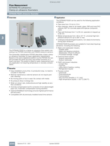
OverviewThe Flexim F601 Ultrasonic Liquid Flow Metermeasures liquid and energy flow in a pipe. It hasclamp-on sensors for non-intrusive installation andmeasurement, without requiring probes be physicallyinserted into the pipe. The F601 has data loggingcapabilities and a digital display for instantaneous flowmeasurements.421232Figure 1 Flexim F601 parts1) Control console2) Ultrasonic transducers3) Magnetic transducer mounting rails4) RTD temperature probes (PT100)Not shown:5) Power supply6) Pipe diameter tape measure7) Chain extensions8) Pipe wall thickness gaugeIn mechanical systems, ultrasonic liquid flow metersare most commonly used for HVAC chilled and hotwater applications but are also useful in industrialprocesses. All applications require that no gas-phasesubstance is present.ApplicationsThe F601 Flow Meter is often used for: liquid and/or thermal energy flow Water demand analysis, including leaks. Theportable flow meter can serve as a sub-meter tomeasure cumulative amount of water used by adevice or a sub-system of a larger meteredsystem. Diagnosing system performance issues likevariation in flow and flow directionThermal Flow MonitoringThe F601 kit includes two precision RTD temperatureprobes whose outputs are integrated with flowmeasurements at the meter. Thus it is well suited forenergy flow measurements. Thermal flow is calculatedin the meter using the flow rate and the associatedsupply and return fluid temperatures.Note: All FUM citations in this document refer to theFluxus F601 User Manual (UMFLUXUS F6V4-2ENdated 2011-03-29) unless otherwise noted.
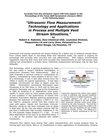
Theory of transit-time flow measurementFlow TransducersT1Direction of flowFigure 2a The ultrasonic signal takes time T1 to traveldownstream between transducersHow it Works (Figures 2a&b)The flow meter uses a pair of ultrasonic wave transducers, with eachtransducer sending and receiving coded ultrasonic signals throughthe fluid. In Transit time mode, when the fluid is flowing, signaltransit time in the downstream direction (Figure 2a) is shorter than inthe upstream direction (Figure 2b). The flow meter measures thistime difference (ΔT), which is proportional to the flow velocity. Itthen calculates velocity based on ΔT and other conditions providedby the user including liquid temperature, pipe characteristics, andfluid characteristics. See Fluxus F601 User Manual (FUM) chapter 3page 15 for more information on theory of operation.T2Direction of flowFigure 2b The ultrasonic signal takes time T2 to travelupstream between transducersIf particulates or entrained bubbles prevent good transit timemeasurements, the meter can be configured to use Flexim’s Dopplertechnology (called NoiseTrek mode) instead of transit time. See FUM“3.2.2 Determination of the Volumetric Flow Rate in the NoiseTrekMode” on pages 17 – 18 for theory of operation.HybridTrek is the same as NoiseTrek, but it automatically switchesbetween Transit time and Doppler. It is set in the SYSTEMsettings\Measuring branch of the menu system. See FUM “13.3Settings of the HybridTrek Mode” on p.83-4 for details.Figure 3a Locate sensors following the 2/3 – 1/3 rule witha minimum distance of 15x pipe diameters between flowobstructions (pipe fittings, probes, etc.)OperationInstallation and Setup1. If you plan to integrate the Flexim flow data with data fromother sources taken at the same time, you should synchronize alldata to a common clock. See Appendix C, Downloading data, formore information before proceeding further.2. Select pipe monitoring point for transducer mounting (FUM ch5p23). See figure 3a.Figure3b Pipe mounting using magnetic attachments3. Prepare the pipe surface at the monitoring point (FUM ch8.1p51). Observe the 3 o’clock/9 o’clock orientation if mounting onhorizontal pipe runs.index4. Connect the flow transducer cable to the meter (FUM ch6.3 p30).See figure 4.Channel “A”Figure 4 Insert transducer cable end into meterchannel “A”. Observe index key and conductor pinsduring insertion.5. Mount the flow transducer set on the pipe at the selectedmonitoring point without couplant. See figure 3b. Observe thecorrect positioning of the transducers by noting the embossedflow direction arrow (see figure 7 on page 4 of this document,and FUM chs 8.2 and 8.3, p51-4).
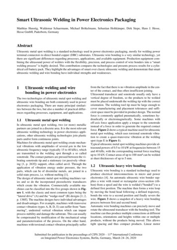
6. Review keypad operation before proceeding (FUM ch 4.4 p21). Seefigure 5.7. Turn meter on (FUM ch 10.1 p61). See figure 5. The meter willbriefly display a message saying “CLAMPON DETECTED ON A:” (or B ifchannel B is used for transducer input), followed by a brief meter IDmessage. Then the main menu appears in the meter’s digital displaywith one of 4 options selected: par (parameters), mea (measuring),opt (output options), or sf (special functions). See figure 6.Off(3x)OnFigure 5 Turn meter on and off (UM10.1 p61).MENU Navigation: #8 and #2 keys to scroll up and down #4 and #6 keys to scroll left or right Press ENTER to make a selection Clear Key (“C”) to clear/delete an entered value Break key (“BRK”) to interrupt measurementOR Jump to Main Menu at any time duringsetup or operation8. Note: If you plan to integrate flow data with data from othersources, please follow the steps in Appendix C: Synchronize F601 toPC clock from the FluxData application and skip this step.Otherwise, Using the keypad and keys, move the cursor to theSF branch and press [ENTER]. Press the or keys to select SystemSettings [ENTER], then select Set Clock [ENTER]. Select OK to acceptor NEW to update the displayed time. Press [ENTER] to acceptchanges. Repeat this process for the Date value. Then press the[BRK] key to return to the top menu.9. Unless you are logging at 5 second intervals or faster, set SFmenu\Special Function\System Settings\storing\Storage Mode Average (FUM ch 14.1.3 p95).Refer to the laminated Quick Start (QS) Guide card to continue withsetup steps 10, 11, and 12 below. Begin with the Parameter Input menubranch, then turn the card over and continue with Output Options andMeasuring branches.10. Move cursor to the PAR branch (FUM ch 11.1 pp 65-70) and enterparameter values indicated in the QS Guide at the prompts. As youproceed, note the following: Figure 6 Meter’s Main Menu display with PAR selected. Measure outside pipe diameter with the pipe diameter tapemeasure provided with the meter.If the pipe material is known, use the pipe materials data sheetto look up wall thickness based on the pipe diameter for thatmaterial. If pipe material is unknown, use the thickness gage tomeasure the pipe wall thickness (see Appendix B in thisdocument).For pipe roughness value, use the meter’s default value, or seeFUM Appendix C-2, p234 (.0005” - .002” for carbon steel).After all values are entered, press the BRK key to return to themain menu.11. Follow QS guide for OPT values (FUM ch 12.1 p76). Data logging isactivated in this branch if desired (FUM ch 14 p93). If temperaturelogging is desired, turn T1 and T2 on when prompted, and refer toAppendix A for more information.
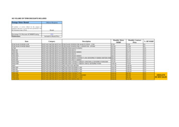
12. If logging, go to SF/System settings/storing for additional settings suchas ringbuffer, storage mode and other logging parameters (FUM ch14.1.3 p94-7). Pay particular attention to the storage mode parameter,which should usually be set to “average” when logging at intervals of 5seconds or more.Figure 7 Arrow indicates flow direction when transducersare properly placed13. Follow QS guide for MEA values (FUM ch 11.4 p70). This is the branchwhere measurements (and logging if selected) are initiated. If logging,provide a value (e. g, “1”) for Measuring Points when prompted (FUMch 11.5 p71). Select “2” or “4” for the sound paths (number oftraverses) value (FUM ch 11.5 p71). If a negative value is displayed,increase the number of traverses to the next even number (e.g., from“2” to “4”).14. Transducers should be oriented on the pipe observing the correct flowdirection indicated by the embossed arrow on top of the transducer.See figure 7.15. Transducer spacing should first be set to the value recommended bythe meter in the MEA menu. See figure 8. If the signal strength isbelow 1 bar with no coupling paste, adjust the flow transducer spacingto maximize signal strength (number of bars on the console display)and achieve a constant green LED status indicator (FUM ch 11.6 p72and QS guide). For adjusting transducer spacing for optimum accuracysee Consistency Check (FUM ch 11.6.2 p73-4). Be sure to enter anyspacing changes into the meter as explained in the manual.16. When proper spacing is achieved, remove the transducers to apply thecoupling paste then re-install the transducers. Using fingers only,tighten them snugly against the pipe but NOT “gorilla tight”. DO NOTUSE TOOLS TO TIGHTEN. Only 3-5 bars of signal strength are neededfor a reliable signal. Trying for more than 5 bars has no effect onaccuracy and has no other benefit.Figure 8 magnetic rail mounted transducers. Spacing isindicated by distance “A”, and is provided by the meter.17. If recording a running total flow is desired, set Totalizers with the “8”key after measurements have begun (FUM ch 13.2 p80). Press “8” 1time to set totalizers, or 3 times to reset them. Press “2” 3 times to turnoff totalizer.18. Measurement (flow, velocity, etc.) is in progress when the activechannel’s LED is green. However, it is NOT necessarily logging! In itsdefault configuration the meter also beeps each time data is logged tosignify that logging is in progress (SYSTEM settings\Storing\Beep onStorage on). The channel LED must be green for logging tocontinue. Please note that hitting the BRK key halts logging and realtime flow display.19. Press the “3” and “9” keys to cycle through selected measurement anddiagnostic values such as volume, flow, totalizers, temperature, soundspeed, log file fill date, measurement status values (S, Q, c, RT, F), andbattery level (FUM ch 12.3, 12.4 and 12.5, p78-9).20. Note the F601 batteries will support up to 11 hours of logging,depending on logging interval and battery condition. For longer loggingperiods, use the power supply to provide reliable operation for theduration of the logging period.
Appendix A: temperature monitoring with 100ῼ RTD probesRefer to FUM ch20 p138 for more information on thermal flowmeasurement setup.T2/T4T1/T3Connect the RTD temperature transducers to the meter (FUMch 6.3 p30). See figures 9a and 9b.Mount the probes at properly selected prepared temperaturemonitoring points (FUM ch 9.3 and 9.4, p57-58). Usetemperature conductive paste (“heat sink compound”) ifavailable for the most accurate temperature data.Figure 9a (Optional) Insert RTD sensor cable ends intometer T1 and T2 inputs. These are threadedconnections.As noted in Operation step 10 on page 3 of this document,temperature logging is activated by turning T1 and T2 on in theOPT branch (FUM ch 14 p93). Using the or and [ENTER]keys, select the desired channel (typically “A”)From the special functions (SF) menu, use the arrow keys tonavigate to Special Funct.\SYSTEM settings\Proc.Inputs. Using the or and [ENTER] keys, select LinkTemperature then configure the following parameters: Link temperature heat or chill thermal energy heat or chill transducer location return or supply thermal energy absolute or sign T-Supply Input T1 (typical) T-Return Input T2 (typical) T(3) and T(4) no measuringReturn to the Proc. inputs menu option above. Usingarrow and ENTER keys, select PT100 / PT1000 andconfigure the following parameters:Figure 9b (Optional) Properly mounted RTD sensor withinsulating pad and chain clamp Input T1 pt100 Input T2 pt100Select T-Supply T1 and T-Return T2 (be sure the RTDplacement is reflected in your selections).For more information on temperature Inputs see FUM ch21p148-153.
Appendix B: Using the Thickness GageIf the pipe wall thickness is unknown and cannot be determined bylook up charts, use the ultrasonic thickness gage provided to measureits thickness. More information on the thickness gauge can be foundin the F601 User Manual (FUM ch 19 p133).1. Plug the gage in the console’s B channel and watch for themessage identifying the device.2. Push BRK key to go to top menu if necessaryPipe thickness gage3. Go to PAR menu [ENTER]4. Select Channel B [ENTER]5. Select Pipe material [ENTER]6. Write down C-long value if desired [ENTER]7. Hit BRK, then go to MEA menu [ENTER]8. At “wall T-inch?” prompt, make measurement (e.g., .211 forsteel pipe)9. Confirm measurement and record for later use [ENTER]. Youmay wish to compare the measurement with values found inthe pipe size data sheet for comparable pipe material.Close-up of probe’s acousticpartition boundary10. At “Transfer Data?” select yes [ENTER], but note that thevalue transfers only to current B channel and must be reentered in the A channel PAR values (see below).11. Remove thickness gage probe from channel B (to avoiddamage, do NOT pull on the cable, and pull only on the LEMOstyle connector!)12. Hit BRK, then go to PAR menu [ENTER]13. Select channel A [ENTER]14. Find wall thickness parm and enter value recorded in step 9above [ENTER]15. Hit BRK, then go to MEA menu [ENTER] and beginmeasurements.Boundary should be perpendicularto pipe axis when measuringthickness
Appendix C: Downloading dataPlease note:Historically, the Tool Lending Library has seen instability in the Fluxdata application.Recent releases appear stable, nevertheless we recommend saving files andclosing applications before downloading Flexim data as a precaution tosafeguard any work-in-progress in other applications.Synchronize F601 to PC clock from the FluxData application (optional):If you plan to integrate the Flexim flow data with data from other sources takenat the same time, you should synchronize all data to a common clock. This isbest accomplished from the FluxData application instead of the console keypad,but in either case must be done BEFORE logging is started for any data sourceyou intend to synchronize. Follow the first 3 steps below. Then, in the FluxDataapplication, select menu option DUT / Date & Time, and click “Select ActualTime”, then OK. The meter and PC clocks now agree, and data from any otherloggers also synchronized to the same PC will be easily integrated usingspreadsheet or database software.1. Install FluxData software on your PC from the software diskette provided.2. Connect meter to your PC with RS232 cable into a COM port or a USB RS232serial port adapter (e.g., Keyspan). If using a USB adapter, make a note ofthe COM port assigned to the connection.3. Start FluxData.exe4. Confirm the proper COM port from step 2 is set in the application(options/serial interface, select COM port in dropdown listbox). Click Save(BTW, “Abbrechen” is German for “Cancel”), then OK (FUP 14.2.7 p101-2)5. The Protocol button displays the connection parameters and will match themeter’s default values (9600 baud/8 bits/even parity/2 stop bits). Leavethem and block size at their default values (FUP p99 sect 14.2.4). Thesevalues must agree with the PC’s Device Manager COM port settings.6. To assure that all logged data is downloaded at the end of the logging period,stop logging with the BRK key before downloading. If you only need a datasample to verify operation, you may leave the meter logging and avoidinterrupting the log file.7. Click File/Receive to download data (or the leftmost icon in the toolbar).8. Downloading data during data logging interrupts but does not stop logging.Logging resumes after download is complete (1 or more minutes).9. Neither downloading data nor interrupting logging deletes previously loggeddata. To delete stored records set Special Funct.\Delete Meas. Values\ReallyDelete yes (FUP p97 sect 14.1.5).10. By default, totalizers do not reset between logging sessions. Set SpecialFunct.\SYSTEM settings\Measuring\Quantity recall OFF to reset totalizers onany interruption. During logging the totalizers can be reset by pressing Cthree times (FUP p131 sect 18.8).
Other interesting and helpful information See HotCodes handout for more information on HotCodes p63 sect10.3 For imperial/SI units selection go to sf\system settings\dialogs menus\ For more imperial/SI units selection use HotCode 007020 If setting display contrast and display goes blank, reset with HotCode555000 (system settings\miscellaneous\contrast) For programming tree see p62 sect 10.2.2 For BTU Mode p143 sect 20.3 If medium temperature varies more than /- 20 degrees, consider RTDinput p69 sect 10.3 Memory capacity: When logging only one physical quantity (e.g.,GPM) on one measuring channel, use the following table to estimatelogging duration based on logging interval and use of totalizers:1 secno totalizers 31 hrsone totalizer 13 hrs 10 sec1 min13 days 78 days5.4 days 31 daysTo review remaining memory (for log files), see p97 sect 14.1.6(sf\special functions\instrument inform.\free 112493)To reset the meter to factory inputs, restart the meter and enterHotCode 909000 at the home screen immediately after turning on themeter. Follow the prompts. Next, simultaneously press the ENTER,BRK and C keys, releasing first the ENTER key, then the BRK key onesecond later, then finally the C key. Follow the prompts.If signal strength is good at zero flow but diminishes when flow is present, itmay be a sign of entrained air bubbles preventing a good signal. Considerconfiguring the meter for direct (one traverse) measurement.
The flow meter uses a pair of ultrasonic wave transducers, with each . p51). horizontal pipe runs. flow direction arrow and . How it Works (Figures 2a&b) transducer sending and receiving coded ultrasonic signals through the fluid. In. Transit time mode, when the fluid is flowing, signal transit time in the downstream direction (Figure 2a) is .