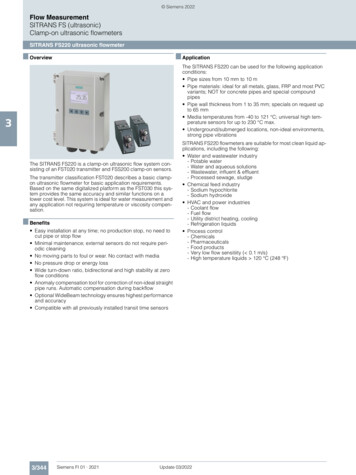
Transcription
RApplication NoteGE PanametricsUltrasonic Flow MeterPart IConfiguring the PT878 TransportUltrasonic Flow MeterOverviewThe PT878 TransPort Ultrasonic Flow Meter: Measures liquid flow in a pipe. Is a non-intrusive, clamp-on ultrasonic liquid flow meter for chilledand hot water applications Monitors flow of fluids that are homogenous, relatively clean, flowingsteadily, and have no gas-phase substance present Has data logging capabilities and a digital display for instantaneousflow measurementsApplicationsFigure 1: Flow meter installed inthe field.The PT878 Flow Meter is often used for: Water demand analysis, including leaks. The portable flow meter canserve as a sub-meter to measure cumulative amount of water used bya device or a sub-system of a larger metered system. Diagnosing system performance issues like variation in flow and flowdirection Assessing load variation in hydronic heating or cooling systems.Load is calculated using the flow rate and the associated supply andreturn fluid temperatures. This application is beyond the scope of thisApplication Note.How it WorksThis ultrasonic flow meter uses a pair of transducers, with each transducersending and receiving coded ultrasonic signals through the fluid. When thefluid is flowing, signal transit time in the downstream direction (Figure 2a) isshorter than in the upstream direction (Figure 2b). The difference betweenthese transit times is proportional to the flow velocity. The flow metermeasures this time difference and uses programmed pipe parameters todetermine flow rate and direction.Page 1 of 15
Flow TransducersBADirectionof Flowt1Directionof Flowt2Figure 2: Theory of transit-time flow measurementA) Top view of pipe. The ultrasonic signal takes time t1 to travel downstream betweentransducers.B) The ultrasonic signal takes time t2 to travel upstream between transducers.*The flow meter uses the difference between the transit times (t2 - t1 Δt), along with theparameters input by the user, to calculate fluid speed and volume flow. If the transit timeis negative, the flow is moving opposite the expected direction.This Application NoteThis Application Note consists of two parts. Part I describes how toconfigure the meter for flow measurements and data logging using thekeypad interface. Part II describes how to install two different types ofultrasonic flow transducers: those designed for pipes of between two andtwenty-four inches in diameter and those designed for pipes of less than twoinches in diameter.Components of the Ultrasonic Flow Meter KitFigure 3: The flow meter kit.1.2.3.4.5.6.TransPort portable flow meterMeasurement rails, including one indexed rail and one un-indexed rail.Clamping fixtures and chainsTransducer cablesUltrasonic transducersSmall pipe ultrasonic transducers (may be included instead of standardtransducers)7. AC power adapter (not shown)8. Ultrasonic couplant (not shown)9. Pipe diameter tape (not shown)10. Thickness gauge (not shown)Powering Up and Shutting Down the Meter1. Press the red button to power up the meter.2. To shut down the meter, press the red power button until the shutdownoptions screen appears. Choose Shutdown to shut to meter off, Sleep toput the meter in idle mode, or Cancel to resume operation.Page 2 of 15
Using Battery PowerA new fully charged battery can provide a maximum of 8 to 10 hours ofcontinuous operation. Batteries must be charged 8 hours to receive themaximum charge. The batteries recharge when the unit is plugged in to ACpower. When data logging, it is recommended that the PT878 be run on theAC power.When the meter is running on battery power, the battery icon in the upperright-hand corner of the screen will show a battery level. When the meteris running on AC power, the battery icon will either indicate that the batteryis charging or will contain a lightning-bolt symbol when the battery is fullycharged.Defining a SiteBefore entering new meter configuration parameters the user must createa new site. Previously saved parameters can be reused by selecting anexisting site and using it directly or using it as a template for a new site.Creating a New Site1. Press the Menu button until the menu list appears at the top of thescreen.2. Use the arrow keys to select the Site menu and press Enter. SiteManager will be highlighted by default (Figure 4).Figure 4: Screen after pressing the Menu buttonand selecting the Site menu.3. Press Enter to open the Site Manager menu.4. Press the Menu button to highlight the File menu (Figure 5) and pressEnter. New will be highlighted by default.Page 3 of 15
Figure 5: Site Manager screen with the File menu open5. Press Enter to open the New Site screen.6. Press F1 (Delete) to delete the default site name and use the arrow keysto navigate the alphanumeric table to enter a descriptive site name ofup to 8 characters. Press Enter to select each character. Press F3 (OK)when the complete site name has been entered.7. Choose whether or not to use the selected site as a template. (Allparameters are editable so this selection is not critical, but may savetime if there is an existing site with similar characteristics alreadyprogrammed into the meter.)8. Press F3 (Exit) to exit the Site Manager.Selecting an Existing Site1. Press the Menu button until the menu list appears at the top of thescreen.2. Use the arrow keys to select the Site menu and press Enter. SiteManager will be highlighted by default (Figure 4).3. Press Enter to open the Site Manager menu (Figure 6).4. Use the up/down arrow keys to highlight the site the user wishes toselect.Figure 6: Site Manager screen with list of existingsites displayedPage 4 of 15
5. Press the Menu button to highlight the File menu and press Enter(Figure 5).6. Use the up/down arrow keys to highlight Open and press Enter.7. Press F3 (Yes) or Enter to select the desired site.8. Press F3 (Exit) to exit the Site Manager.Configuring Flow ParametersThe five main configuration tabs are Transducer, Pipe, Lining, Fluid andPath. The information entered is used by the meter to calculate the fluidflow rate.Many configuration parameters can be, and if possible should be, set upbefore going into the field. Table 1 lists parameters that can be configuredwithout field measurements. Table 2 lists parameters that must bemeasured in the field. Each parameter is identified by its corresponding tab,field name, and parameter description. Calculated fields are not includedon either table.TabFieldParameterNotesTransducer TypeTransducer type Always clamp-on.Transducer Transducer Transducer model Most commonly used#transducers:#24 - 1/2” to 2” pipe.#402 - 2” to 24” pipe.#407 - 1/2” to 6” undSpeedTempFluidGlycolPathTraversesFluidFluidPipe materialActivate Tracking Usually OFF. Used forWindowstroubleshooting.Fluid typeSound SpeedEditable only if Other is theselected fluid.Fluid temperature Editable unless Water/Glycolis the selected fluid.Percent glycolEditable only if Water/Glycol isthe selected fluid.# of signalNumber of times thetraversesultrasonic signal crosses thepipe.Table 1: PT878 configuration parameters that do not require field measurementsPage 5 of 15
TabFieldParameterTransducer Wedge Tmp ApproximatetransducertemperaturePipeOD, inPipeWall, inPipe outsidediameterPipe wallthicknessNotesUse pipe surface temperature.Measure with surfacetemperature probe or IRthermometer.Measure with pipe diametertape.Measure with PT878 thicknessgauge.Table 2: PT878 configuration parameters that require field measurementsTransducer Tab1. Press F1 (Transducer) to display the Transducer configuration tab(Figure 7).Table 7: Transducer configuration tab2. Use the down arrow key to select the transducer Type. If Clamp-on isnot selected, use horizontal arrow key to highlight Clamp-on. PressEnter to accept the entry.3. Use the down arrow to highlight the Transducer field. Press Enter toview the list of transducers. See Table 1 for a list of transducer types.4. Use up/down arrow keys to highlight correct transducer #. Press Enteraccept the entry. Transducers are chosen based on pipe diameter andfluid temperature.5. The next field is labeled Wedge Tmp. The wedge temperature is theapproximate temperature of the ultrasonic transducer (“wedge”)which can be assumed to equal the pipe surface temperature. Thistemperature can be measured with a surface temperature meter or anIR thermometer. If using an IR thermometer, to avoid low readings dueto low emissivity of shiny metallic pipe, apply opaque tape to the locationon the pipe where the temperature will be read.6. Use the down arrow to highlight the Wedge Tmp field. Press Enter toclear field and use the numeric keys to enter the wedge temperature.Press Enter to accept the value.7. Press F3 (OK) to accept the changes to the Transducer tab configurationparameters and return to the main display screen.Page 6 of 15
Pipe Tab8. Press F1 (Transducer) to display the meter configuration tabs. Use theright arrow key to select Pipe. Press Enter to open the tab (Figure 8).Figure 8: Pipe configuration tab.9. Press the down arrow key to highlight pipe Material field and pressEnter to open the Material menu. Highlight the correct pipe materialfrom the list with the up/down arrow keys. Press Enter to select the pipematerial.BPipe Thickness MeasurementAC10. The GE Panametrics flow meter includes a gauge to measure pipethickness (Figure 9).11. Use the down arrow to highlight Measure Wall with TGauge box andpress Enter. The Thickness Gauge Measure screen with appear (Figure10).DFigure 9:(A) Pipe thickness gage(B) Calibration case(C) Couplant gel(D) Pipe diameter tapeFigure10: Wall Thickness measurement screen.Page 7 of 15
12. Check the calibration of the thickness gauge using the 0.2 inch and 1.5inch dual calibration block.a. Connect the thickness gauge to the keyed connector jacks on top ofthe meter.b. On the Thickness Gauge Measure screen, use the right arrow key toselect the Material tab and press Enter to open the tab.c. Use the down arrow key to highlight the Material field and pressEnter to open the Material menu. Use the arrow keys toselect Steel (Stainless 302) and press Enter to accept the selection.d. Use the arrow keys to select the Display tab and press Enter to openthe tab.e. Place a small bead of thickness gauge couplant (Couplant B) onthe 0.2 inch side of the dual calibration block and pressthe calibration gauge against that side of the block. A clock icon willappear for several seconds until the thicknessreading appears. Note the reading.f. Repeat step e with the 1.5 inch side of the calibration block.g. If the readings vary more than 0.002 inch from 0.2 inches or 0.02inch from 1.5 inches, respectively, calibrate the thickness gauge perstep 13 below. Otherwise skip calibration.13. If necessary, calibrate the thickness gauge using the 0.2 inch and 1.5inch dual calibration block.a. If it has not been done already, connect the thickness gauge to themeter and select Steel (Stainless 302) in Material field on theMaterial tab, as described in step 12a, b and c above.b. Use the arrow keys to the select the Zero tab and press Enter toopen.c. Use the arrow keys to highlight Dual Calibration and press Enter toselect.d. Use the down arrow key to highlight the Block 1 Length field. PressEnter to edit the field, enter 0.2 and press Enter again.e. Use the right arrow key to highlight the box containing the word“Calibrate” located to the right of the Block 1 Length field. PressEnter. The box will now read “Ready”.f. Place a small bead of thickness gauge couplant (Couplant B) onthe 0.2 inch side of the dual calibration block and press thecalibration gauge against that side of the block. Press Enter.A clock icon will appear for several seconds and then the boxwill again read “Calibrate”.g. Repeat steps f, g and h for the 1.5 inch side of the dual calibrationblock using the fields associated with Block 2 Length. TheSet button will appear once the user is done calibrating with the 1.5side of the dual calibration block.h. Once the Set button appears, press Enter. Press F3 to go back tothe Pipe tab.i. Check that calibration has been successful. With Measure Wallwith TGauge highlighted, press Enter to return to the ThicknessGauge Measure screen. Evaluate the results as indicated inPage 8 of 1512g above.
14. Before measuring pipe thickness, select the correct pipe material. Fromthe Thickness Gauge Measure screen, use the right arrow key to selectthe Material tab and press Enter. Use the down arrow key to highlightthe Material field and press Enter to open the Material menu. Use thearrow keys to select the appropriate pipe material and press Enter toaccept the selection.15. Prepare the pipe. The user will take thickness measurements on thesection of pipe where the clamping fixture, rails and transducers will beinstalled. On this section of pipe, cut back the insulation, remove anypaint, and clean the pipe and sand off any corrosion or rough spots. Ifthe pipe is extremely rough the thickness measurements may not beaccurate and, once the transducers are installed, the ultrasonic signalwill be scattered by the rough surface and will not be received by theflow meter, preventing flow measurement.16. Apply thickness gauge couplant (Couplant B) at the spot on the pipewhere the user will be making the thickness measurement. Thesmoother the pipe surface the thinner the couplant should be applied.The line on the face of the transducer should be positioned so that it isperpendicular to the liquid flow in the pipe (Figure 11).Figure 11: Proper alignment ofthickness transducer on cylindricalrun of pipe.Figure 12: Pipe-diameter tapebeing used to measure a 3.5 in.diameter pipe.17. Hold the pipe thickness transducer flat against the pipe surface. Notethe measured pipe wall thickness value displayed on the meter. PressF3 (OK) to return to the Pipe menu. Use the arrow keys to highlight theWall, in field. Press Enter to clear the field and enter the pipe thicknesswith the numeric keys. Press Enter to accept the value.18. Measure the outside diameter of the pipe with the pipe diametermeasuring tape included with the pipe thickness gauge kit, as shownin Figure 12. Use the arrow keys to toggle to the OD, in field and pressEnter to clear the field. Enter the pipe outside diameter in inches withthe numeric keys and press Enter to accept the value.19. Press F3 (OK) to accept the changes to the Pipe tab configurationparameters and return to the main display screen.Lining Tab20. Press F1 (Transducer) to display the meter configuration tabs. Use thearrow keys to select the Lining tab and press Enter.21. If the pipe has no anti-corrosion lining, check that the lining Materialfield is set to None, the default value.Page 9 of 15
22. If the pipe has an anti-corrosion lining, use the arrow keys to highlightthe Material field and press Enter to open the lining Material menu.Use the up/down arrow keys to highlight the lining material. Press Enterto select.23. Press F3 (OK) to accept the default setting or the changes to the Liningtab.Fluid TabThe options available on the Fluid tab will vary depending on whether themeter’s Energy Options are enabled or disabled.Selecting Energy OptionsThis section will address Energy Options as they relate to configuration ofthe Fluid tab. Though it is beyond the scope of this Application Note, theEnergy Options screen can also be used to configure temperature inputsrequired for the meter to calculate heating or cooling loads. See the PT878Operation & Installation Guide for details.If Energy Options are disabled, the Fluid field on the Fluid tab will displaya pre-defined list of fluids, including Water, and an Other fluid option. IfEnergy Options are enabled, the Fluid field will display a list includingOther, Water, and Water/Glycol, with no additional pre-defined fluidsavailable.As a result, if the working fluid is water or a custom fluid not defined inthe PT878’s fluid list, Energy Options may be either enabled or disabled. Ifthe working fluid is a water-and-glycol mix, enabling Energy Options willsimplify the configuration of fluid parameters because the fluid will not haveto be entered as a custom fluid. In order to select a fluid other than waterfrom the PT878’s pre-defined fluid list, Energy Options must be disabled.a. To configure Energy Options, first press the Menu button until the menulist appears at the top of the screen.b. Use the arrow keys to select the Program menu and press Enter. Usethe down arrow key to select Energy (Figure 13). Press Enter again toopen the Energy Options screen (Figure 14).Figure 13: Select Energy from the Programmenu to open the Energy Options screen.Page 10 of 15
Figure 14: Energy Options screen.c. Use the arrow keys to select Enable or Disable. Press Enter and thenF3 (OK) to accept the selection and return to the main screen. Note thatwhen Energy Options are enabled a flame icon appears in the SystemTray near the bottom of the screen.24. Once the appropriate Energy Options are selected, press F1(Transducer) to display the meter configuration tabs. Use the arrow keysto highlight the Fluid tab. Press Enter to open the tab (Figure 15).Figure 15: Fluid configuration tab.25. Leave the Tracking Windows option set to “No”. Tracking windows areused for advanced trouble shooting and are beyond the scope of thisApplication Note.26. Use the arrow keys to highlight the Fluid field and press Enter to openflow meter’s Fluid list. Select either a pre-defined fluid from the Fluidlist, or, if the fluid is not on the list, select Other. Press Enter to acceptthe selection.Page 11 of 15
27. If Other was selected as the fluid type the user will need to define thefluid’s behavior by entering a sound speed into the Sound Speed field.Fluid sound speeds can be found in the Installation Reference manualtitled Sound Speed and Pipe Size Data (included with this flow meter) orin an alternative reference source. Use the arrow keys to toggle to theSound Speed field. Press Enter to clear the field and enter the speedof sound for the appropriate fluid with the numeric keys. Press Enter toaccept the selection.28. If a pre-defined fluid or Other has been chosen from the Fluid list, usethe arrow keys to highlight the fluid Temperature field.29. If a water/glycol mix has been selected as the working fluid, the Glycolfield will be editable rather than the fluid Temperature field. Use thearrow keys to highlight the Glycol percent field.30. Once the editable field has been selected (either Temperature orGlycol), press Enter to clear the field and use the numeric keys to enterappropriate value. Press Enter to accept the new value.31. Press F3 (OK) to accept the changes to the Fluid tab configurationparameters and return to the main display screen.Path Tab32. Press F1 (Transducer) to display the meter configuration tabs. Use thearrow keys to highlight the Path tab and press Enter (Figure 16). TheTraverses field is the only editable field on the Path tab. The transducerspacing shown in the Spacing field is calculated based on all of the otheruser-input parameters and is required for correct installation of the flowtransducers.Figure 16: Path configuration tab.33. The value in the Traverses field indicates the number of times theultrasonic signal crosses through the fluid from one side of the pipeto the other in transit between the two ultrasonic flow transducers.See Figure17. To input this value, use the arrow keys to highlight theTraverses field. Press Enter. Use the arrow keys to choose 2 traverses,unless the user has a reason to use a different transducer configuration.Press Enter to select.Page 12 of 15
Flow TransducerUltrasonic Signal PathAB11C2D1231234Figure 17: Ultrasonic signal traversesTop views of pipe. The number of traverses indicates the number of times theultrasonic signal crosses the pipe. a) One (1) traverse. b) Two (2) traversesc) Three (3) traverses c) Four (4) traverses. It is most common to use two (2)traverses. Additional traverses weaken the signal but provide a more accurateflow measurement.34. The value in the Spacing field is the Transducer Spacing calculated bythe meter after all of the measurement parameters have been entered.Press F3 (OK). If prompted, press F3 (OK) again to acknowledge theWarning message that indicates that the transducer spacing haschanged. Make note of the Transducer Spacing value.35. Press F3 (Save Now). Press F3 (Yes) to choose the site name that isdisplayed in the Save Site screen.Changing Display Values and UnitsTo change the display units between Metric and English units do thefollowing:1. Press the Menu button until the menu list appears at the top of thescreen.2. Use the arrow keys to select the Meter menu. Press Enter.3. Use the arrow keys to highlight Units. Press Enter.4. Use the arrow keys to select Metric or English units. Press F3 (OK) toaccept the selection.To display different measured and calculated values and change displayunits in any of the PT878 output windows, do the following:1. Press the Menu button until the date and time are shown at the top ofthe screen.2. Press the down arrow key until a triangle appears on the left edge of thetitle bar in the appropriate output window. Press Enter.3. Use the arrow keys to highlight Measurement and press Enter.4. Use the up and down arrow keys to highlight the desired displayparameter.5. Press the SEL button to select the parameter and use the up and downarrow keys to highlight the desired units. Press F3 (OK) to accept theselection.Page 13 of 15
Configuring Flow Meter for Data Logging1. When logging, it is recommended that the PT878 be run on AC power.Note that a new, fully-charged battery can provide a maximum of 8 to 10hours of continuous operation.2. Press the Menu button until the menu list appears at the top of thescreen.3. Use the arrow keys to highlight Logging tab, New Log and press Enter.4. Press F1 (Delete) to delete the default log name and use the arrowkeys to select a log name, pressing Enter after each letter or numberis highlighted. Press F3 (OK) when the complete log name has beenentered. Two logging configuration tabs will be displayed: General andMeasurements.General Tab5. Use the arrow keys to toggle between the Format options and pressEnter to select. Choose Linear to program the meter to stop loggingwhen the memory is full. The Linear option is the more appropriate onefor most logging applications. Choose Circular to program the meter tocontinue to log when the memory is full by overwriting the earliest datarecords with the newest data.6. Use the arrow keys to select log Type. Choose Standard and pressEnter.7. Enter the Start and End dates and times. Toggle to the correct field tohighlight. Press Enter and then edit the values in the field with the arrowkeys. Press Enter after each field has been edited and use the arrowkeys to toggle to the next field.8. Use the arrow keys to toggle to the Logging Interval field. Press Enterto activate the text box and use the numeric keys to enter the logginginterval.Measurements Tab9. Use the arrow keys to select the Measurements tab and press Enter toopen.10. Use the arrow keys to highlight one of the variable boxes on theMeasurements table. The box will initially read “NO UNITS”. Press Enterto open the Measurements variable list.11. Use the up and down arrow keys to indicate the desired variable. Pressthe SEL button to confirm the selection. The prompt automaticallymoves to the list of unit types.12. Use the arrow keys to highlight the desired units. Press the SEL buttonto select the units and then press F3 (OK) to confirm the selection.Once selected, the measurement variable and units will appear in theMeasurements table.13. Repeat for up to 12 different parameters.14. Press F3 (Activate) to Activate the Log.15. Press F3 (Exit) to exit the log menu and return to the main flow screen.Press F3 (Save Now) to save changes.Page 14 of 15
16. Note that if a log has been created and has started logging (Running), apencil with horizontal lines on its left side will appear in the System Trayat the bottom of the screen. If a log has been created but has not startedlogging (Pending), a pencil without horizontal lines will appear in theSystem Tray. If all logging is complete or no logs have been created (nologs are Pending or Running), no pencil will appear in the System Tray.Downloading the Data Log from the meter to the PC1. Load the PanaLogViwer software from the CD included with the flowmeter. This software is compatible with Windows operating systemsonly.2. Connect the serial IR port adaptor to the PC serial port. To install theadaptor, either follow the windows “New Hardware” prompts to find andinstall the default drivers or follow the manufacturer’s instructions.Manufacturer’s instructions may be provided with this meter or can be atthe manufacturer’s web site.3. If the user has difficulty connecting, make sure that the COM portselected in the IR adaptor software (e.g. COM1) matches the COMport available on the user’s computer. Use the IR adaptor installationsoftware and the computer’s Hardware Device Manager to find COM portassignment information.4. Once the IR adaptor is working, place the IR port on the adaptor directlyin front of the IR port on the meter.5. On the PT878 console, press the Menu button and use the arrow keys tohighlight the Logging menu heading. Press Enter.6. Highlight Log Manager and press Enter. Use the arrow keys to highlightthe correct log to download.7. Press the Menu button to highlight the File menu heading and pressEnter. Use the arrow keys to highlight Transfer and press Enter.8. A message will be displayed on the computer screen indicating thata file is being sent through a wireless link. Click yes to accept the filetransfer. It may take several minutes for the file to transfer to the user’scomputer. The transfer is proceeding correctly unless an error messageis displayed.9. Open the PanaLogViewer software. Choose File; Open. Select the .LOGfile and click the OPEN button.10. Click the EXPORT button to convert the .LOG file to a .CSV file that canbe opened and viewed in EXCEL. (Note that exporting directly to anXLS spreadsheet data format is unreliable and may cause the Panalogapplication to terminate without warning. However, this does notdamage the data file.)11. When finished, turn the meter power off.12. If after transferring data the user has trouble using the COM ports onhis or her computer, check the computer’s Hardware Device Manager tomake sure the IR adaptor is not monopolizing the active COM port.Page 15 of 15“PG&E” refers to Pacific Gas and Electric Company, a subsidiary of PG&E Corporation. 2010 Pacific Gas and Electric Company. All rights reserved.These offerings are funded by California utility customers and administered by PG&E under the auspices of the California Public Utilities Commission.
The PT878 TransPort Ultrasonic Flow Meter: Measures liquid flow in a pipe. Is a non-intrusive, clamp-on ultrasonic liquid flow meter for chilled . 10.The GE Panametrics flow meter includes a gauge to measure pipe thickness (Figure 9). 11.Use the down arrow to highlight Measure Wall with TGauge box and