Transcription
Excerpts from this ultrasonic report (UR-234) appear in theProceedings of the Texas A&M Symposium (January 2002)in the following paper:”Ultrasonic Flow Measurement:Technology and Applicationsin Process and Multiple VentStream Situations,”byRobert A. Rabalais, Dow Chemical USA, Louisiana Division,Plaquemine LA and Larry Sims, Panametrics Inc.Baton Rouge, LA/Houston, TXInstrument and process personnel are always looking for a better way to measure process flows.From simple steam flows to two-phase flows with entrained solids, the search is ongoing fortechnology that provides both accuracy and cost effectiveness. With today’s environmentalregulations requiring both more and more accurate flow measurements as well high-energy costsmaking fuel consumption a primary focus, traditional measurement techniques may be less thanadequate.One technology, which is gaining acceptance to meetthe new needs in today’s industrial marketplace, istransit-time ultrasonic flow measurement. (Box atright illustrates a common clamp-on configuration forliquids.) Considered by many skeptics to be too “new”of a technology, it has in fact been around since the1950s or earlier for special applications. It has beenavailable commercially (at least in Japan) since the1960s.Panametrics commercial flowmeters wereintroduced at an ISA Show in 1979 and its flare gasultrasonic flowmeter was introduced at this Symposiumin 1984 by Smalling et al. Applications have grownrapidly in recent years as more people became awareof and confident in the performance of transit timeultrasonic flowmeters. Besides spanning temperaturesbetween the extremes of cryogenic (-200 C) to veryhot (500 C), ultrasonic transit time flow meters areused with gases, liquids and two-phase mixtures.Recently, clamp-on has been extended even to gasesin steel pipe. So far, this last aspect requires that thegas have a sufficiently high acoustic impedance Z. Forair, this typically means pressure P 4 bar. In ventstack applications of the type to be described below, P 1 bar so the solution was obtained with wettedtransducers.Transit-time ultrasonic flow meters, when appliedto fluids of sufficiently high acoustic impedanceZ, use two clamp-on or wetted transducers. Oneis installed upstream and one is installeddownstream with respect to the flow direction.Each transducer transmits coded sound pulsesreceived by the other transducer. The fluid flowincreases the ultrasonic signal time of flight in thedirection of flow and decreases the time of flightagainst the direction of flow. The difference intransit-times is directly proportional to the flowvelocity.Ultrasonic flow meters have among their useful characteristics, zero excess pressure drop, nomoving parts and hence, little or no maintenance in many applications, bi-directionality, linearityUR-2341Revised 1/18/02
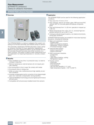
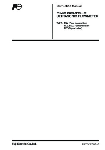
and large turndown ratios, 10:1. These characteristics are making ultrasonic flowmeters hard toignore in light of the issues facing process and design engineers today. Unfortunately, textbooksoften concentrate on the older technologies, e.g. orifice plates, venturis, so one might be led toconclude that ultrasound isn’t proven yet; that it is hard to understand; why take a chance withsomething “new”?Let’s take a look at the characteristics of ultrasonic flow measurement and how these have provenbeneficial in specific cases.Turndown. Many engineers assume that turndown is not a necessary quality of a flow meter forroutine plant flows. This is because many plants operate at relatively stable flow rates ( 5% mostof the time) once they are up and running. Why is it acceptable to be in the dark on process flowmeasurement during startup and shutdown of operating units? These are the most critical periodsof process operation in regard to safety and environmental performance as well as production andproduct quality. Ultrasonic flow meters provide the highest turndown capability of all technologiesused in modern instruments (see Fig. 1). This meter characteristic alone could lead to streamlinedoperational startups and shutdowns, which could minimize many kinds of lPressureVortex Shedding Liquid Ultrasonic Steam Ultrasonic Gas UltrasonicFig. 1. Turndown Ratio of Some Common Flowmeter Types, IncludingTransit Time Ultrasonic FlowmetersOn a new plant, meters often need to be replaced after startup due to errors in design versusactual process operation. With the high turndown and, if required, virtual immunity to viscosityvariations that ultrasonic multi-path flow meters possess, the only issue would be modifying themeter program after startup to obtain desired operating range. A tenfold change in viscosityintroduces only a 1% change in the meter factor K of a diameter path (e.g. clamp-on) ultrasonicflowmeter, for turbulent fluids.The main reason behind the large turndown is the linear response of a transit time flowmeter, incontrast to square law devices. Ability to measure laminar, transitional and turbulent flows may becontrasted with vortex shedding devices that are limited to approximately a 20:1 to 40:1 range ofturbulent flows. [See Spitzer, 2001, page 380 for details.]UR-2342Revised 1/18/02
Pressure Drop. The ability to measure flow without any excess pressure drop is anothercharacteristic of ultrasonic flow meters, and obviously quite different from P devices. Everywherein a process unit the pressure drop caused by flow measurement devices might be costing money –much of which is wasted needlessly. In many (but not all) cases, the P might be interpreted as a device. Consider cases where removal of a pressure drop such as an orifice plate could directlyresult in higher production rates. Whether you want to send more product through existing pipesor simply decrease the cost of production, ultrasonic flow meters often provide an economicalsolution, especially if “cost of ownership” is included in the calculation. The savings in energy alonewhen steam flow orifices were replaced with ultrasonic flow meters have already provided agenerous return on investment in many plants. The savings depends on the cost of energy, andwhether the pressure loss affects plant bottom line.Window Into the Process. Ultrasonic flow meters can yield V and c information, i.e., flowvelocity and speed of sound, respectively. Fluid soundspeed, which is a basic parameter used inthe flow calculation, provides significant information on the process stream being measured.Soundspeed can sometimes identify the fluid’s composition. This window into the composition ofthe process can transform a simple flow measurement into a useful operating and troubleshootingtool. This feature depends on the fluids being encountered, how many different compositions mightexist, temperature compensation, etc. For a well-defined liquid such as water, at temperature farfrom 74 C, the sound speed correlates well with water temperature and density. The correlationalso depends on pressure, but pressure exerts a rather small influence on sound speed.[To provide a more general solution for liquid density ρ than is available based solely on c inliquids, investigators have proposed supplementary measurements such as the attenuationcoefficient α (Babikov, 1960), or measurements of a reflection coefficient from a wetted reflectivesensor. A recent example of the latter approach is due to Van Deventer (2001). This type ofsensor yields Z, the liquid’s acoustic impedance. Density ρ is then obtained by dividing Z by c. Asfar as the present authors are aware, however, practical commercial versions of liquiddensitometers based on α or Z have not yet made it into the industrial process control field.]Some other interesting aspects of ultrasonic flow meters are:1. For clamp-on, no parts project into the pipe that can be plugged with solids and debris.2. Measurement is generally not affected by process material coating the pipe walls (as long aspipe inside diameter is not affected).3. Ability to measure bi-directional flow in a line.4. No lead lines are required as with differential pressure based flow meters (such as orificeplates or wedge meters).Maintenance costs associated with draining lead lines forcalibration or installing heat tracing to maintain temperature is eliminated.The case studies that are presented below were taken from work performed by Panametrics Inc. atthe Dow Chemical USA facility in Plaquemine, LA. They illustrate the flexibility of ultrasonic flowmeters and how they can be successfully applied in a variety of applications.Application # 1:Transfer of Flammable Liquid from a Barge to a Storage TankProblems:1. Need to monitor the product transfer rate to minimize the unloading time.2. Need to stop the transfer as soon as the barge is empty to prevent over-pressuring thestorage tank and releasing vapors to the atmosphere.UR-2343Revised 1/18/02
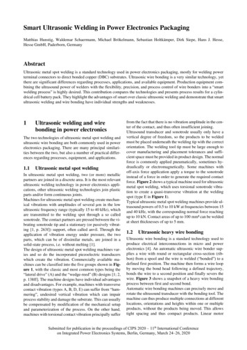
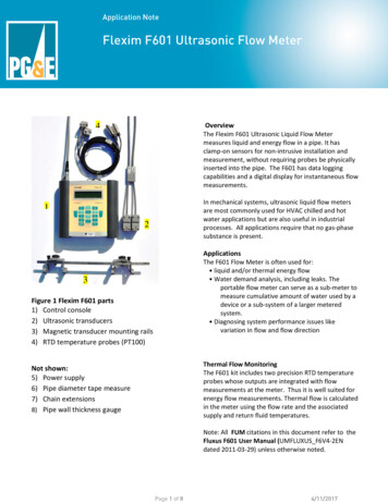
Solution:Install an ultrasonic flowmeter and monitor the product flow and soundspeed.Other solutions considered:1. Use the derivative of the level to calculate the transfer rate and monitor the storage tankpressure to detect when the barge was empty. This was not implemented because thestorage tank diameter was very large and the stability of the level indication did notmake the derivative calculation an attractive solution. Stopping the transfer by detectingthe pressure rise, when the storage tank vapor space was very small, was considered toorisky to implement.2. The use of a magnetic flow meter was considered, but could not be used since the liquidproduct was not conductive.3. Flow and level switches were considered but were quickly dismissed in favor of analogsignals.Process conditions:Pressure:Temperature:Flow:Fluid soundspeed:Line:50 psigAmbient0-500 gpm4000 ft/sec10″ carbon steelFlowmeter details:Model:Transducer Frequency:Output A:Output B:Panametrics DF8681 MHz0-500 gpm3000-5000 ft/secFig. 2. Installation of DF868 ElectronicsUR-2344Revised 1/18/02
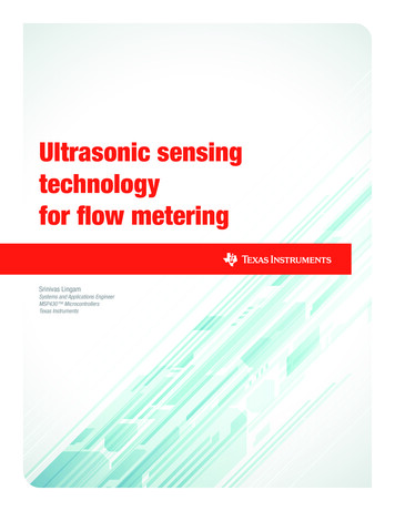
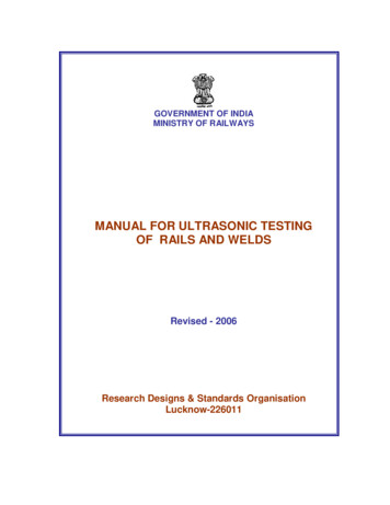
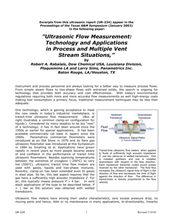
Fig. 3. Installation of Ultrasonic Transducers on 10” CS PipeTransporting Flammable Liquid from Barge to Storage TankResults:The flowmeter is functioning well. The flow indication allows a maximum transfer rate fromthe barge to the tank. The meter goes into a fault condition when the barge is emptybecause the transfer line is no longer completely full of liquid. The ultrasonic meter detectsan error in soundspeed for liquid material and goes into fault. Detection of the flowmeterfault condition automatically shuts down the transfer before the storage tank overpressures.Application # 2:Bi-directional Measurement of Air Flow at Atmospheric Pressure in Vent LineProblems:1. Determine volume of air flowing into each of 5 vessels through vent lines under normaloperating conditions and measure the flow to atmosphere through same vent lines underabnormal operating conditions.2. The air composition will vary in moisture content, temperature, and the amount ofhydrocarbon vapors depending upon direction of flow.3. Meters must function properly and accurately for control and environmental reportingpurposes.4. Redundant flow measurements required.Solution:Install an ultrasonic flowmeter spool piece on each vent line with 4 transducers. Each set oftransducers programmed for bi-directional flow.UR-2345Revised 1/18/02
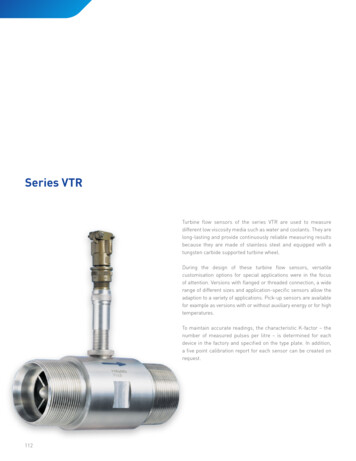
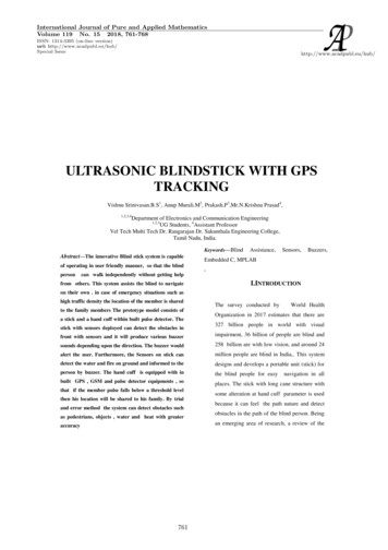
Other solutions considered:1. Averaging pitot tubes were considered but the poor turndown capability and lowdifferential pressure made this method of measurement impossible.2. Thermal flow meters were considered but dismissed due to varying stream compositionas well as polymer fines in the vent stream.Process conditions:Pressure:Temperature:Flow:Fluid soundspeed:Line:0 psigAmbient or slightly above ambient.-5000 to 5000 SCFM1150 ft/sec16″ aluminum pipeFlowmeter details:Model:Transducers:Output A:Output B:GM868100 KHz-5000 to 5000 SCFM-5000 to 5000 SCFMFig. 4. Installation of Two Consoles, Each Containing GM868ElectronicsUR-2346Revised 1/18/02
Fig. 5. Installation of Two-Path Ultrasonic Transducers on 16”Aluminum Pipe Measuring Bi-Directional FlowResults:The flow meters are functioning satisfactorily. Bi-directional flow measurement result isstable and sufficient for both process and environmental control.Application # 3:Vent Flow to Throx Unit (Thermal Heat Recovery Oxidizer – Waste Burner)Problems:1.2.3.4.5.6.Varying stream components, pressure, temperature and concentrations.Saturated corrosive vapor.Need to measure fluid velocity and volumetric flow.Very low pressure.High turndown required.Trip function at low flow required.Solution:Install an ultrasonic flowmeter flanged spool piece on vent line with 2 transducers.Other solutions considered:1. A wedge flow meter was previously installed. The meter accuracy was affected too muchby stream composition. A new flow meter solution was required. Therefore, the wedgemeter was being removed.2. A coriolis flow meter considered, but concerns over performance with so little pressuredrop available eliminated this option.Process conditions:Pressure:Temperature:UR-2340-20 psig50-125 ºF7Revised 1/18/02
Flow:Fluid soundspeed:Line:Flowmeter details:Model:Transducers:Output A:Output B:0-5250 ACFH1000 ft/sec3″ titaniumGM868100 KHz0 - 5250 ACFH750-1250 ft/secFig. 6.Installation of Ultrasonic Transducers on 3”Titanium Pipe Measuring a Vent Stream with ContinuouslyVarying Gas Composition to Throx UnitResults:The flow meter has been functioning without a problem since 1998, i.e. for 3 years at thetime of this January 2002 Symposium. It was hoped that the fluid soundspeed could beused as an indicator of the concentration of one of the two varying components in thestream, but both have similar soundspeed. With the two components having soundspeedsso similar to each other, it is impossible for the meter to differentiate them based on soundspeed alone.Concluding RemarksThese are just a few of the thousands of successful applications of transit time ultrasonic flowmeters in industry. In some articles it is implied or stated that transit time is for clean liquids andDoppler is for “dirty” liquids. This incorrect myth assumes that sound can travel across a tilteddiameter path only through clean liquids. (If that were true, how would a Doppler soundbeam everreach into the fluid far enough to scatter, and survive the return trip?) The incorrect statementsalso assume that the sound beam from a Doppler flowmeter cannot scatter from a clean liquid.Today, turbulence is sufficient to scatter ultrasound and some Doppler flowmeters can thereforework on clean liquids. Turbulence also enables tag flowmeters to work.UR-2348Revised 1/18/02
Maybe these statements about transit time for clean, Doppler for dirty, were true of the technologyavailable in the 1960s, but the statements do not apply to today’s flowmeters.Correct statements for the transit time ultrasonic flowmeter would go something like this: transittime flowmeters work in gases, liquids and some two-phase mixtures provided a reasonable signalto noise ratio is obtained. For gases there is a further caveat: the flow should not exceed aboutMach 0.1.Clamp-on applies now to gases such as air at atmospheric pressure in plastic pipe, and in steelpipe, at pressures above about 4 bar. If the gas were argon, lower pressure would suffice, while forhydrogen or helium, higher pressure is needed, at this time. The 4 bar guideline depends on pipecondition, diameter and other factors.As the technology continues to improve, these limits can be expected to change or vanish,meaning, the scope of applications will expand.Repeatability for most transit time flowmeters usually is better than 1% and can be as good as0.1%. Accuracy (or uncertainty) is a function of the profile uncertainty and other factors.Depending on the location and number of paths, accuracies can be 0.3%. This optimistic result hasbeen achieved in some recent gas calibration tests, but the reader needs to understand, in thefield, conditions at the site and the care exercised in installing the flowmeter may lead to adifferent accuracy figure. In the case of clamp-on, it is difficult and perhaps unnecessary to verifyaccuracy at the installation. An alternative is to “prove” the clamp-on at a calibration laboratory,but this usually means, on a similar but not necessarily identical section of pipe.AcknowledgmentThe authors acknowledge Panametrics’ permission to excerpt portions from its copyrighted reportsUR-226, 234, 260 and 266; and Dow’s permission to report on several applications at theirPlaquemine facility in Louisiana.UR-2349Revised 1/18/02
References for More InformationAsher, R. C., Ultrasonic Sensors for Chemical Process Plant, Institute of Physics Publishing, London(1997).Babikov, O. I., Ultrasonics and Its Industrial Applications, Consultants Bureau, Plenium Press, NewYork (1960).Miller, R. W., Flow Measurement Engineering Handbook, 3rd Ed., McGraw-Hill (1996).Liu, Y., Lynnworth, L. C., and Zimmerman, M. A., Buffer Waveguides for Flow Measurement in HotFluids, Ultrasonics, 36 (1-5), pp. 305-315 (February 1998).Lynnworth, L. C., Clamp-On Flowmeters for Fluids, Sensors, 18, (8), pp. 50-59 (Aug. 2001);Measuring Flow Under Tough Conditions Using Ultrasonics, Control Solutions, 74 (11), pp. 14-19(2001).Lynnworth, L. C., Ultrasonic Measurements for Process Control, Theory, Techniques, Applications,Academic Press (1989).Papadakis, E. P., (Guest Editor), Ultrasonic Instruments and Devices: Reference for ModernInstrumentation, Techniques, and Technology, 23, in the series Physical Acoustics, Academic Press(1999).Scelzo, M., A Clamp-on Ultrasonic Flowmeter for Gases, Flow Control, 7 (9) pp. 34-37 (Sept.2001).Smalling, J. W., Braswell, L. D., Lynnworth, L. C., and Wallace, D. R., Flare Gas Ultrasonic FlowMeter, Proceedings 39th Texas A&M Annual Symposium on Instrumentation for the ProcessIndustries, pp. 27-38 (January 17-20, 1984); Smalling, J. W., L. D. Braswell, and L. C. Lynnworth,Apparatus and Methods for Measuring Fluid Flow Parameters, U.S. Patent 4,856,321 (August 15,1989); U.S. Patent 4,596,133 (June 24, 1986); U.S. Patent 4,754,650 (July 5, 1988).Spitzer, D.W. (Editor), Flow Measurement, ISA, 2nd Edition (2001).van Deventer, J., Material Investigations and Simulation Tools Towards a Design Strategy for AnUltrasonic Densitometer, Luleå University of Technology, Luleå, Sweden (2001); Van Deventer, J.A., An Ultrasonic Density Measurement Technique, Luleå University of Technology, 35 (1999).UR-23410Revised 1/18/02
Appendix A: Some background material and additional recent applications at sites otherthan Dow, Plaquemine LAIGM868Fig. A2.The Cerberus FlowMeasurement System used for PTBcertification testing, developed byJimHillofPanametricsandAndreas Weber and Hans Kastnerof RMG.Fig.A1.Clamp-onGasFlowmeter due to Shirley Ao.Patents pending.See Scelzo(2001).UPT868Fig. A4. Paths used in flare gasflowmeters,1982-2002,afterSmalling et al. (1984, 1989).Fig. A3. Guided-mode clamp-onfor ultrapure liquids in plastictubing φ 25 mm, after Jim Hilland John Pell, U.S. patent6,065,350 (May 23, 2000).UR-23411Revised 1/18/02
Appendix B: Additional Background IllustrationsNow back to “background” Major differences between gas & liquid 2001Why not clamp-on for gases?UR-23412Revised 1/18/02
Why not clamp-on for gases?An easy clamp-on air problem, solved a few years ago by Oleg Khrakovsky.Why not clamp-on for gases?UR-23413Revised 1/18/02
Why not clamp-on for gases?An easy clamp-on air problem, solved a few years ago by Oleg Khrakovsky.CEM Continuous Emissions MonitoringFrom aPanametricsbrochureFrom aU.S.patentUR-23414Revised 1/18/02
Example of a vent stack application in 1995,hot gas, two lined tees, oblique simple holdersRef: Lynnworth, L. C., Ultrasonic Gas Flowmeters, m&c (Measurements &Control), 29 (5), pp. 92-101 (October 1995).Not part of today’s talk, but a peek at May2001 Texas clamp-on gas calibration data details @ next year’s Texas A&MSymposium, maybe. 2001UR-23415Revised 1/18/02
One port rather than two(b) nozzle,vee path,echo offoppositewall of pipe(a) Proposalusing anoblique portOne-port Panametricsflowmeters, as ofJanuary 2002, werewere consideredexperimental devices.Questions aboutcommercial availabilitywill be handled by thePCI R&D Division on acase-by-case basis,until they becomestandard PCI products.(d) port,tested inflowing air inPanametricsR&D lab(c) nozzle,first and secondreflectingsurfaces 2001One port rather than two, continued.One-port Panametrics flowmeters,as of January 2002, were consideredexperimental devices. Questionsabout commercial availability will behandled by the PCI R&D Division ona case-by-case basis, until theybecome standard PCI products. 2001UR-23416Revised 1/18/02
One port rather than two, continued. 2001Conclusions from the Plaquemine Plant’sPerspective Acceptance and utilization of transit-time flowmeters for processmeasurements are definitely on the rise. Although the present Plaquemineapplications range in pipe size from 1 inch to 60 inches, the technology is oftengiven first consideration for flow measurement in process lines that are 6" andlarger. The technology is also given high consideration for all line sizes in special ordifficult process applications such as high turndown, bi-directional flow,changing stream composition, saturated vapor, etc. One should keep in mindthat gas applications in tube sizes down to 3/8" were demonstrated over tenyears ago by the first presenter. Finally, the cem examples cited early in thetalk showed smokestack diameters from 10 to 50 ft, in which high-velocity hotgas flows were measured ultrasonically about eight years ago. Theseapplications collectively represent a diameter turndown of roughly3 12 50 1800. Taking into account lab tests on tubing diameterof 1/8" OD, and cem at the upper extreme, a case can be made for claimingwith ultrasound, a diameter turndown capability over 5000. However, theequipment would not be identical over this entire range of diameters.UR-23417Revised 1/18/02
Conclusions from the Plaquemine Plant’sPerspective, continued The reliability of transit-time flowmeters for processmeasurements is now proven to the point that the usageincludes both control points and trip functions. The long-term cost of ownership for transit-time flowmetersis proving to be another advantage of this technology. Thelow pressure drop, low energy loss, minimal predictivepreventive maintenance requirements, and high reliabilityare making the selection of transit-time flowmeters a validoption and a more frequent final flowmeter choice.Acknowledgement. Contributions to this PowerPoint presentation include Dr. Shirley Ao, Oleg Khrakovsky, Jim Hill, Saul Jacobson, Yi Liu, DeanSylvia, Daryl Belock, Lin Leeming, Larry Lynnworth and Tracey Russell. The authors acknowledge permission by Dow and Panametrics forreleasing their information, photos and copyrighted material from UR-234.End of UR-234, Website Version 21 Dec. 2001 2001UR-23418Revised 1/18/02
variations that ultrasonic multi-path flow meters possess, the only issue would be modifying the meter program after startup to obtain desired operating range. A tenfold change in viscosity introduces only a 1% change in the meter factor K of a diameter path (e.g. clamp-on) ultrasonic flowmeter, for turbulent fluids.