Transcription
Ultrasonic sensingtechnologyfor flow meteringSrinivas LingamSystems and Applications EngineerMSP430 MicrocontrollersTexas Instruments
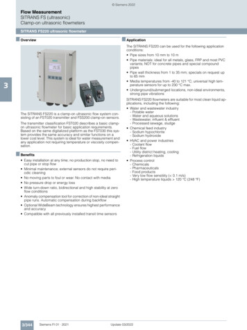
IntroductionUltrasonic sensing uses the time of flight (TOF) of an ultrasonic wave and itsdependency on the flow rate of the medium to measure and calculate volume flow,using the difference in the propagation time of the ultrasonic wave when transmittedinto and against the direction of the flow. This technology is outstanding at measuringvolume flow rates across a wide range and works with fluids like water and oil as wellas gases like air and methane.TOF-based ultrasonic meters measure flow rates based on the difference inpropagation time of ultrasonic signals in the upstream and downstream directions. Theultrasound wave travels faster when traveling in the direction of the flow and slowerwhen against the flow. This technology works whether the transducer pairs are locatedinside of a pipe or clamped to the outside of a pipe. This approach does require adirect path between the two transducers, requiring careful mechanical construction ofthe flow tube where the transducers are housed. The technology does not work in thepresence of air bubbles, which lead to significant attenuation of the ultrasound signal.Because the propagation velocity of an ultrasound wave varies between a single fluidor a composition of multiple fluids in a mixture, TOF-based ultrasonic technology canalso be used for material composition analysis.Ultrasonic flow meter configurationsIn-line flow meters can be diagonal and give thetransducers a direct line of sight, as shown inTOF-based ultrasonic flow meters have two types ofFigure 1. Or they can be reflective, where the soundconstruction: in-line or clamp-on. In-line are intrusivewave from a transmitting transducer reaches aflow meters where transducers are installed inside thesecond transducer only after reflection from a materialflow tubes and make contact with the liquid; clamp-on the surface of the pipe, as shown in Figure 2on flow meters are non-intrusive by installing theon the following page. Some industrial flow meterstransducers on the surface of the pipe and sense thewith large diameter flow tubes use two pairs ofsound wave traveling through the pipe.Figure 1. In-line and diagonal transducer placement.Ultrasonic sensing technology for flow metering2September 2017
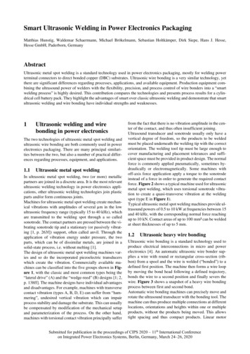
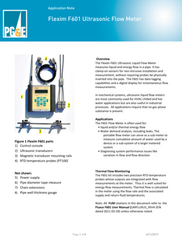
Figure 2. In-line and reflective transducer placement.transducers for improved performance,accuracy over a wide range of flow rates, from aaccommodating the larger attenuation that will occurfew liters per hour (lph) to tens of thousands nother challenge is maintaining flow-rate accuracywith2.largerpipeanddiameters,as shownin Figure3.over fluid temperatures that can range from 0 C to185 C, depending on the application. Because theT12T21velocity of an ultrasonic wave in fluid varies with thefluid’s temperature, the difference in propagation2time to take flow-rate measurements will introduceerrors when the fluid temperature changes. Forexample, the velocity of sound in water variesbetween 1,420 mps to 1,540 mps and is neitherlinear nor asymptotic in nature, as shown inFigure 5 on the following page. In general, this canlead to errors in flow-rate estimation of more than5 percent if you do not account for temperature.Figure 3. Variousof ofIn‐lineplacementof transducerpairs.Figureconfigurations3. Various configurationsIn-line placementof transducerFor improved accuracy, the system will require apairs.sensor.clamp‐on transducer placement that encounters additional signaltemperatureattenuationbecause theneeds to traversethroughtheapipematerial.It is possible, however, to construct an alternateFigure4 showsclamp-ontransducer placementthat encounters additional signal attenuation becauseapproach that takes measurements independentthe ultrasonic wave needs to traverse through theof temperature. This method entails obtaining thepipe material.volume flow rate of a fluid using the absolute time ofOne of the key challenges associatedupstream and downstream propagation or TOF, inwith ultrasonic flow meters is maintainingSensoraddition to the difference of the propagation.SensorFigure 4. Clamp‐on transducer placement.hallenges associated withFigureultrasonicflow meters is maintaining accuracy over a wide range4. Clamp-on transducer placement.m a few liters per hour (lph) to tens of thousands lph. Another challenge is maintainingcy over fluid temperatures that can range from 0 C to 85 C, depending on the application.ocity of an ultrasonic wave in fluid varies with the fluid’s temperature, the difference inUltrasonicsensing technology forflowintroducemetering3 fluid temperaturee to take flow‐ratemeasurementswillerrors when themple, the velocity of sound in water varies between 1,420mps to 1,540mps and is neitherptotic in nature, as shown in Figure 5. In general, this can lead to errors in flow‐rateSeptember 2017
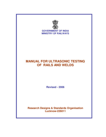
The ADC-based approach has these inherentadvantages over the TDC approach: Performance. The correlation also provideslow-pass filtering to suppress noise. Thisis implemented efficiently on the lowenergy accelerator in the Texas InstrumentsMSP430FR6047 MCU. The correlationapproach results in a benefit of 3–4 noiselower standard deviation. The correlation filteralso suppresses interference like line noise. Robustness to signal-amplitude variations.Figure 5. The velocity of ultrasound in water as a function of watertemperature.The algorithm based on the correlationAnalog-to-digital converter (ADC)based processing advantagesamplitude, transducer-to-transducer variationtechnique, is insensitive to the received signaland temperature variation. Signal amplitudevariation is observed frequently in high flowSeveral different approaches can be used to obtainrates. Robustness is a significant advantagethe difference in the upstream and downstreamTOF. One approach uses the zero crossing of awhen transducer performance degrades overtime-to-digital converted (TDC) signal. Anothertime, since some applications deploy flowcorrelates the signal obtained after analog-to-meters for more than 10 years. ADC-based processing obtains the signaldigital conversion (ADC) to the signal received atthe transducer.envelope naturally. The availability of theThe TDC technique uses an initial threshold crossingsignal amplitude information enables tuning tofor the signal followed by zero crossings of thethe transducer frequencies. Also, you can usesignal, as shown in Figure 6.slow variations in the envelope across timeto detect transducer aging. The ADC-basedIn the correlation-based ADC technique, the wholeapproach is also amenable to automatic gainwaveform is captured and stored for the signalcontrol (AGC), which can boost the receivedreceived at the transducer for both the upstreamsignal if the transducer gain reduces over timeand downstream measurements. Performing(again, due to aging). As the correlation-basedpost-processing on the waveform determines thealgorithm receives the amplified signal thatdifferential TOF.maintains the output signal level,STOP enableSTOP 1, 2, 3, 4even with transducer aging, thesystem performance does notdegrade over time.Figure 7 on the following page isa functional block diagram of thecorrelation-based ADC approach,Figure 6. Zero-crossing-based TDC technique.Ultrasonic sensing technology for flow metering4September 2017
or/peak fitFigure 7. Correlation-based differential TOF estimator.which requires the use of an ADC that oversamplesThe absolute TOF will be a constant offset from thisthe received signal.threshold crossing of the envelope, as illustrated inFigure 8.Absolute TOF measurementneed for a temperature sensor and the need toMSP430FR6047 MCU ultrasonicsensing modulecompute the velocity of sound in water. There areThe functional blocks that help achieve highseveral approaches to calculating absolute TOFperformance for an ultrasonic flow meter applicationaccurately. One approach computes the envelopeare part of an analog front end (AFE) called theof the received signal and the envelope crossingultrasonic-sensing solution (USS) IP block, whichat a specified ratio to the maximum of the signal.operates independently of the MSP430 MCU’sAn absolute TOF measurement eliminates thecentral processing unit (CPU). Figure 9 on thefollowing page shows a conceptual block diagram.The ultrasonic-sensing module includes a universalLevel crossingof signal forTOF estimationUSS power supply (UUPS), a power sequencer(PSQ), a programmable pulse generator (PPG), aphysical driver and impedance matching networkToffset(PHY), a programmable gain amplifier (PGA), ahigh-speed phase-locked loop (HSPLL), a sigmadelta high-speed (SDHS) ADC, and an acquisitionADC samplingstartssequencer (ASQ).ZoomThe ultrasonic-sensing module has its ownpower domain and can be powered ON andOFF independent of the other blocks on theMSP430FR6047 MCU. You can also reset it withoutaffecting any of the other modules on the device.ToffsetThe impedance matching in the ultrasonic-sensingmodule is critical to obtain a very low drift in thedelta time-of-flight measurement over time and anyvariation in water temperature. This also leads to theability to detect very low flow rates.Figure 8. ADC captured waveform and envelope for absolute TOFcalculation, with a zoomed-in version of the initial waveform cycles inthe bottom panel.Ultrasonic sensing technology for flow metering5September 2017
Figure 9. Ultrasonic-sensing solution functional block diagram.ConclusionTI’s latest ADC-based ultrasonic sensing technologyenables smart water flow meters to deliver highprecision and accuracy. This performance can beachieved while maintaining low current consumptionthrough the integration of the ultrasonic-sensingmodule and low-energy accelerator in theMSP430FR6047 MCU.Important Notice: The products and services of Texas Instruments Incorporated and its subsidiaries described herein are sold subject to TI’s standardterms and conditions of sale. Customers are advised to obtain the most current and complete information about TI products and services before placingorders. TI assumes no l iability for applications assistance, customer’s applications or product designs, software performance, or infringement of patents.The publication of information regarding any other company’s products or services does not constitute TI’s approval, warranty or endorsement thereof.The platform bar and MSP430 are trademarks of Texas Instruments. All other trademarks are the property of their respective owners. 2017 Texas Instruments IncorporatedSWAY007
IMPORTANT NOTICE AND DISCLAIMERTI PROVIDES TECHNICAL AND RELIABILITY DATA (INCLUDING DATASHEETS), DESIGN RESOURCES (INCLUDING REFERENCEDESIGNS), APPLICATION OR OTHER DESIGN ADVICE, WEB TOOLS, SAFETY INFORMATION, AND OTHER RESOURCES “AS IS”AND WITH ALL FAULTS, AND DISCLAIMS ALL WARRANTIES, EXPRESS AND IMPLIED, INCLUDING WITHOUT LIMITATION ANYIMPLIED WARRANTIES OF MERCHANTABILITY, FITNESS FOR A PARTICULAR PURPOSE OR NON-INFRINGEMENT OF THIRDPARTY INTELLECTUAL PROPERTY RIGHTS.These resources are intended for skilled developers designing with TI products. You are solely responsible for (1) selecting the appropriateTI products for your application, (2) designing, validating and testing your application, and (3) ensuring your application meets applicablestandards, and any other safety, security, or other requirements. These resources are subject to change without notice. TI grants youpermission to use these resources only for development of an application that uses the TI products described in the resource. Otherreproduction and display of these resources is prohibited. No license is granted to any other TI intellectual property right or to any thirdparty intellectual property right. TI disclaims responsibility for, and you will fully indemnify TI and its representatives against, any claims,damages, costs, losses, and liabilities arising out of your use of these resources.TI’s products are provided subject to TI’s Terms of Sale (www.ti.com/legal/termsofsale.html) or other applicable terms available either onti.com or provided in conjunction with such TI products. TI’s provision of these resources does not expand or otherwise alter TI’s applicablewarranties or warranty disclaimers for TI products.Mailing Address: Texas Instruments, Post Office Box 655303, Dallas, Texas 75265Copyright 2019, Texas Instruments Incorporated
performance for an ultrasonic flow meter application are part of an analog front end (AFE) called the ultrasonic-sensing solution (USS) IP block, which operates independently of the MSP430 MCU's central processing unit (CPU). Figure 9 on the following page shows a conceptual block diagram. The ultrasonic-sensing module includes a universal